Direct current and its sources
With direct current, the magnitude and direction do not change over time. On modern devices it is designated by the letters DC - an abbreviation for the English Direct Current (literally translated - direct current). Its graphic designation:
Sources of direct current are batteries and accumulators. All semiconductor electronic devices work on it: mobile phones, computers, televisions, satellite systems. To power these devices from AC power, they include power supplies. They lower the network voltage to the required value and convert alternating current into direct current. Battery chargers are also AC powered and perform the same functions as power supplies.
Inverter or converter - what's the difference?
When we talk about converting electrical energy from one type to another, and talk about technical devices that implement the conversion process, we inevitably come across two concepts such as “inverter” and “converter”.
Sometimes confusion may arise: what and in what context would be correct to call an inverter and what a converter, because both devices are electrical converters and are often very similar in appearance. However, we usually don't say "converter" because we prefer to use more precise language.
So, let's figure out what an inverter is, what a converter is, and how they differ from each other.
The word “inverter” comes from the Latin “inverto”, meaning “to turn over”. In relation to electrical converters, an inverter is a converter that, in simple terms, reverses the type of current.
What does it mean? Today, alternating current networks are widely used, so it is generally accepted that the original, original type of current is alternating current. Rectifiers are used to obtain direct current from alternating current.
The first DC power supply units were transformer-based, where at least a diode bridge and a capacitor filter were connected to the secondary winding of the transformer. At the output of such a power supply, a constant voltage was obtained, which made it possible to have a direct, direct current in the load, that is, not alternating, not sinusoidal, not of the same shape as the one obtained from the outlet.
But what if we now set out to obtain the original variable from direct current again? Of course, this cannot be achieved by simply connecting the diode bridge and the transformer back to front to a constant voltage source, for example to a car battery or to a capacitor located at the output of a solar panel.
This is where we need an independent active device that will do something that looks similar to “turning over” the rectifier. Such an active device, containing semiconductor switches and capable of turning back (as if turning a rectifier) direct current into alternating current, is usually called an inverter.
For example, a 12V to 220V DC-AC inverter allows you to receive an alternating voltage of a constant frequency from the car’s on-board network, just like in a socket.
Pulse welding machines, by the way, are called inverters, precisely because they convert the direct voltage obtained by rectifying the mains voltage into high-frequency alternating voltage, which is then rectified, and thus again turns into constant.
A frequency inverter also converts direct voltage into alternating voltage of the required frequency, and even with a given number of phases, etc. Thus, the inverter in the end always changes the shape (type) of current and voltage, and so historically it happened that inverters began to be called precisely DC to AC converters, that is, DC-AC converters.
As for the word “converter,” it comes from the Latin “convertere,” meaning change or transformation. As you can see, this concept has a broader meaning. It is no coincidence that the converter often includes an inverter.
We say DC-DC converter, meaning a converter of DC voltage of one value to DC voltage of another value. The DC-AC inverter is included in the design of such a converter as an active intermediate link, which cannot be dispensed with.
But since the input voltage is constant and the output voltage is also constant, the type of voltage does not change, that is, the device does not “invert” anything, and therefore it would not be correct to call it an inverter. This is a converter.
The converter, as an independent device, does not change the type of current, but only changes its characteristics, for example, the magnitude of the effective voltage, if we are talking about a DC-DC converter (DC-DC converter) or frequency, if we are talking about a frequency converter (AC-AC converter) .
However, today AC-DC converters are also called converters, since the alternating voltage in them is first always rectified, that is, converted into constant, and only then converted (with the help of an inverter, by the way) into constant, but with a different output value.
Source
Alternating current and its parameters
With alternating current, the direction and magnitude change cyclically over time. The cycle of one complete change (oscillation) is called period (T) , and its inverse value is called frequency (f) . The letter designation of alternating current is AC , an abbreviation for Alternating Current (alternating current), and graphically it is indicated by a sine wave segment:
̴
After this sign the voltage is indicated, sometimes the frequency and number of phases.
Alternating current is characterized by the following parameters:
| Characteristic | Designation | Unit | Description |
| Number of phases | Single phase | ||
| Three-phase | |||
| Voltage | U | volt | Instantaneous value |
| Amplitude value | |||
| Effective value | |||
| Phase | |||
| Linear | |||
| Period | T | second | Time of one complete oscillation |
| Frequency | f | hertz | Number of oscillations per second |
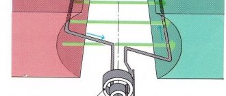
Single-phase current in its pure form is obtained using gasoline and diesel generators. In other cases, it is part of a three-phase voltage, which consists of three voltages varying according to a sinusoidal law, evenly shifted relative to each other. This time shift is called the phase angle and is 1/3T.
Four wires are used to transmit three-phase voltages. One is their common point and is called zero (N), and the other three are called phases (L1, L2, L3) .
Three-phase AC voltage graphs
The voltage between phases is called linear , and between phase and zero - phase , it is √3 times less than linear. In our network, the phase voltage is 220 V, and the linear voltage is 380 V.
The instantaneous value of alternating current voltage is understood as its value at a certain point in time t. It changes with frequency f. The instantaneous voltage value at the maximum point is called the amplitude value. But this is not what voltmeters and multimeters measure. They show a value √2 times smaller, called the effective or effective voltage value . Physically, this means that a direct current voltage of this magnitude will do the same work as the measured alternating voltage.
Characteristics of three-phase current
Advantages and disadvantages of alternating voltage
So why did they choose alternating current rather than direct current for power supply?
When transmitting electricity, current passes through wires hundreds of kilometers long, heating them and dissipating energy into the air. This is inevitable for both direct and alternating currents. But the power loss depends only on the resistance of the wires and the current in them:
The power transmitted along the line is equal to:
It follows that as the voltage increases, less current is needed to transmit the same power, and the power loss decreases. This is why the voltage is increased on long power lines. There are lines for 6kV, 10kV, 35kV, 110kV, 220kV, 330kV, 500kV, 750kV and even 1150kV.
But in the process of transferring electricity from source to consumer, the voltage must be changed repeatedly. It is easier to do this on alternating current using transformers.
The disadvantages of alternating current appear when transmitting energy through cable lines. Cables have capacitance between phases and with respect to ground, and the capacitance conducts alternating current. A leak appears, heating the insulation and causing it to fail over time.
Converting AC to DC and vice versa
The process of obtaining direct current from alternating current is called rectification , and the devices are called rectifiers . The main part of the rectifier is a semiconductor diode , which conducts current in only one direction. As a result of rectification, a pulsating current is obtained, changing its value over time, but not changing its sign.
Then the ripples are eliminated using filters , the simplest of which is a capacitor . It is impossible to completely eliminate ripple, and its final level depends on the rectifier circuit and the quality of the filter. The complexity and cost of rectifiers depends on the magnitude of the output ripple and the maximum output power.
Diagram of a simple rectifier Rectifier operation graphs
Inverters are used to convert to alternating current . The principle of their operation is to generate an alternating voltage with a shape as close as possible to a sinusoidal one. An example of such a device is a car inverter for connecting household appliances or tools to the on-board network.
The better and more expensive the inverter, the greater its power or more accurately the voltage it produces approaches a sine wave.
Rate the quality of the article:
Dependence of voltage ripple on capacitor capacitance
Let's take a practical look at why we need to install a large capacitor. In the photo below we have three capacitors of different capacities:
Let's look at the first one. We measure its value using our LC meter. Its capacity is 25.5 nanoFarads or 0.025 microFarads.
We connect it to the diode bridge according to the diagram above
And we cling to the oscilloscope:
Let's look at the oscillogram:
As you can see, the pulsations still remain.
Well, let's take a capacitor with a larger capacity.
We get 0.226 microfarads.
We connect it to the diode bridge in the same way as the first capacitor and take readings from it.
And here is the actual oscillogram
Not... almost, but still not the same. The pulsations are still visible.
Let's take our third capacitor. Its capacity is 330 microfarads. Even my LC meter cannot measure it, since my limit on it is 200 microfarads.
We hook it to the diode bridge and take an oscillogram from it.
And here she actually is
Here you go. It's a completely different matter!
So, let's draw some conclusions:
– the larger the capacitance of the capacitor at the output of the circuit, the better. But don’t overuse the capacity! Since in this case our device will be very large, because capacitors of large capacities are usually very large. And the initial charge current will be huge, which can lead to an overload of the supply circuit.
– the lower the resistance load at the output of such a power supply, the greater the ripple amplitude will appear. They combat this with the help of passive filters, and also use integrated voltage stabilizers, which produce the purest DC voltage.