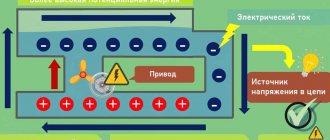
Principle of operation
How does our network voltage stabilizer, which is easy to make with your own hands, work?
After the power is turned on, capacitor C1 is in a discharged state, transistor VT2 is open, and VT2 is closed. Transistor VT3 is also closed. It is through it that current will be supplied to each LED and triac optotron.
Since this transistor is off, the LEDs are not lit, each triac is off, and the load is off. At this time, electric current passes through resistor R1 and enters C1. Next, this capacitor is charged.
The delay interval lasts only three seconds. During this time, all transient processes are carried out, and after completion, the Schmitt trigger is triggered, the basis of which is transistors VT1 and VT2.
Next, the third transistor opens and the load is turned on.
The voltage that comes out from the third winding T1 is rectified by the diode VD2 and capacitor C2. Next, the current passes through the divider R13…14. From R14, a voltage whose level is proportional to the number of volts in the network is included in each non-inverting input of the comparators.
The number of comparators is eight and they are all located on chips DA2 and DA3. At the same moment, a constant reference current enters the inverting input of each comparator. It is supplied by resistor dividers R15…23.
After this, the controller comes into play, which processes the signal at the input of each comparator.
- https://electricadom.com/stabilizator-napryazheniya-kak-vse-sdelat-svoimi-rukami-video.html
- https://amperof.ru/sovety-elektrika/sxema-stabilizatora-napryazheniya-220v.html
- https://lifehacker.ru/how-to-make-steadycam/
- https://ostabilizatore.ru/shema-stabilizatora-naprjazhenija-220v-svoimi-rukami.html
- https://fb.ru/article/360616/shema-stabilizatora-napryajeniya-v-svoimi-rukami-dlya-doma
- https://generatorvolt.ru/ehlektrogenerator/kak-sobrat-stabilizator-napryazheniya-svoimi-rukami.html
The simplest DIY electric motor speed controller
When making various homemade products, you have to face a number of problems and find solutions for them. This is the case with various devices that have a commutator electric motor in their design. Very often it is necessary to make the engine have adjustable speed. For these purposes, an engine speed regulator (controller) is used, which you can assemble yourself.
The regulator presented below for electric motors allows not only to ensure a smooth start of the motor and the degree of speed control, but also to protect the motor from overloads. The controller can operate not only from 220 Volts, but also from reduced voltage, up to 110 Volts.
How to make a phase model of a regulator?
You can make a phase current regulator with your own hands using a thyristor marked KU202. In this case, the supply of blocking voltage will proceed unhindered. Additionally, care should be taken to ensure the presence of capacitors with a maximum resistance of over 8 ohms. The fee for this case can be charged PP12. In this case, the control electrode will provide good conductivity. Pulse converters in regulators of this type are quite rare. This is due to the fact that the average frequency level in the system exceeds 4 Hz.
As a result, a strong voltage is applied to the thyristor, which provokes an increase in negative resistance. To solve this problem, some suggest using push-pull converters. The principle of their operation is based on voltage inversion. It is quite difficult to make a current regulator of this type at home. As a rule, it all comes down to finding the necessary converter.
What is a 220 V voltage regulator
The abbreviated name of the device in question is RN 0–220 V. The simplest such device is a dimmer for incandescent lamps. The device adjusts the network voltage parameters, increases/decreases the degree of the output signal in a range depending on the value of the potential difference at its output. Maintains the specified voltage of the consumer circuit.
The device regulates (smoothly or stepwise) precisely the voltage value itself, the voltage, on which the power in the range of capabilities of the connected unit also depends. It works with reactive and active loads, you just need to check whether a particular assembly is suitable, especially for the latter. And also you always need to compare what power (Watts) the circuit is designed for.
The RN changes, according to user settings, the level of the output signal from the 220 V network supplied to the load connected to it. Thus, a parameter is set that is suitable for powering a particular device, and more often for adjusting its operation (reducing/increasing the speed of low-power electric motors, light brightness).
The voltage regulator is used:
- to change the speed of small motors of household devices (the speed of a blender, hair dryer), less often, since not all circuits are suitable, for more powerful motors (for example, a drill);
- for other devices whose operation can be customized. And more often (and this is the most correct and effective use) for the light level (dimmer), sound volume, heating of heating elements, soldering iron,
- in all cases, if it is necessary to create a certain voltage on the circuit, for example, 12 V.
Most often, household pH 0–220 V is used for smooth on/off. devices.
Factory models usually also have a microcircuit for stabilizing voltage during voltage surges, ensuring the operation of devices in any mode. According to English standards, a thyristor regulator is called Voltage Controller. RNs are supplied with universal power supplies on which the voltage can be adjusted.
Types, principle of operation, features
The RN on our topic is intended only for alternating voltage, that is, for a regular 220 V home network.
Most often they are assembled based on the following parts:
- thyristors;
- triacs;
- transistors.
The circuits also contain capacitors, constant and tuning resistors. It is the selectors of the latter that carry out the adjustment. Complex assemblies may include microchips.
RNs are most effective for resistive (reactive, ohmic) loads, that is, those that are part of the power consumption of the connected/disconnected consumer. This is resistance to the flow of current, such as a resistor, at the point where electricity is converted into heat.
Resistive loads are heating elements, heating elements, incandescent lamps (not “housekeepers”).
In an inductive load, the current (where it is much lower than with a resistive load) lags behind the voltage, and reactive power is created. These are asynchronous electric motors, electromagnets, chokes, transformers, rectifiers. The launch vehicles will not work with them, or they will, but not effectively, creating a risk of equipment failure. There voltage regulators are not always appropriate.
The thyristor device cannot be used with LED (economical) and fluorescent lamps. Capacitor regulators do not allow smooth voltage changes.
Device check
The relay-regulator of the voltage of the VAZ 2106 generator, “kopecks”, and foreign cars is checked equally. As soon as you remove it, look at the brushes - they should be more than 5 millimeters long. If this parameter is different, the device must be replaced. To carry out diagnostics, you will need a constant voltage source. It would be desirable to be able to change the output characteristic. You can use a battery and a couple of AA batteries as a power source. You also need a lamp, it must run on 12 Volts. You can use a voltmeter instead. Connect the plus from the power supply to the voltage regulator connector.
Accordingly, connect the negative contact to the common plate of the device. Connect a light bulb or voltmeter to the brushes. In this state, voltage should be present between the brushes if 12-13 Volts are supplied to the input. But if you supply more than 15 Volts to the input, there should be no voltage between the brushes. This is a sign that the device is working properly. And it doesn’t matter at all whether the voltage regulator relay of the VAZ 2107 generator or another car is diagnosed. If the control lamp lights up at any voltage value or does not light up at all, it means that there is a malfunction of the unit.
Practical examples for review
The most popular among radio amateurs are circuits designed to control the brightness of a lamp and change the power of a soldering iron. Such circuits are easy to repeat and can be assembled without the use of printed circuit boards by simple overhead mounting.
Circuits made independently are in no way inferior in performance to factory ones, since they do not require settings and, with working radio components, are immediately ready for use. If you are unable or want to make the device yourself from scratch, you can purchase kits for self-production. Such kits contain all the necessary radio elements, a printed circuit board and a circuit with assembly instructions.
Dominant scheme
The easiest way to assemble such a device is with a thyristor. The operation of the circuit is based on the ability of the thyristor to open when the input sinusoid passes through zero, as a result of which the signal is cut off and the voltage across the load changes.
The circuit for replicating the thyristor power regulator is based on the use of thyristor VS1, which is used as KU202N. This radio element is made of silicon and has a pnp type structure. Used as a symmetrical switch for medium power signals and switching AC power circuits.
When a voltage of 220V is applied, the input signal is rectified and sent to capacitor C1. As soon as the voltage drop across C1 is equal to the potential difference, at the point between resistances R3 and R4, bipolar transistors VT1 and VT2 open. The voltage level is limited by the zener diode VD1. The signal is sent to the control terminal of KU202N, and capacitor C1 is discharged. When a signal occurs at the control terminal, the thyristor is unlocked. As soon as the capacitor is discharged, VT1 and VT2 close, and the thyristor also closes accordingly. At the next half-cycle of the input signal, everything repeats again.
Such a regulator can be used not only as a dimmer, but also to control the power of a commutator motor. The dominant circuit can operate at currents up to 10 amperes; this value directly depends on the characteristics of the thyristor used, and it must be installed on the radiator.
Soldering iron heating controller
Controlling the power of a soldering iron not only has a positive effect on its service life, preventing the tip and its internal elements from overheating, but also allows you to solder radioelements that are critical to the temperature of the device.
Devices for monitoring the temperature of a soldering iron have been produced for a long time. One of its types was a domestic device, produced under the name “Additional device for an electric soldering iron type P223.” It allowed connecting a low-voltage soldering iron to a 220V network.
The easiest way to make a regulator for a soldering iron is to use a KU208G triac.
Power contacts are connected in series to the load. Therefore, the current flowing through the triac coincides with the load current. To control the key mode, dinistor VS2 is used. Capacitor C1 is charged through resistors: R1 and R2. Operation indication is organized using VD1 and LED. Because it takes time for the voltage across the capacitor to change, a phase shift occurs between the mains voltage and the capacitor voltage. By changing the value of resistance R2, the magnitude of the phase shift is adjusted. The longer the capacitor is charged, the less the triac is in the open state, and therefore the power value is lower.
This regulator is designed to connect a load with a power of up to 300 watts. When using a soldering iron with a power of more than 100 watts, the triac should be installed on a radiator. The manufactured board easily fits on a PCB measuring 25x30 mm and is freely placed in an internal power socket.
Electrical circuits use a voltage regulator to change the output level. Its main purpose is to change the power supplied to the load. Using the device, they control the speed of electric motors, the level of illumination, sound volume, and heating of devices. You can buy a finished product in radio stores, but it’s easy to make a voltage regulator yourself.
DC devices
The DC regulator circuit is characterized by high conductivity. At the same time, heat losses in the device are minimal. To make a constant current regulator, the thyristor requires a diode type. The pulse supply in this case will be high due to the rapid voltage conversion process. The resistors in the circuit must be able to withstand a maximum resistance of 8 ohms. In this case, this will minimize heat losses. Ultimately, the modulator will not overheat quickly.
Modern analogues are designed for approximately a maximum temperature of 40 degrees, and this should be taken into account. Field-effect transistors are capable of passing current in a circuit only in one direction. Taking this into account, they must be located in the device behind the thyristor. As a result, the level of negative resistance will not exceed 8 ohms. High-frequency filters are rarely installed on a DC regulator.
Purpose
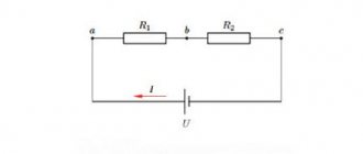
Voltage booster transformers (linear regulators) are used to regulate voltage in individual lines or in a group of lines. They are used, for example, to improve the operation of networks that use transformers without load regulation. Linear regulators allow you to create an additional EMF in the network, which adds up to the network voltage vector and changes it. In Fig. Figure 1 shows a schematic representation of a boost transformer (linear regulator).
Figure 1 – Schematic representation of a linear regulator
Installing a voltage booster transformer allows you to equalize the voltage in the electrical network; eliminate voltage asymmetry in a certain section of the circuit; reduce the dangerous consequences of burning out the neutral conductor
Thyristor converter – motor
It received its massive development in the 60s, when thyristors began to appear. It was on their basis that the first static low-power thyristor converters were created. Such devices were connected directly to AC networks:
Voltage regulation occurs by changing the opening angle of the thyristor. Regulation through a thyristor converter has a number of advantages over the generator-motor installation, such as high speed and efficiency, smooth regulation of DC voltage and many others.
Chip contacts
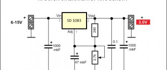
Manufactured in a universal transistor package, allowing it to be placed on a board or heat sink. The most common model LM317 is found in the TO-220 case with the letter “T” at the end of the marking. The letter "t" indicates the housing type.
The pinout of the LM317 stabilizer is made using three contacts. If you look at the device from the front, the first pin on the left (Adj) is the adjustable pin, the middle pin (Vout) is the output, and the last pin on the right (Vin) is the input.
- Vin is a pin; it receives an input voltage that needs to be adjusted. For example, it may be supplied with 12V, which the device will step down to 10V at Vout.
- Vout is the pin to which the voltage is output. The surface of the heatsink is connected to this pin of the microcircuit.
- Adjustable (Adj) is a pin that allows you to adjust the output voltage through a trimmer resistor.
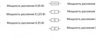
Found in various types of housings.
Contact numbers of different types of microcircuit housings.
Soft start models
In order to design a thyristor current regulator with soft start, you need to take care of the modulator. Rotary analogues are considered to be the most popular today. However, they are quite different from each other. In this case, much depends on the board used in the device.
If we talk about modifications of the KU series, they work on the simplest regulators. They are not particularly reliable and do cause some glitches. The situation is different with regulators for transformers. There, as a rule, digital modifications are used. As a result, the level of signal distortion is significantly reduced.
Basic functions of the speed controller
The use of such converters allows you to achieve many goals, namely:
- the possibility of stepwise acceleration and reduction of electric motor speed, which leads to reduced loads and less electrical energy consumption;
- you can carry out a smooth start, and with instantaneous maximum acceleration, the motor receives ultra-high loads, overheating the windings and other drives;
- as a means of additional protection of electronic mechanisms;
- reduction in maintenance costs for power units and pumps, as the risks of drive failures, as well as individual mechanisms, are reduced.
Welding machines, voltage stabilizers, PCs, TVs, etc. cannot do without similar built-in devices.
Resistor power calculation
I mentioned earlier that resistors are made in a variety of standard wattage ratings - 0.25W, 0.5W, 1W, etc. I suggested that you buy resistors that are 0.25W or higher. How did I know this?
Let's go back to the LED circuit. Remember, we wanted a voltage drop across the resistor of 3.5V and a current of 20mA. How much power is dissipated by this resistor?
Write down what you know:
U = 3.5 V (voltage drop across resistor)
I = 20 mA = 0.02 A (current flowing through resistor)
We want to know the power in watts, so we use the formula where power is on the left side of the equation:
W = U × I.
Now you need to substitute the values into this formula:
W = 3.5 V × 0.02 A = 0.07 W (power dissipated by the resistor)
Thus, we found that the 0.25 W (1/4 watt) resistor we used has almost 4 times the power it actually dissipates. We could actually use 0.125W (1/8 watt) resistors here, but for future experiments we will need 0.25W resistors. Therefore, in this case, precisely such resistors are used, since there are no restrictions on the use of a resistor designed for a power greater than that which is actually dissipated by it.
Construction and details
Now let's move on to the design of the device. Diode bridges, a capacitor, resistor R2 and diode VD6 are installed on a circuit board measuring 55x35 mm, made of foil getinax or textolite with a thickness of 1...2 mm (Fig. 9.7).
The following parts can be used in the device. Transistor - KT812A(B), KT824A(B), KT828A(B), KT834A(B,V), KT840A(B), KT847A or KT856A. Diode bridges: VD1...VD4 - KTs410V or KTs412V, VD6 - KTs405 or KTs407 with any letter index; diode VD5 - series D7, D226 or D237.
Variable resistor - type SP, SPO, PPB with a power of at least 2 W, constant - BC, MJIT, OMLT, S2-23. Oxide capacitor - K50-6, K50-16. Network transformer - TVZ-1-6 from tube TVs, TS-25, TS-27 - from the Yunost TV or any other low-power one with a secondary winding voltage of 5...8 V.
The fuse is designed for a maximum current of 1 A. The toggle switch is TZ-S or any other network switch. XP1 is a standard power plug, XS1 is a socket.
All elements of the regulator are housed in a plastic case with dimensions of 150x100x80 mm. A toggle switch and a variable resistor equipped with a decorative handle are installed on the top panel of the case. The socket for connecting the load and the fuse socket are mounted on one of the side walls of the housing.
On the same side there is a hole for the power cord. A transistor, transformer and circuit board are installed at the bottom of the case. The transistor must be equipped with a radiator with a dissipation area of at least 200 cm2 and a thickness of 3...5 mm.
Rice. Printed circuit board of a powerful 220V mains voltage regulator.
The regulator does not need to be adjusted. With proper installation and serviceable parts, it begins to work immediately after being plugged into the network.
Now some recommendations for those who want to improve the device. The changes mainly concern increasing the output power of the regulator. So, for example, when using the KT856 transistor, the power consumed by the load from the network can be 150 W, for KT834 - 200 W, and for KT847 - 250 W.
If it is necessary to further increase the output power of the device, several parallel-connected transistors can be used as a control element by connecting their corresponding terminals.
Probably, in this case, the regulator will have to be equipped with a small fan for more intensive air cooling of semiconductor devices. In addition, the diode bridge VD1...VD4 will need to be replaced with four more powerful diodes, designed for an operating voltage of at least 600 V and a current value in accordance with the consumed load.
Devices of the D231...D234, D242, D243, D245...D248 series are suitable for this purpose. It will also be necessary to replace VD5 with a more powerful diode, rated for current up to I A. Also, the fuse must withstand a higher current.
Triac power regulators operate using phase control. They can be used to change the power of various electrical devices operating using alternating voltage.
The devices may include electric incandescent lamps, heating devices, alternating current electric motors, transformer welding machines, and many others. They have a wide range of adjustment, which gives them a wide range of applications, including in everyday life.
Schematic diagram
The transistor voltage regulator (Fig. 9.6) contains a minimum of radio elements, does not interfere with the electrical network and operates on a load with both active and inductive resistance. It can be used to adjust the brightness of a chandelier or table lamp, the heating temperature of a soldering iron or hotplate, the rotation speed of a fan or drill motor, and the voltage on the transformer winding. The device has the following parameters: voltage adjustment range - from 0 to 218 V; the maximum load power when using one transistor in the control circuit is no more than 100 W.
The regulating element of the device is transistor VT1. The diode bridge VD1...VD4 rectifies the mains voltage so that a positive voltage is always applied to the collector VT1. Transformer T1 reduces the voltage of 220 V to 5...8 V, which is rectified by the diode unit VD6 and smoothed by capacitor C1.
Rice. Schematic diagram of a powerful 220V mains voltage regulator.
Variable resistor R1 serves to adjust the control voltage, and resistor R2 limits the base current of the transistor. Diode VD5 protects VT1 from negative polarity voltage reaching its base. The device is connected to the network using an XP1 plug. The XS1 socket is used to connect the load.
The regulator operates as follows. After turning on the power with toggle switch S1, the mains voltage is supplied simultaneously to diodes VD1, VD2 and the primary winding of transformer T1.
In this case, a rectifier consisting of a diode bridge VD6, a capacitor C1 and a variable resistor R1 generates a control voltage that goes to the base of the transistor and opens it. If at the moment the regulator is turned on, there is a voltage of negative polarity in the network, the load current flows through the circuit VD2 - emitter-collector VT1, VD3. If the polarity of the mains voltage is positive, current flows through the circuit VD1 - collector-emitter VT1, VD4.
The value of the load current depends on the value of the control voltage based on VT1. By rotating the R1 slider and changing the value of the control voltage, the magnitude of the collector current VT1 is controlled. This current, and therefore the current flowing in the load, will be greater the higher the control voltage level, and vice versa.
When the variable resistor motor is in the extreme right position according to the diagram, the transistor will be completely open and the “dose” of electricity consumed by the load will correspond to the nominal value. If the R1 slider is moved to the extreme left position, VT1 will be locked and no current will flow through the load.
By controlling the transistor, we actually regulate the amplitude of the alternating voltage and current acting in the load. At the same time, the transistor operates in continuous mode, due to which such a regulator is free of the disadvantages inherent in thyristor devices.
DIY soldering iron power regulator: proven working circuits (6 pcs)
Not everyone likes to buy unknown things. And some people find it more pleasant to make a soldering iron power regulator with their own hands, because this is also experience. Most circuits are assembled using triacs and thyristors; now they are easier to find than transistors. They are also easier to work with, since they are either open or closed, which allows you to make circuits simpler.
Choose any case
Simple thyristor circuits
When choosing a power regulator circuit for a soldering iron, two things are important: power and parts availability. The soldering iron power regulator presented below is assembled using widely used parts that are not a problem to find. The maximum current is 10 A, which is more than enough to perform any kind of work and for soldering irons with a power of up to 100 W. The thyristor in this circuit is used KU202n
Pay attention to the bridge connection. There are many circuits with connection errors. This option works
Tested more than once
This option is working. Tested more than once.
Temperature controller circuit for a soldering iron using a thyristor
When assembling the circuit, be sure to place the thyristor on the radiator; the larger it is, the better. The circuit is simple, but when it is turned on, it creates interference. You can’t listen to the radio nearby, and to remove interference, we connect a 200 pF capacitor in parallel with the load, and a choke in series. The choke parameters are selected depending on the regulated load, but since soldering irons are usually no more than 80-100 W, the choke can be made at 100 W. To do this, you will need a ferrite ring with an outer diameter of 20 mm, on which about 100 turns are wound with a wire with a cross-section of 0.4 mm².
Another drawback of the diagram translated above is that the soldering iron “itches” noticeably. Sometimes you can put up with this, sometimes you can’t. To eliminate this phenomenon, you can select the parameters of capacitor C1 so that when the variable resistor is set to maximum, the connected lamp barely glows.
On other elements but also without interference
The above regulator can be used for any load. Let's give another analogue, but using a different element base. You can regulate not only the power/temperature of the soldering iron, but also any other load with a small inductive component.
A modified circuit for regulating the power of a soldering iron and any other load with the ripple effect eliminated
There is pulsation here, but its frequency is high and it will not be perceived by our vision. So it can be used not only as a dimmer for a soldering iron, but also to regulate the light from a regular incandescent lamp. Is a diode bridge needed to regulate the heating power of a soldering iron? It won't hurt, but it's not necessary.
On a thyristor with high sensitivity
This circuit allows you to smoothly change the temperature of the soldering iron from 50% to 100%. There are two indicators - power and power. The power presence LED always lights up when turned on, but at 75% power the glow is brighter. The power indicator changes the intensity of the glow depending on the operating mode.
Power regulator for soldering iron without interference
In order for the regulator to fit into the case of a mobile phone charger, resistances are used of SMD type (1206). All resistors are installed on the board, except for R 10. Some can be composite (we assemble the required value from series-connected resistors).
For normal operation of the circuit, a sensitive thyristor (with a low control current) and a low state holding current (about 1 mA) is required. For example, KT503 (designed for voltage 400 V, control current 1 mA). The rest of the element base is indicated in the diagram.
If assembled, but the voltage is not adjustable
If the assembled regulator does not regulate anything - the temperature of the soldering iron does not change - the problem is in the thyristor. The scheme seems to be working, but nothing happens. The reason is a thyristor with low sensitivity. The currents flowing in the circuit are not sufficient to open. In this case, it is worth installing an analogue with higher sensitivity (lower control currents).
One of the housing options in which you can hide a homemade power regulator for a soldering iron
The regulator may still work, but the soldering iron begins to “itch.” This problem is solved by installing a choke at the output (in front of the soldering iron). The capacity must be selected - it depends on the soldering iron. The second solution is an analog control circuit, and this is a different circuit.
Well, if you have problems with operation, look for either faulty parts or incorrectly selected components. This is usually the problem.
Scheme number 1
There was a stabilized switching power supply that gave an output voltage of 17 volts and a current of 500 milliamps. A periodic change in voltage was required in the range of 11 - 13 volts. And the well-known voltage regulator circuit on one transistor coped with this perfectly. I added only an indication LED and a limiting resistor to it. By the way, the LED here is not only a “firefly” signaling the presence of output voltage. With the correct value of the limiting resistor, even a small change in the output voltage is reflected in the brightness of the LED, which provides additional information about its increase or decrease. The output voltage could be changed from 1.3 to 16 volts.
KT829, a powerful low-frequency silicon compound transistor, was installed on a powerful metal radiator and it seemed that, if necessary, it could easily withstand a heavy load, but a short circuit occurred in the consumer circuit and it burned out. The transistor has a high gain and is used in low-frequency amplifiers - you can really see its place there and not in voltage regulators.
On the left are removed electronic components, on the right are prepared for replacement. The difference in quantity is two items, but in terms of the quality of the circuits, the former and the one that was decided to be collected, it is incomparable. This begs the question: “Is it worth assembling a scheme with limited capabilities when there is a more advanced option “for the same money”, in the literal and figurative sense of this saying?”
Generator voltage regulator
The generator converts electricity. Without a generator, the entire on-board system of the car would not work. A special sensor is connected to the magnet winding. Simple springs are the driving device. A small lever is used for the comparison device. The group of contacts plays the role of an actuator. A constant resistance is an adjustment element that is often used in machines.
During operation of the generator, a current arises at its output. The resulting current passes into the winding of the magnetic relay. As a result, a magnetic field appears and, under its influence, the lever arm moves apart. A spring begins to act on it and plays the role of a comparing device. When the current exceeds the required values, the contacts on the magnetic relay move apart. At this time, the constant resistance in the circuit is turned off. Less current flows into the winding.
Perhaps it is useful for everyone to know what the accuracy class of an electric meter is.
Switching DC-DC converters
These are perhaps the most modern control devices in DC circuits. It can be compared to a transformer, since the behavior of a pulse converter is similar to a transformer with a smoothly varying number of turns:
Such systems actively replace electric drives with resistive regulation, by connecting them to the machine armature in series, instead of a resistive-contactor group. I use them quite often in electric cars, and they have also gained quite a lot of popularity in underground transport (subway). Such converters emit minimal heat, which does not heat up the tunnels and can implement regenerative braking mode, which is a big plus for electric drives with frequent starting and braking.
The big advantage of such devices is that they can recuperate energy into the network, smoothly regulate the rate of current rise, and have high efficiency and speed.
From the network
Single-phase AC motors also allow you to control the rotation of the rotor.
Collector machines
Such motors are found on electric drills, jigsaws and other tools. To reduce or increase the speed, it is enough, as in previous cases, to change the supply voltage. There are also solutions for this purpose. The structure connects directly to the network. The adjusting element is a triac, which is controlled by a dinistor. The triac is placed on the heat sink, the maximum load power is 600 W.
If there is a suitable LATR, you can do all this using it.
Two phase motor
The device, which has two windings - starting and working, is two-phase in principle. Unlike three-phase, it has the ability to change the rotor speed. The characteristic of its rotating magnetic field is not circular, but elliptical, which is due to its design. There are two possibilities for controlling the speed:
- Change the amplitude of the supply voltage (Uy),
- Phase - change the capacitance of the capacitor.
Such units are widely used in everyday life and in production.
Regular asynchronous
Three-phase electric machines, despite their ease of operation, have a number of characteristics that need to be taken into account. If you simply change the supply voltage, the torque will change within a small range, but no more. In order to regulate speed within a wide range, you need quite complex equipment, which is difficult and expensive to simply assemble and set up.
For this purpose, the industry has launched the production of frequency converters that help change the speed of the electric motor in the desired range.
The asynchronous machine gains momentum in accordance with the parameters set on the frequency driver, which can be changed in a wide range. The converter is the best solution for such engines.
Generator-engine system
In such a system, the required voltage level is formed by changing the excitation flow of the generator:
The presence of three electric machines in such a system, large weight and dimensions and a long repair time in case of breakdowns, as well as expensive maintenance and the large inertia of such an installation made the efficiency of such a machine very low. Nowadays there are practically no generator-motor systems left; they are all being actively replaced by thyristor converter systems - TP-D motor, which has a number of advantages.
How to avoid 3 common mistakes when working with a triac.
- The letter after the triac code indicates its maximum operating voltage: A – 100V, B – 200V, C – 300V, D – 400V. Therefore, you should not take a device with the letters A and B to adjust 0-220 volts - such a triac will fail.
- A triac, like any other semiconductor device, gets very hot during operation; you should consider installing a radiator or an active cooling system.
- When using a triac in load circuits with high current consumption, it is necessary to clearly select the device for the stated purpose. For example, a chandelier with 5 bulbs of 100 watts each will consume a total current of 2 amperes. When choosing from the catalog, you need to look at the maximum operating current of the device. Thus, the MAS97A6 triac is designed for only 0.4 amperes and will not withstand such a load, while the MAS228A8 is capable of passing up to 8 A and is suitable for this load.
Remote controller
ATTENTION! A completely simple way to reduce fuel consumption has been found! Don't believe me? An auto mechanic with 15 years of experience also didn’t believe it until he tried it. And now he saves 35,000 rubles a year on gasoline! Read more"
This often happens to drivers. The brushes of the generating device burn out. The regulator is built in along with the brushes. We have to change everything together. And here’s some advice from experts: it’s better to install an external regulator than a built-in one. The models released recently have not been praised very much.
Okay, do you think I’ll install an external one, but how do I connect it? It turns out that there is a convenient scheme that makes it easy to carry out all this modernization.
Some important points:
- do not confuse the chips on the regulator numbered 67 and 15 (the first should be connected to the generating device, and the second should go to the fuses);
This is what the connection diagram looks like
In the lower photo we see a diagram that shows the connection of the already built-in regulator relay.
It is suitable for connecting to “fives”, “sevens”, VAZ 2104, if the PG is installed from a VAZ “kopek”. As you can see, the remote-type regulator relay is connected via two terminals. Pin 15 goes to the fuse.
The second pin 67 is connected to the generator. The wire is connected to the brush chip.
Also, the remote-type relay must be connected to ground - any part of the body.
A relay is nothing more than a switch that serves to close and disconnect individual zones of an electrical circuit that occur at specific electrical values. A machine relay is otherwise called a load voltage switch, and this is 100 percent true. When the power supply unit, fan or starter consumes more current than necessary, the relay trips.
The relay consists of an electric type magnet, an armature and a switch. In this case, the electromagnet is a cable twisted around an inductor with a magnetic rod, and the armature is a special plate that controls the contacts.
As soon as electrical voltage passes through the magnet winding, an electric field is created. A special pusher presses the armature against the core and, thereby, the contacts switch.
Attention. There are two types of relays used on VAZ cars. This is a non-contact relay-regulator and MER (electric). It is the diagram of the last relay that is shown in the picture below.
The non-contact relay or NERR is a fairly new unit that does not require any additional adjustments or regulation. As for the MED, this is an old-style device, the production of which has currently been suspended.
So, the BRN or built-in regulator is a device consisting of a microcircuit, a transistor and a housing with brushes. If the built-in regulator fails, it is replaced with a new one, or an external one is installed.
The external regulator is easy to install if you strictly follow the instructions.
Modernization involves dismantling and disassembling the generating device.