While the transformer is operating in an electrical installation, it gradually loses its original properties, and without proper maintenance it will simply fail. This comes from the constant negative influence of electrodynamic, thermal and mechanical loads. In order to prevent failure of any transformer, it is necessary to carry out, in addition to daily external inspection, the following types of repairs:
- Current;
- Capital.
They are scheduled preventative maintenance. There is another special type of repair - extraordinary. It is carried out if a defect is detected if it can lead to failure. This decision is not made by ordinary electrical personnel; this must be done either by the Consumer’s manager or by the person responsible for the electrical equipment of a given workshop or site. The staff only reports to their management about malfunctions.
One of the most common types of transformers in production has the abbreviation TMG (oil sealed transformer) and is used in almost all types of substations and distribution devices. Repairing windings and servicing them is a very difficult task, since just to inspect them you need to drain all the oil and disassemble the hermetically sealed housing.
Who sets the frequency of current transformer repairs?
Depending on local operating conditions, as well as the condition of the transformer, routine repairs are carried out as necessary. Their frequency is established by the technical manager or the person responsible for electrical equipment. Most often, these works are performed at least once a year. Sometimes this period can be extended to once every three years. Major renovations are a slightly different story. Major repairs are carried out according to the standard nomenclature of work and should be carried out:
- For transformers of 110 kV and above, with a power of 125 MVA and more, no later than 12 years after its commissioning. This is done taking into account the results of diagnostic control. Further repairs are made as necessary;
- All other less powerful transformers (TMG) are subject to major repairs in accordance with their condition and based on the results of diagnostic control.
Design and purpose of units
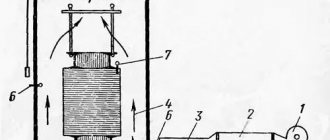
Transformers are used to convert alternating electric current of a certain frequency and voltage into electric current with the same frequency but a different voltage. Each device is based on the phenomenon of electromagnetic induction discovered by Faraday. If we talk about the purpose and design of the transformer, then it is used in almost all power supply circuits for electrical appliances, and also transmits energy over long distances. The equipment is capable of creating a voltage of 220, 380 or 660 V, which is widely used at both the domestic and industrial levels.
The device, in general, may vary depending on the specific type of unit: pulse, current or power. The latter are the most common and are most often found in various places. The simplest option for the purpose and design of the transformer assumes the presence of one phase. As part of such a device, you can find a metal core and a pair of windings, each of which is an independent insulated wire. The transformer is connected to an alternating current source. The connection occurs using the primary winding, and the other, the secondary, is used to power the consumer.
Output for repair of a power transformer sequence
The task and features of grounding transformers.
During operation, any transformer, step-down or step-up, is taken out of operation emergency in the following cases:
- Internal crackling, which is characteristic of an electrical discharge between two oppositely polarized conductors;
- Abnormal or uneven noise that occurs both with and without load;
- In case of unreasonable heating, which increases even with rated load and proper cooling;
- In case of oil emissions, which can be from the expander or from a damaged exhaust pipe diaphragm;
- In case of severe oil leakage, as well as when the minimum permissible level is reached;
- After receiving bad results from a chemical analysis of the oil from the laboratory.
The sequence of actions of personnel when taking a transformer out of service for repair is clearly regulated and signed. Depending on local conditions and the switching circuit of the transformers, these switchings may differ slightly from each other, but the basic logical chain still remains the same. The main thing is that they must be carried out without consequences for the powered equipment and for sources consuming electricity, and also safely, that is, using both basic and additional personal protective equipment.
Here is the sequence of shutdowns and switchings in the circuit of a step-down three-phase oil or dry transformer of a substation in order to take it out for repair:
- If there is a sectional disconnector and an oil switch on the low side, then to ensure uninterrupted power supply to power consumers. in this case, the disconnector is turned on first and only then the sectional oil switch;
- The oil switch is turned off on the low side. Now both sections are powered by one transformer, which will power both sections during the repair of the other. Naturally, this is if there are only two of them, like transformers;
- The input oil switch is turned off, that is, on the high side;
- Now it is possible to provide a visible break to the power buses of a transformer being taken out for repair by disconnecting the linear or bus disconnectors;
- Portable grounding connections must be installed on the low and high sides, naturally, after directly checking the absence of voltage and posting safety posters.
After that, a team is allowed to visit the transformer being repaired, in compliance with all organizational and technical measures.
How the device works
Carrying out any technical work may also depend on a certain type of unit. The simpler the design, the less maintenance is required, and the process itself is somewhat easier. Possible types of work depend on a number of technical parameters of the transformer: the number of windings and the number of phases.
Converted current flows continuously through the connected device. In this case, the magnetic flux penetrates all the windings and induces an EMF in them. There is also an idle mode. In this case, the secondary winding is deprived of any load. This example generally illustrates the operation of a simple single-phase transformer.
Current repairs of power transformers
Features of the application and selection of measuring current transformers
The scope of work performed during routine repairs includes:
- Thorough external inspection;
- Cleaning the body, wiping insulators;
- Tightening of all bolted connections, special attention should be paid to current-carrying connections; if they are oxidized, they must be unscrewed, cleaned and re-tightened;
- Checking the cooling system and the operation of the oil indicator device;
- Activation of gas protection and cleaning of block contacts in it;
- If there are automatic cooling devices, it is necessary to check their operation and functionality;
- Draining water and condensate from the expander sump;
- Checking the moisture level of silica gel. Pink particles must be replaced with new ones;
- Add oil to the expansion tank if necessary;
- Measuring the insulation resistance, this procedure is performed with a megger rated for a voltage of 2500 Volts. The instrument error should not exceed 10–15%.
If minor faults are noticed between routine repairs during operation, they must be corrected by repair personnel. In this case, the number of components and parts that must be replaced with new ones should be minimal.
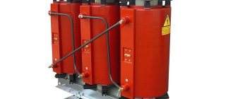
During routine repairs of dry transformers, it is necessary to remove the casing and make sure that there is no electrical heating or mechanical damage to all its parts. After covering, be sure to blow with compressed air, only after that put the casing back. Repair of a pulse transformer due to its small dimensions can be carried out even at home.
Transformer Maintenance Composition
The scope of maintenance of transformer equipment involves periodic performance of the following work:
- external visual inspection;
- checking significant technical characteristics;
- remote control of temperature parameters;
- carrying out instrumental measurements of the necessary parameters;
- analysis of the condition of materials, including the composition of transformer oil;
- checking the integrity and reliability of welding, bolted, rivet connections, insulating elements, and ground loop;
- changes in the resistance value of the insulating coating;
- monitoring the performance of automatic switching devices;
- measurements in the phase-zero loop, short circuit currents;
- checks for switching to a backup energy source;
- control of automatic systems, the condition of the building where the equipment is located, the availability of protective equipment.
Within the scheduled time limits, it is necessary to test the units, providing for the supply of a load exceeding the rated load, in the manner established by state regulations.
Also read: What is the absorption coefficient of a transformer
Overhaul of power transformers
Features of the application and design of welding transformers
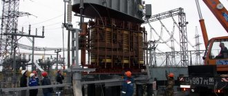
During a major overhaul, the cover must be opened and all components thoroughly checked. After which it is tested in accordance with regulatory documents. Repair of large power oil transformers (TMG) is carried out directly at the installation site using prefabricated structures, without sending it to a repair shop. If there are transformer towers built near switchgears or repair areas of machine rooms with access roads, then they will also be used. Repair of oil transformers (TMG) should include a complete replacement of old oil with new one.
Low power transformers (welding, pulse, etc.) are repaired in specially equipped workshops or repair shops. These premises must reliably protect disassembled transformers from dust and various atmospheric precipitations getting on their parts. Types of particularly important work that should only be performed by highly specialized workers with the skills and knowledge:
- Delivery of TMG to the repair site. Its loading, unloading and transportation;
- Removing contact terminals;
- Repair of the active part of the transformer;
- Moving and installing individual components and assemblies.
Moreover, workers must be able to efficiently perform not only electrical work, but also rigging. After completing the appropriate training, passing exams, and also receiving a supporting document. The technological process of repairing a transformer must be carried out efficiently and strictly according to schedule; then this unpretentious equipment will last for decades. Testing a transformer after repair comes down to:
- determination of the transformation ratio. It is defined for all existing windings and branches;
- measuring the insulation resistance of windings;
- supplying increased voltage to the primary winding. Each winding is subjected to this test. The technology of this process is performed using a step-up autotransformer. It is this that makes it possible to increase and decrease the test voltage smoothly
CHAPTER EIGHT
REPAIR OF TRANSFORMERS
8.1. TYPES AND FREQUENCY OF REPAIRS
Domestic transformers are simple in design and reliable in operation. Their specific damage rate compared to other types of equipment is insignificant. However, to troubleshoot problems and prevent accidents, transformers are periodically put out for routine and major repairs.
The scope of current transformer repairs includes external inspection, cleaning, and elimination of identified damage. At the same time, the condition of valve seals, cooling systems, the operation of the oil indicator, the operation of gas protection, and the operation of automatic devices in cooling and fire extinguishing systems are checked. Moisture and sediments falling from the oil descend from the expander sump. The degree of moisture content of silica gel in the air purifier, adsorption and thermosiphon filters is checked. Silica gel is replaced if pink grains are found in the mass of purple-colored indicator silica gel grains. The oil in the oil seal of the air dryer is replaced; oil samples are taken from the transformer and oil-filled bushings. The operation of voltage regulation devices is checked. The nitrogen protection system is inspected.
During routine repairs of transformers, the insulation resistance of the windings is usually measured and the ratio /?bo"/#i5" is determined. Measurements are carried out using a megohmmeter with a voltage of 2500 V.
Routine repairs of the main transformers of stations and substations, main and backup transformers for own needs are carried out at least once a year, if these transformers are equipped with an on-load tap-changer, in the absence of an on-load tap-changer - at least once every 2 years.
During a major overhaul, the transformer is opened, a thorough inspection and repair of all its components and tests are carried out.
Under operating conditions, major overhauls of large transformers are carried out at the installation site using prefabricated structures, in transformer towers built near switchgears, at repair sites in the electrical machine room.
stations with access roads from transformer installation sites. Low-power transformers are repaired in the electrical workshops of power plants.
Premises for repairs, as well as temporarily constructed shelters, must reliably protect transformers from dust and precipitation. Carrying out rigging work requires special knowledge and skills from repairmen. Therefore, delivering the transformer to the repair site, removing the bushings, lifting the active part and moving individual parts and assemblies is entrusted to specialist riggers.
Overhaul of the main transformers of power plants and substations, the main transformers for the auxiliary needs of power plants is carried out for the first time no later than 8 years after putting into operation, taking into account the results of preventive tests, and in the future - as necessary, depending on the condition of the transformer.
8.2. CONDITIONS FOR OPENING TRANSFORMERS FOR REPAIR
Moistening of the transformer insulation during repair occurs as a result of the absorption of moisture contained in the air. If the temperature of the active part of the transformer is lower than the ambient temperature, then when the air comes into contact with the relatively cold active part, moisture condenses on its surface and is absorbed by the insulation. In order to prevent the insulation from getting wet during repairs and to put the transformer into operation without drying, inspection and repair of its active part must be carried out in dry, clear weather. In this case, the active part is allowed to be kept in air with a relative humidity of less than 75% for no more than 24 hours for transformers up to 35 kV inclusive and 16 hours for transformers PO - 500 kV.
The time is counted from the beginning of draining the oil from the transformer. The temperature of the active part during repairs must exceed the dew point temperature of the ambient air by at least 10 °C. If this condition cannot be met, opening the transformer is postponed or the active part is heated to a temperature exceeding the ambient air temperature by 10-15 ° C. In the event
In rainy weather, the inspection is carried out in a room where the air temperature is maintained above the outside air temperature by at least 10 °C. The residence time of the active part in the air can be increased (no more than twice as compared to that indicated above), but in this case the ambient temperature must be above 0°C, the relative humidity less than 75%, and the temperature* of the active part must exceed the ambient temperature air at least 10 °C. If the active part is exposed to air for a longer period of time, as indicated above, control drying or drying of the insulation will be required, the need for which is established based on the results of measurements of the insulation characteristics.
8.3. SCOPE OF WORK PERFORMED
WHEN OVERHAULING TRANSFORMERS
110 kV AND HIGHER
Overhaul of a transformer without disassembling its active part includes the following stages of work: disassembling auxiliary equipment; lifting the removable part of the tank (bell) or the cover and active part (for transformers with an upper tank connector) and installing them on the repair site; inspection and repair of the active part; inspection and repair of auxiliary equipment; control drying or drying of the insulation of the active part; tests.
Disassembly of auxiliary equipment.
Before disassembling, the transformer is inspected from the outside, it is found out what malfunctions were observed during operation, the operation of the cooling systems and winding tap switching devices is checked; inspect reinforcement, welds, reinforcement of insulators, seals and draw up an inventory of external defects. Then the insulation characteristics /?6o7^i5″, tgS, C2/C5o are measured, an abbreviated analysis is carried out and measurement of tg 6 of the oil from the tank. Then the oil is drained from the tank with air suction through a dryer and the AC/C insulation of the transformer is measured.
After completing the specified work, control devices, protection devices, automation and cooling system control devices are dismantled. The removed devices are sent to the laboratory for testing.
Next, remove the expander, safety pipe, thermosiphon filter and coolers. Disconnect and
remove oil-filled MV, HV and LV bushings using special traverses. Before removal, the LV inputs are disconnected from the flexible outlets through hatches.
Lifting the removable part.
Before lifting the removable part, loosen and remove the bolts evenly around the entire perimeter of the tank connector. Release the spacer bolts between the tank and the active part. They sling the tank cover or bell, lift them using a winch or crane and install them on the repair site. For powerful transformers with a bottom connector, the active part is exposed when the bell is removed. For repairs, it usually remains on the pallet. For transformers whose tanks have an upper connector, the active part is removed from the tank and installed at the repair site.
Inspection and repair of the active part.
During repairs, the condition of the insulation of windings, pressing parts of windings, bends and bolted connections, insulating cylinders, barriers and partitions is checked; magnetic circuit and its grounding, insulation of tie rods, pressing rings of yoke beams and bandages; winding tap switch.
To inspect the windings and magnetic circuit of the transformer, it is necessary first of all to dismantle the insulating partitions and other elements of its main insulation. When removing partitions, you should check whether they touch the windings and taps, and whether there are any traces of electrical discharges between them. The main insulation is checked by external inspection and is considered suitable for further use if the electrical cardboard is not fragile and does not break when bent in half. Bakelite cylinders are inspected and checked to see if there are any cracks on their surface, signs of discharge, or if they are delaminating. Damaged cylinders are replaced with new ones.
When inspecting the winding insulation, check whether it is damaged or swollen, and determine its mechanical strength. If premature aging of the insulation (fragility, loss of elasticity) is detected, the causes of this phenomenon are determined and measures are taken to eliminate them. When inspecting the pressing parts (bars, washers, rings), check their condition and the sufficiency of pressing of the windings. It is important to establish that there is no deformation or displacement of the windings, which may be the result of weak pressing. If necessary, the windings are pressed with
using insulating bars and wedges.
When inspecting the bends, check the condition of their insulation, soldering and contacts, as well as the insulating parts securing the bends. The detachable contacts of the taps are disassembled and cleaned. Soldered contacts that have defects are redone. The damaged contact insulation is replaced with a new one.
The magnetic circuit is inspected in all places accessible for inspection. At the same time, the tightness of the assembly of the steel packages, the absence of traces of heating, the integrity of the grounding and connections of the pressing rings and yoke beams with the magnetic wire are checked. The degree of pressing of the steel of the magnetic circuit is checked with a special key by applying standardized forces to the nuts of the pressing pins.
The insulation condition of steel sheets is checked by measuring the direct current resistance of the varnish film of the steel packages and the entire magnetic circuit.
The insulation resistance of tie rods, compression rings and yoke beams is checked with a megaohmmeter at 1000-2500 V. The insulation resistance is not standardized, only the absence of short circuits is established.
Check the condition of the cooling oil channels in the magnetic core and windings. The minimum height of each oil channel in the windings must be at least 4 mm. There should be no sludge deposits in the channels that would impede oil circulation.
For transformers with off-circuit switches, the condition of the shafts, insulating cylinders, fastening parts, serviceability of the contacts and the sufficiency of their pressing are checked. The switch should move easily from one position to another.
For transformers equipped with on-load tap-changers, the serviceability of all switch mechanisms is checked: shafts, gears, clutch cams, etc. Attention is drawn to the absence of backlash in the kinematic diagram of the drive.
Check the condition of the reactors (or resistors), reliability of operation and the absence of carbon deposits on the contacts of the contactor and selector. If necessary, install new pairs of contacts. The oil in the contactor tank is changed.
During the repair process of a switching device, the contact resistance of its contacts and the force of contact pressure are measured. The transition resistance of one contact, measured with a microohmmeter, should not exceed 10-20 μOhm. The force of contact pressing is measured with a dynamometer, with the help of which the movable
contact until the test probe, pressed between the contacts, falls out. The measurement results are compared with the passport data.
After a thorough inspection, testing and elimination of all identified defects and damage, the active part of the transformer is washed with a stream of dry hot (60 ° C) oil of the same brand with which the transformer was filled before repair.
Inspection and repair of individual components and auxiliary equipment. Inspection and repair of the tank and its fittings begin immediately after removing the bell or removing the active part from the tank. The outer surface of the tank and lid are cleaned of dirt, oil leaks are eliminated, seals are replaced, and damaged paint on the tank surface is restored.
When repairing the expander and exhaust pipe, oil leaks in the welds are identified and eliminated. Inspection of the internal surface of the expander is carried out through the side hatches. In this case, the walls of the expander, the sump and the oil indicator are cleaned of dirt and washed with hot oil. Replace all defective seals. Check the integrity of the exhaust pipe membrane and the quality of its seal.
Thermosiphon and adsorption filters are checked for oil leaks (repaired if necessary), cleaned and filled with fresh, dried adsorbent. The air dryer is also cleaned, the serviceability of the oil seal is checked, and the main and indicator silica gel are replaced.
Mounted radiators on transformers with a cooling system D are cleaned, repaired and washed with hot oil. The same applies to coolers and oil lines of the DC and C cooling systems. Radiators and DC and C cooling systems are tested for leaks.
Circulation pumps, fans and their electric motors are completely disassembled, inspected and worn parts (bearings, impellers, etc.) are replaced. Electric motors are checked for the condition of windings, soldering, and fastenings. A 500 V megohmmeter is used to measure the insulation resistance value (the permissible value is at least 0.5 MOhm). The blowing fans together with the electric motors are balanced (the vibration value should be no more than 60 microns).
Oil-filled and porcelain bushings are cleaned and inspected to identify cracks in the porcelain, check fasteners, contacts, and reliability of seals. In oil-filled bushings, replace the oil. Repair work associated with disassembling bushings is carried out in specialized workshops.
Transformer assembly after repair. After repair work is completed, the active part of the transformer, which has an upper connector, is lifted and lowered into the tank. Then install the rubber gaskets and the tank lid. For transformers with a bottom connector, a removable part - a bell - is installed on the pallet. The connector is evenly tightened with bolts. The active part is secured inside the tank. After this, the inputs are installed and connected to the taps from the windings. Gas outlet pipes are installed. The expander and exhaust pipe are not yet installed; their hatches and all holes in the removable part of the tank are tightly closed with plugs.
The transformer assembled in this way is checked for leaks by creating a vacuum in the tank. The inspection reveals the quality of welds and seals. To prevent damage to the bushing tires when creating a vacuum in the transformer, they are connected with temporary rubber hoses to the vacuum space of the tank before the test begins. The transformer is considered hermetically sealed if not
no defects or significant changes in the initial vacuum value will be detected within 1 hour.
The transformer is kept under vacuum for 6 to 10 hours. Then, with the vacuum pump running, the transformer tank is filled with dry oil at a temperature of 50–60 °C to a level 150–200 mm below the level of the lid. The vacuum in the transformer is removed by gradually introducing air into the space above the oil through a silica gel (zeolite) air dryer.
After filling the transformer with oil, its final assembly is carried out: the expander and exhaust pipe, control and alarm devices are installed; install a cooling system and thermosiphon filters. Then oil is added to the transformer to a level corresponding to the ambient temperature.
On a fully assembled and oil-filled transformer with voltage regulation above the load, the operation of the switching device is checked. For this
for devices of the RNT series, a pie chart is taken, and for high-speed devices of the RNOA and RNTA series, the process of contactor operation is also oscillographed. The sequence of action of the contacts is checked by slowly rotating the output shaft of the drive mechanism through 360° (hence the name - pie chart). To remove
Rice. 8.1. Scheme for removing a circular diagram of a switching device of the RNOA series (a) and a circular diagram of a switching device of the RNOA-110/1000 type (b):
K1
— contactor of odd stages;
K2
- the same of even steps;
P1
- switch (selector) of odd steps;
P2 -
the same of even steps;
L1
and
L2
- lamps;
B
- direct current source;
R1
and
R2
are resistors;
RO
- control winding;
The shaded part of the diagram means the contact is closed, the unshaded part means the contact is open; a
- angle - interval between operation of the switch and contactor - at least 45°
pie chart, for example, devices of the RNOA series open the contactor hatch and connect the wires from the L1
and
L2
(Fig. 8.1, a). Power is supplied to the circuit from a 6-24 V battery. By manually rotating the drive handle of the switching device, the moments of closing and opening the contacts are recorded by the lighting and extinguishing of the lamps; at the same time, using a dial (with a scale from 0 to 360° and a division value of 1°) attached to the drive cover, the angles of rotation of the shaft are noted. For each device of the RNOA series, the factory recommends taking a pie chart in a certain range of positions when operating the device in both directions. A pie chart is constructed based on the values of the actuation angles of the con-
cycles (Fig. 8.1,6). The correct operation of the switching device is assessed by comparing the obtained angles with the factory data.
After taking the pie chart, the switching process is oscillographed to establish the sequence and time of operation of the contactor contacts.
Finally, to determine the density of all connections and welds, the transformer is tested for 3 hours under the excess pressure of an oil column 0.6 m high above the highest oil level in the conservator.
8.4. CONTROL DRYING AND DRYING OF TRANSFORMERS
Control drying and drying of the insulation of transformers put into operation after repair is carried out at the repair site:
Control drying is carried out in cases where the duration of exposure of the active part to air has not exceeded the permissible limit and there is no reason to assume that the insulation is significantly moistened. Drying consists of heating the active part (by circulating oil through electric heaters, short-circuit currents, using steam heaters and other methods) in oil with a temperature in the upper layers of 80 ° C. During this heating process, the insulation characteristics are periodically measured. Warming up stops when the insulation characteristics meet the standard requirements, but not earlier than after 24 hours, not counting the time of heating to 80 °C. The duration of the control warm-up is no more than 48 hours. If during this time the insulation characteristics do not reach the required values, the transformer must be dried.
Drying transformer insulation involves artificially creating conditions; in which moisture moves from the internal layers of insulation to the surface and from the surface to the environment. The movement of moisture inside the material occurs in accordance with physical laws from more humid layers to less humid ones and from more heated to less heated ones. The movement of moisture from the surface of the insulation into the environment occurs under the influence of the difference in vapor pressure on the surface of the insulating material and in the environment. Thus, during the drying process it is necessary to increase the steam pressure at the surface of the material, which achieves its heating.
vom, and reduce the pressure in the surrounding space by creating a vacuum or ventilating the drying space with dry air.
When drying the insulation with dry air, the active part of the transformer is placed in a chamber that is well insulated and protected from fire from the inside (Fig. 8.2). Dry air is supplied to the chamber from a blower and removed by
Rice. 8.2. Drying a transformer in a chamber using a blower:
/ - fan; 2
— heater;
3
- spark arrester;
4
- insulated chamber;
5
— adjusting gate;
6
— thermometers; 7 - thermocouples on the winding
cut the exhaust hole, taking with it water vapor. The temperature of the air entering the chamber should be no higher than 105 and the temperature leaving no lower than 80-90 °C. Temperature is monitored using thermometers. The amount of air supplied to the chamber in i minutes should be 1.5 times the volume of the chamber.
The most widely used in operation is the induction method of drying the active part in its tank under vacuum due to the heat generated in the walls of the tank from eddy currents. Eddy currents are induced by a special magnetizing winding wound on the transformer tank.
To dry, the active part is lowered into a completely dry tank; thermocouples and thermistors are installed in various places of the active part; the lid and all holes in the tank are carefully sealed; the walls of the tank are insulated with asbestos or fiberglass; Thermometers are installed outside under the thermal insulation. The induction winding is wound around the tank in such a way that 60-65% of the total number of turns is in the lower part, and the rest is in the upper part. This winding arrangement provides
uniform heating of the active part. The induction winding is powered from a transformer with a power of 560-1000 kVA, voltage 380 V. The bottom of the tank is heated with electric ovens. The heating time of the active part to a temperature of 100–105 °C depends on its size, weight and insulation class. For 110 kV transformers it is:
Rice. 8 3 Scheme for drying a transformer in its tank under vacuum:
lasts 30-40 hours, and for transformers 220-500 kV - 60-80 hours. The drying diagram is shown in Fig. 8.3.
After checking the operation of the vacuum system, voltage is applied to the induction winding 2,
turn on the bottom heating furnaces and bring the temperature in the tank to 100°C.
Then turn on the vacuum pumps 4
and open the valve through which hot air is sucked into the lower part of the tank, taken from the bottom space through the filter 5. The air intake is adjusted so that the vacuum in the tank does not rise above 0.003 MPa (for transformers PO kV and below ). To speed up drying, the heating mode is alternated with removing the vacuum and rapid cooling of the upper layers of insulation to create a temperature difference between the inner and outer layers of insulation. Drying is monitored continuously. Every hour, record the readings of thermometers and vacuum gauge 7, pro-
measure the insulation resistance with a 2500 V megohmmeter. Drying is considered complete if a constant value of the insulation resistance and dielectric loss tangent is established at a constant temperature, and the release of moisture in the cooling column stops. After this, heating is stopped, the temperature in the tank is reduced to 80-85 ° C and the transformer is filled with dry oil under vacuum. After 6-10 hours, when the insulation is saturated with oil, the active part is opened for inspection and pre-pressing of the windings, since the insulation dries out during drying.
8.5. TEST STANDARDS FOR TRANSFORMERS
The purpose of the tests carried out during the repair period is to check the condition of the transformer and the quality of the repair. During a major overhaul without changing the windings, the scope of testing includes:
chemical analysis of oil from the transformer tank and bushings;
measurement of winding resistance to direct current at all tap switch positions. The resistance values of windings of different phases should not differ from each other by more than 2%;
measurement of transformation ratio on all branches. For transformers with on-load tap-changer, the difference in transformation ratios should not exceed the value of the regulation stage;
Measurement of insulation resistance of accessible tie rods, yokes and compression rings. The measurement is performed with a megohmmeter. The insulation resistance value is not standardized; the recommended value is not less than 100 ohms.
measurement of insulation characteristics.
Insulation characteristics during major repairs are measured twice: before the start of repairs, as stated in § 8.3, and after completion of all repair work. After a major overhaul, carried out without changing the windings and insulation, the insulation resistance of the transformer windings is measured and the ratio Reo"/Ris"
.
The measurement is performed with a 2500 V megohmmeter. The megohmmeter readings are taken after 15 and 60 s from the start of rotation of its handle. The lowest permissible value of insulation resistance R&)"
for oil transformers up to
NO kV at a temperature of 20 °C should be at least 600 MOhm, and the ratio Rqo»IRi5″
- not less than 1.3. For transformers with a higher rated voltage, the resistance is not standardized, but is taken into account when comprehensively considering the measurement results.
The capacitance of the windings is measured at a frequency of 2 and 50 Hz and the ratio C2/C50, as well as the ratio AC/C, is determined. To measure these ratios, PKV-7, PK.V-8 devices are used. For transformers with a rated voltage of PO—150 kV at a temperature of 20 °C, the value of the C2/C5o ratio should be less than 1.2%, the A C/C ratio should be less than 12%, and the increment of the AC/C ratio measured at the end and beginning of the repair and reduced to the same temperature - less than 4% •
Using an AC bridge, the tg of the transformer windings is measured. For transformers with a rated voltage of 110–150 kV at a temperature of 20 °C, the tg b value should be less than 2.5%.
The insulation characteristics during a transformer overhaul may change compared to the characteristics measured before the repair.
Based on the measurement results, a conclusion is made about the condition and need for drying of the insulation. It is considered possible to put transformers into operation without control drying and drying if measurements upon completion of repairs show that the insulation resistance Rw
decreased, but by no more than 30%, the C2/C50 ratio increased by no more than 20%, tg b increased by no more than 30%, and the AC/C ratio did not exceed acceptable values. In all other cases, the insulation is dried.
During major overhauls of transformers, their inputs are also tested: tg b of the inputs is measured; insulation resistance of the measuring and last plates of oil-paper insulated bushings relative to the connecting sleeve; analysis of oil poured into oil-filled bushings is carried out; the quality of their seals is checked by creating excess oil pressure.
Review questions
1. Conditions for opening transformers for repair.
2 Name the main stages of work during a major overhaul of a transformer.
3. What criteria are used to judge the suitability of the main insulation of a transformer for further operation?
4. In what cases and how are transformer windings pressed?
5. How is the insulation of magnetic core tie rods checked?
6. How is the degree of compaction of magnetic core steel checked?
7. What is a pie chart and how is it made?
8. What does control drying of a transformer consist of?
10. What is included in the scope of testing a transformer during its overhaul?
Contents Previous § Next
Repair of welding transformers
Before proceeding directly to repairing the welding transformer, you should make sure that the terminals for connecting the power wire are not burned. The terminal block to which the ends of the welding wires are connected is the weakest point of this device. Phase short circuits of the windings are rare; most often these are short circuits to a grounded frame, and if they do occur, then strong heating will be observed. That is, when repairing welding transformers, you need to pay special attention to all bolted connections, since after all, the welding process is associated with the constant operation of the transformer in short circuit mode. This repair is also aimed at revising the mechanism connecting the core and securely securing the windings to the magnetic core. Repairing windings is a very rare procedure and it comes down to applying a special varnish to damaged areas or completely replacing it with a new one.
High-quality current and overhaul repairs of transformers, carried out in full, often become the main component of its long-term, trouble-free operation.
What are the types of windings on a transformer?
The main options are usually called screw, continuous-reel and cylindrical. The latter are made of rectangular or round wire. All of the listed types of transformer windings are also divided according to secondary characteristics such as the number of moves or layers, the presence of transpositions and parallel branches.
The simplest and cheapest option today is cylindrical winding. The cross-section of the coil must be at least 5 square millimeters. The lower limit of the winding current in copper wire at the lowest density will be from 15 to 18 A. Manufacturers in the manufacture of transformers are guided by the following criteria when choosing the appropriate option:
- load current on one rod and the power of the windings on it;
- rated voltage;
- cross-section of the winding turn;
- losses due to short circuit.
Transformer overhaul video
Coffee capsule Nescafe Dolce Gusto Cafe O Le Coffee with milk, 3 packs of 16 capsules each
1305 ₽ More details
Coffee capsules Nescafe Dolce Gusto Café Au Lait, 16 pcs.
435 ₽ More details
RAM for laptops
Maintenance Procedures
Regulatory documents describe the following actions performed by employees:
- cleaning tanks and insulators;
- external inspection of the device for any malfunctions or damage to the housing;
- test with measurement of key indicators in action;
- cleaning dirt deposits in expanders;
- inspection of thermosiphon-type filters and replacement of sorbent in them if necessary;
- sampling of internal fluid in oil-cooled transformers;
- assessment of the condition of circulation pipes, welds, seals and fuses;
- top up with additional oil if necessary.
In addition, the maintenance of transformers may include some other procedures if so ordered by the head of the management department.
Emergency situations
In some cases, the inspection may be carried out in an emergency situation. It may occur when strong crackling or uneven noise is detected inside the housing. The equipment requires unscheduled inspection if the heating level is abnormal. It may gradually increase.
In some cases, oil is released, leaks (the liquid level drops below the permissible value), and the diaphragms of the expansion pipes are destroyed. In this case, the installation cannot function normally. It is required to perform its emergency recovery.
Oil samples may be taken after maintenance or during testing. If the quality of the substance is unsatisfactory, the power is turned off. An emergency fluid change is in progress.