Overloads are abnormal situations in the operation of the electrical network that you may not pay attention to: minor malfunctions in the operation of household electrical appliances, flickering lamps in lighting fixtures and other insignificant problems.
The real danger is that even the most minor and short-term overloads can lead to very serious consequences, including fires in the wiring and a fire in the room, if the electrical wiring is old and worn out, and household electrical appliances are used in violation of the rules of safe operation.
Such unpleasant and sometimes tragic consequences of overloads in the electrical network can be easily avoided if you understand the causes of overloads and know how to protect against them. It is these issues that our article is devoted to.
Excessive power grid load
Simultaneously connecting several powerful consumers to one outlet leads to excessive load on the socket itself and the electrical wire feeding it. The result of such a connection may be melting of the housing and parts of the electrical outlet or even fire of the electrical wiring.
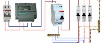
Let's consider a specific example: an electric oven and a washing machine are connected to a two-socket outlet at the same time. Both devices can require up to 4 kilowatts of power.
If the electrical system is protected by a standard 10 amp circuit breaker, then of course it will trip and open the circuit. The current strength of 10 amperes in terms of power (in a network with a rated voltage of 220V) will be 2.2 kW.
It is quite clear why in the described situation the machine worked, protecting the network from overload.
In a rash attempt to “overthink” the laws of physics, the user installs a more powerful 20-amp circuit breaker, which will allow two powerful consumers to be connected to the outlet at the same time, but in this case both the outlet and the wire feeding it will overheat and begin to smoke. The fact is that the socket and electrical wiring are also designed for the standard 10 amperes.
The meaning of the above example is that if there is a need to simultaneously turn on several powerful consumers, then you need to take care of replacing the electrical wiring with wires corresponding to the increased load cross-section, installing a socket that is more resistant to overloads, and using a suitable circuit breaker.
Ideally, such issues are resolved at the initial stages of building a house, or before major renovations. You should consider the layout of electrical appliances in your home and divide them into logical groups.
Provide for the installation of separate power branches for each of the groups, or individual wiring for particularly powerful consumers. It is necessary to calculate in advance the cross-section and length of the wires for each of the branches, purchase the required number of suitable sockets and circuit breakers.
Only in this way can you reliably and effectively protect electrical networks from overloads, electrical equipment from damage, and homes from fires.
What does it mean if the network is congested
Basically, we can say that an overloaded network receives too many requests and does not have the ability to resolve them all. This is what happens when there are a large number of devices connected to a cell tower, router, or access point.
Consider a multi-lane highway . Let's take the case when we are driving a car, and out of four lanes, one of them has almost no unsecured cars. We will be able to drive a car without problems, without stops and traffic jams. Suppose instead that the same four-lane highway has three completely occupied by trucks and buses. This forces cars into the fourth lane and has trouble moving at a good speed, causing constant traffic jams.
The last case - traffic jams - happens with an overloaded network. Everything we do on the Internet, such as sending email, opening a browser, playing streaming video... All of this will require transactions. Each transaction is divided into batches.
In order for all this to be properly separated, the TCP/IP system , which is the protocol that allows us to navigate the network just like we do. This is what establishes connections between computers and packets move from one site to another.
What to do if there are too many packages? We may have experienced the aforementioned network congestion. This can cause errors, slow performance, and even the inability to connect to the network.
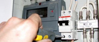
Wear and tear of electrical wiring
Old wires, twisted, bent, pinched many times and in many places, are the root cause of all problems.
In places of bends and pinches, the cross-section of the wire is reduced. Throughput is reduced. The insulating sheath of the wires dries out and cracks. A short circuit and associated overloads and wiring fires are just a matter of time.
So:
- Conduct timely inspection, repair and replacement of outdated electrical wiring;
- Do not skimp on high-quality electrical equipment and protection devices for electrical equipment and networks;
- Study the relevant technical literature, or better yet, use the services of professional electricians for periodic inspections and routine maintenance of your electrical networks and electrical equipment.
Protect your life and health, as well as the life and health of people living in your neighborhood from accidents and fires.
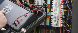
Methods for controlling heating of electrical equipment during operation
Methods for controlling heating of electrical equipment
To control the heating of electrical equipment, the following method is used:
- thermometer;
— resistance;
— thermocouples;
- infrared radiation.
control of heating of electrical equipment using the thermometer method
Thermometer method
used to measure the temperature of accessible surfaces. They use mercury (avoid, toxic!), alcohol and toluene glass thermometers, immersed in special sleeves hermetically built into the covers and casings of the equipment.
Mercury thermometers
have higher accuracy, but their use in conditions of electromagnetic fields is not recommended due to the high error introduced by additional heating of mercury by eddy currents.
If it is necessary to transmit a measuring signal over a distance of several meters (for example, from a heat exchanger in the transformer cover to a level of 2–3 m from the ground), manometric-type thermometers
, for example, thermal alarms TSM-10.
Thermal alarm TSM-10
consists of a thermal cylinder and a hollow tube connecting the cylinder to the spring of the indicating part of the device. The temperature detector is filled with liquid methyl and its vapors. When the temperature changes, the vapor pressure of methyl chloride changes, which is transferred to the needle of the device. The advantage of pressure gauge instruments lies in their vibration stability.
Monitoring heating of electrical equipment using a thermometer with a pressure gauge type indicator
The resistance method is based on taking into account the change in the resistance value of a metal conductor depending on its temperature. For powerful transformers and synchronous compensators, thermometers with a pressure gauge type indicator
. The connection diagram for the remote electric thermometer is shown in Fig. 22.
Rice.
22. Remote electric thermometer of manometric type
In a remote electric thermometer, the pointer arrows have two contacts for signaling the temperature set by the installation. When the contacts close, the corresponding relay in the alarm circuit is activated.
To measure temperature at individual points of synchronous compensators (in grooves for measuring steel, between the winding rods for measuring winding temperature and other points), thermistors
. The resistance of the resistors depends on the temperature at the measurement points.
Thermistors are made of platinum or copper wire, their resistances are calibrated.
The circuit for measuring temperatures using a thermistor is shown in Fig. 23.
Rice.
23. Circuit for measuring temperatures using a thermistor.
Such a thermistor R4 is connected to the arm of the resistive bridge. A power source is connected to one of the diagonals of the bridge, and a measuring device is connected to the other. Resistors R1-R4 in the bridge arms are selected in such a way that at the nominal temperature the bridge is in equilibrium and there is no current in the device circuit.
If the temperature deviates in any direction from the nominal value, the resistance of the thermistor R4 changes, the balance of the bridge is upset and the instrument needle deviates, showing the temperature of the measured point. Before measurement, the instrument needle must be in the zero position.
Monitoring heating of electrical equipment using resistance thermometers
Resistance thermometers are a means of remotely measuring the temperature of the windings and stator steel of generators, synchronous compensators, the temperature of cooling air, and hydrogen.
, which also use the dependence of the conductor resistance on temperature.
The designs of resistance thermometers are varied. In most cases, this is a thin copper wire bifilarly wound on a flat insulating frame, having an input resistance of 53 Ohms at a temperature of 0 ° C. As a measuring part
, working in conjunction with resistance thermometers, use automatic electronic bridges and ratio meters equipped with a temperature scale.
Resistance thermometers are installed in the stator of the machine during its manufacture at the factory. Copper resistance thermometers are placed between the winding rods and at the bottom of the groove.
Control of heating of electrical equipment using the thermocouple method
The thermocouple method is based on the use of the thermoelectric effect, i.e., the temperature dependence of the emf that occurs at the ends of an electrical circuit of dissimilar conductors, provided there is a difference in temperature between their junction point and the free ends of these conductors. Copper-constantan, chromel-copel, and platinum-rhodium thermocouples are most often used for measurements.
If the measured temperature does not exceed 100–120 °C, then there is a directly proportional relationship between the thermoEMF and the temperature difference between the heated and cold ends of the thermocouple.
Calibrated thermocouples are connected to compensation-type measuring instruments, DC potentiometers and automatic potentiometers, which are pre-calibrated. Using thermocouples, the temperatures of structural elements of turbogenerators, cooling gas, and active parts, for example, active stator steel, are measured.
Control of heating of electrical equipment using the infrared radiation method
The infrared radiation method is the basis for instruments that measure temperature by the intensity or spectrum of infrared radiation emitted by heated surfaces.
In the energy sector they are used as thermal imagers
(
thermal imagers)
and
radiation pyrometers
. Thermal imagers provide the ability to obtain a picture of the thermal field of the object under study and its temperature analysis. Using a radiation pyrometer, only the temperature of the test object is determined.
Very often, a thermal imager is used in conjunction with a pyrometer. First, using a thermal imager, objects with increased heating are identified, and then, using a pyrometer, their temperature is determined. Therefore, the accuracy of temperature measurement is determined, first of all, by the parameters of the pyrometer used.
Where to complain and how to compensate for damage
Initially, a complaint and a demand for compensation for damages is submitted to the company with which the contract is concluded. In this case, it is necessary to describe in detail what happened and why this particular company is considered to be at fault. Issues related to collective requests are resolved faster than individual requests. Therefore, in apartment buildings, it makes sense to cooperate with neighbors and submit one demand. The necessary contacts - addresses, telephone numbers, details - are indicated in the contract (often found in payment receipts).
Immediately after the incident, it is necessary to call electricians to record the fact of damage and draw up an appropriate report. Take burnt devices for examination - you should obtain written confirmation of the reason for the breakdown of the devices. Copies of the report and the expert’s opinion are attached to the written complaint to the energy company. If management refuses to compensate for losses, consumers can file a claim in court. You can draw up a competent claim yourself using the templates on the court’s website or with the help of a lawyer.
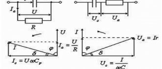
Overvoltage
Overvoltage becomes dangerous when its amplitude approaches the breakdown level of a semiconductor element (transistor or diode). Regarding IGBTs and MOSFETs, critical overvoltage can affect both the power (collector-emitter, drain-source) and signal terminals (gate-emitter, gate-drain). In Fig. Figure 2 shows the main types of overloads at the power terminals of semiconductor switches in the classic inverter rack circuit.
Rice. 2. Types of overvoltage
In any switching circuit, external and internal overvoltages may be present, having different origins. "External overload" can be considered as a dynamic increase in the switching voltage vK. This situation can be observed in a DC contact power supply network or in any DC power supply system. An increase in DC voltage is caused by various reasons; this occurs, for example, during dynamic braking of the electric drive or a failure in the pulse rectifier control algorithm.
“Internal overvoltage” is usually generated when the power switch operating on the inductive load LK (Dv = LK × di/dt) is turned off, or oscillations occur on the parasitic circuits of the switching circuits. Here are typical examples of such situations:
- Active switching off of load current iL by transistors S1 and S2 during normal operation of the inverter: in switching mode power supplies (SMPS), LK refers to the leakage inductance of the transformer, which is in the range of 1–100 nH.
- Reverse recovery (dirr/dt) when passively disabling fast diodes in hard switching (HS) or soft switching (ZCS) modes. Based on the principle of their operation, ZCS converters are characterized by a high inductance of the switching circuit, which can reach 10 μH.
- High short-circuit current shutdown speed (tens of kA/µs) in 2-level inverters with a DC link.
- Active emergency shutdown of DC bus current in current inverters (Current Source Inverter, CSI).
In addition to the above reasons, a power switch overload can be a consequence of static or dynamic imbalance when transistors are connected in series. Overvoltages during normal operation of converters or in emergency mode can be periodic (in the range of Hz and kHz) and aperiodic in nature.
Causes of overvoltages between signal terminals:
- driver power supply failure;
- feedback through the Miller capacitance due to a high dv/dt value (for example, in short-circuit mode);
- emitter/source feedback due to high di/dt switching speed;
- increase in gate voltage with active limitation;
- parasitic oscillations in the gate circuit (oscillatory process during switching of the power circuit, parasitic oscillations between gates of parallel switches, etc.).