What are dielectric losses?
The use of electrical insulating materials is based on the fact that they prevent electric current from traveling through a certain space limited by the insulator. An ideal insulator should absolutely exclude conditions for the conduction of electric current. Unfortunately, such materials do not exist in nature. Such dielectrics also could not be created in laboratory conditions.
Theoretically, it is possible to justify the existence of ideal insulators, but in practice it is not possible to synthesize such substances, since even a negligible fraction of impurities forms the dielectric constant. In other words, energy dissipation in a dielectric medium will always be observed. We can talk about efforts aimed at reducing such losses.
Based on the fact that part of the electricity is inevitably lost in the insulator, the term “dielectric losses” was introduced - the irreversible process of converting the energy of the electric field penetrating the dielectric medium into heat, that is, this is the electrical power aimed at heating the insulating material located in the action zone electric field.
The loss value is defined as the ratio of active power to reactive power. Typically, the active power consumed by a dielectric is very small compared to the reactive power. This means that the desired value will also be tiny - hundredths of a unit. For calculations, use the “tangent of the angle” value, expressed as a percentage.
The electrical characteristic expressing the dissipative property of the dielectric is called the dielectric loss tangent. In calculations, it is generally accepted that the dielectric is the insulating material of the capacitor, changing the capacitance and complementing the phase angle φ formed by the voltage and current vectors in the circuit up to 90º. This angle is denoted by the symbol δ and is called the dispersion angle, that is, dielectric loss. The value is numerically equal to the tangent of a given angle ( tgδ ), this is the very characteristic of dielectric heating.
tgδ is used in calculations to determine the amount of power dissipation using the appropriate formula. Therefore, its calculation is of practical importance. The introduction of the concept of tangent angle allows one to calculate the relative values of dielectric losses. And this allows you to compare the quality of different insulators.
It is this indicator or simply the angle δ that manufacturers of transformer oils indicate on the packaging of their products. The value of the angle (tg δ) can be used to judge the quality of the insulator: the smaller the angle δ, the higher the dielectric properties of the insulating material.
Calculation method
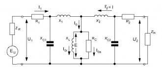
Let's make a circuit in which a capacitor and a dielectric are connected. In this case, the active power in this circuit must correspond to the power dissipated in the dielectric of the capacitor in question, and the shift angle formed by the current and voltage vectors must be equal to the shift angle in the capacitor. Such conditional circuits with serial and parallel connection of active resistance are presented in Fig. 1. Vector diagrams for each circuit are built on the same picture.
Rice. 1. Dielectric equivalent circuits
Rice. 2. Formulas for calculation
The meaning of the symbols is clear from Figure 1.
Note that in high-quality dielectrics the value of tan2 δ is very small, so it can be neglected. Then each of the formulas for calculating dielectric losses will take the form: Pa = U2*ω*C*tδ. If the voltage in this formula is expressed in volts, the angular frequency (ω) in s-1, and the capacitance C in farads, then we obtain the power (Pa) in watts.
It is obvious that the calculation parameters based on the above schemes depend on frequency. It follows from this that having calculated the parameters of dielectrics at one frequency, they cannot be automatically transferred for calculations in other frequency ranges.
Loss mechanisms manifest themselves differently in solid, liquid and gaseous substances. Let us consider the nature of scattering in these dielectrics.
Dielectric losses in different dielectrics
In gases
Gaseous substances or their inclusions in dielectric materials are characterized by ionization losses under certain conditions: when gas molecules are ionized. For example, ionization of gases occurs during electrical breakdowns by through current. In this case, gas molecules turn into ions, creating a conductive channel with a maximum voltage. As a result, dielectric losses increase like an avalanche, tending to the maximum tg angle.
With such dielectric losses, the power increases rapidly: Pi = A1 f (U – Ui)3, where A1 is a constant depending on the type of substance, f is the field frequency, and the symbols U, Ui indicate the applied voltage and ionization voltage, depending on the gas pressure.
If the voltage Ui does not reach the threshold required to trigger the impact ionization process, then the heating of the dielectric is insignificant, because, during polarization, the spatial orientation of dipole molecules in gases does not affect the electrical conductivity. Therefore, gases are the best dielectrics, with low losses, especially in the high frequency range.
The dependence of the tangent of the power dissipation angle in dielectrics with gas inclusions is illustrated by the graph in Fig. 3.
Rice. 3. Dependence of the loss tangent
In liquid dielectrics
The presence of dielectric losses in liquids mainly depends on their polarity. In a medium of non-polar dielectrics, scattering is caused by electrical conductivity. If there are impurities of dipole molecules in liquid substances (so-called polar liquids), power dissipation can be significant. This is due to an increase in electrical conductivity as a result of dipole-relaxation polarization.
Liquid polar insulators have a pronounced dependence of losses on viscosity. Rotating under the influence of a magnetic field in a viscous medium, the dipoles, as a result of friction, heat it up. The dissipated power of a liquid dielectric increases as long as the polarization mechanisms keep pace with changes in the electric field. When maximum polarization is reached, the process stabilizes.
In solids
High-frequency dielectrics with a non-polar structure have a small tan δ. These include quality materials:
- sulfur;
- polymers;
- paraffin and some others.
Losses for dielectrics with a polar molecule are more significant. Such materials include:
- organic glass;
- ebonite and other rubber substances;
- polyamides;
- cellulose-containing materials;
- phenol-formaldehyde resins.
Ceramic dielectrics without impurities have a dense ion-lattice structure. They have high resistivity. and the tan δ value of such materials does not exceed 10-3.
Substances with a loose arrangement of ions have ionic polarization. They also exhibit electron polarization. tan δ of these dielectrics is even higher – from 10-2.
Ferroelectrics and substances with complex inhomogeneous structures, such as textolite, plastics, getinax and others, have tan δ > 0.1.
Power dissipation due to through conduction occurs in all dielectrics. However, losses become noticeable only at frequencies from 50 to 1000 Hz, at temperatures above 100 ºC. High alternating voltage, like resistivity, also affects the amount of dissipation.
Digital library
General engineering disciplines / Materials science, technology of structural materials / 9.2.3 Dielectric losses
General definitions
Dielectric losses
is the energy dissipated per unit time in a dielectric when exposed to an electric field and causing heating of the dielectric.
If a dielectric is exposed to an alternating electric field of intensity E
and circular frequency
ω
, then two types of electric currents arise in it: displacement current or capacitive current and conduction current (Fig. 9.10).
The bias current density is:
. (9.11)
The conduction current density is determined as follows:
, (9.11)
where is the specific active conductivity of the dielectric at the angular frequency ω
.
Total current density ( J
) is equal to the vector sum of the displacement and conductivity current densities (Fig. 9.9). If the dielectric were ideal, i.e. without losses (), the current would be purely reactive and its density:
(see Fig. 9.10) would be directed along the imaginary axis at an angle of 90° to the vector. However, for real dielectrics, with , different from zero, the total current is shifted by an angle relative to the current of the ideal dielectric ( φ
– phase shift angle between current and voltage).
The larger , the greater the angle δ
, which characterizes the degree of difference between the real dielectric and the ideal one.
Rice. 9.10. Vector diagram (complex plane) of current density in a dielectric
Angle δ
between the density vectors of the alternating current of the dielectric and the displacement current on the complex plane is called
the dielectric loss angle
. Tangent of this angle
(9.12)
is one of the most important parameters not only of dielectrics, but also of capacitors, insulators and other electrical insulating elements. Or in other words, the dielectric loss angle ( δ
) is called an angle that complements up to 90° the phase angle (
φ
) between current and voltage in a capacitive circuit.
Power dissipated per unit volume of a substance, i.e. so-called specific dielectric losses
, are equal:
or
, (9.13)
where E
– effective value of the alternating field strength, V/m.
The higher tan δ
, the greater the heating of the dielectric in an electric field of a given frequency and strength.
The introduction of the dimensionless parameter tan δ
is convenient because it does not depend on the shape and size of the insulation section, but is determined only by the properties of the dielectric material.
If a voltage with angular frequency ( ω
) and the effective value of
U
, then the ratio of the passing conduction current
(where Ra
– active resistance of the element at frequency ) and displacement current
(where C
– capacity) can be expressed as follows:
.
Since , a , where is the geometric size, then
. (9.14)
Total dielectric losses in the insulation section with capacitance C
when applying voltage
U
(rms value) with angular frequency
ω
are equal to:
. (9.15)
Along with losses tg δ
characterizes the quality factor of the capacitor (
Q
), and therefore the maximum possible quality factor of the circuit with a given capacitor:
. (9.16)
Thus, tan δ
is the reciprocal of the quality factor.
High dielectric losses lead to heating and thermal breakdown of dielectrics in strong electric fields, reducing the quality factor and selectivity of oscillatory circuits. In this regard, they strive to reduce tan δ
dielectric materials, which is possible if the nature of dielectric losses is known.
Types of dielectric losses
Dielectric losses, according to their characteristics and physical nature, can be divided into five main types:
1) due to through electrical conductivity;
2) caused by relaxation (slow) types of polarization;
3) due to the heterogeneity of the structure (migration);
4) ionization;
5) resonant.
Dielectric losses due to through conductivity
manifest themselves in all dielectrics without exception, both in constant and alternating electric fields.
Part of the dielectric losses caused by the through current of the dielectric is called dielectric losses due to electrical conductivity
.
Electrical conductivity losses are negligible for electrical insulating materials with high resistivity (polyethylene, polytetrafluoroethylene, etc.), and at high and ultra-high frequencies - for almost all materials. However, they must be taken into account in insulation operating at elevated temperatures (above 100 ° C), as well as under humidification and other conditions leading to a decrease in resistivity.
Dielectric losses due to relaxation (slow) types of polarization
can manifest themselves in polar dielectrics and only in alternating electric fields.
The active conductivity of dielectrics () at alternating current is usually significantly greater than the conductivity () at direct current. The loss tangent, even at high frequencies, does not fall below 10-4. Consequently, there are other mechanisms of dielectric losses, in addition to losses due to through conduction current. These mechanisms are associated with the polarization of the dielectric.
Dielectric losses due to polarization will be maximum when the period of change in the electric field is comparable to the time of establishment of polarization ( τ
).
If the field frequency is , the polarization does not have time to follow the field changes, the polarization and dielectric constant will become lower than low-frequency ones. In the frequency range, there is a change in dielectric constant with increasing frequency, called dielectric dispersion
.
Dielectric dispersion can be relaxational (ε monotonically decreases with increasing ω
) or resonant (
ε
goes through a maximum and a minimum with increasing frequency) character.
ε values
and tan
δ
of polar dielectrics strongly depend on temperature (
T
).
At high temperatures, a decrease in ε
with increasing
T
is associated with the disorienting effect on the dipole polarization of chaotic thermal motion, resulting in .
At low temperatures ε
drops to ε because the relaxation frequency becomes lower than the measurement frequency.
The higher the measurement frequency, the higher the drop temperature ε
(
T
).
At temperatures of falling ε
(
T
), relaxation maxima of losses are observed. Thus, relaxation dispersion can be observed when not only the frequency but also the temperature changes.
In polar dielectrics, the observed losses are the sum of conduction losses and relaxation losses. Dielectric losses caused by structural inhomogeneity are typical for composite dielectrics, as well as for dielectrics with various (including conductive) impurities.
Migration polarization is caused by the migration of charges in conductive inclusions and their accumulation at the boundaries of inhomogeneities. The process of migration polarization is established very slowly and does not have time to follow the change in the magnitude and direction of the high-frequency electric field. Therefore, migration polarization decreases with increasing frequency; migration losses are observed at low frequencies and in the frequency range of its dispersion.
Ionization losses
, or partial discharge losses, are observed in porous dielectrics when the voltage increases above a certain limit (), called
the ionization threshold
(Fig. 9.11).
At higher voltages, partial discharges appear in air inclusions or other defects inside the dielectric, leading to dissipation of the electric field energy. Dielectric losses caused by the ionization of a dielectric in an electric field are called ionization dielectric losses
.
Rice. 9.11. Ionization losses of porous dielectrics at voltages higher than the ionization voltage ( U ion
)
When exposed to partial discharges, the dielectric can gradually collapse. Therefore, the operating voltage should be chosen below the ionization voltage () corresponding to the beginning of the increase in tg δ
.
tan δ
on voltage (Fig. 9.11) is called
ionization curve
.
The quality of high voltage electrical insulation is assessed using the ionization curve: the smaller the increment in tg δ
δ
begins at higher voltages , the better the insulation. To improve the quality of high voltage electrical insulation, it is impregnated, filling the pores with oils, varnishes, compounds, and high-pressure gases.
Resonant dielectric losses
occur during dispersion of a resonant nature, when the frequency of the electric field approaches the natural frequencies of electrons or ions.
Resonant losses of electronic polarization have maximums in the optical range: infrared, visible and ultraviolet regions of the spectrum (at frequencies 1014...1017 Hz). They are associated with the absorption of light by a substance. The losses are accompanied by the frequency dependence of the refractive index and are maximum in the region of the so-called “anomalous” dispersion, where ε
decreases with increasing
ω
(by “normal” dispersion in optics they mean an increase in the refractive index with increasing frequency).
The maximum resonant losses of ion polarization are observed in the infrared range at frequencies of 1013...1014 Hz. However, in substances with high dielectric constant, as well as in glasses and glass ceramics, where there are weakly bound ions, ion resonance frequencies can be lower (~1012 Hz). In this case, the beginning of the resonant loss maximum covers the microwave range (109...1010 Hz).
Dielectric losses in gases
Dielectric losses in gases at electric field strengths below the value required for the development of impact ionization are very small. In this case, the gas can be considered as an ideal dielectric. The source of dielectric losses in this case is mainly through electrical conductivity. Since gases have very low electrical conductivity, the dielectric loss angle will therefore be negligible, especially at high frequencies
At high electric field strengths, as well as in non-uniform electric fields, when the strength of some areas exceeds a certain critical value, gas molecules are ionized, as a result of which ionization losses occur in the gas.
Dielectric losses in liquid dielectrics
In non-polar liquid dielectrics
dielectric losses are due only to through electrical conductivity if the liquid does not contain impurities with dipole molecules, and the value of tg
δ
will increase with increasing temperature, and will decrease with increasing frequency of the applied electric field.
In polar liquids
, depending on operating conditions, temperature rise, frequency, etc.
Losses due to dipole-relaxation polarization may appear, in addition to losses due to electrical conductivity. For such liquids, the dependences of tan δ
on temperature and frequency of the applied electric field are more complex.
Dielectric losses in solid dielectrics
Dielectric losses in solid dielectrics must be considered in connection with their structure. Solid dielectrics have different properties and structures; all types of dielectric losses can exist in them.
In non-polar solid dielectrics
, which do not have impurities, dielectric losses are determined by through electrical conductivity, and the value of tan
δ
will increase with increasing temperature, and decrease with increasing frequency of the applied electric field.
In polar solid dielectrics
having dipole-relaxation, ion-relaxation and other slow types of polarization, depending on operating conditions (elevated temperatures, frequencies, etc.), noticeable losses associated with slow types of polarization may occur.
Dielectric losses in solid dielectrics of inhomogeneous structure
Such dielectrics include materials that contain at least two components that have not entered into a chemical reaction, i.e. mechanically mixed with each other. Inhomogeneous dielectrics include: ceramics, laminated plastics, impregnated paper, cardboard, fabrics, etc. The dielectric losses of such materials are determined by the properties and quantitative ratio of the components, therefore the dependences tg δ
on the temperature and frequency of the applied electric field are very complex.
Rice. 9.12. Dependence tan δ
on temperature for condenser paper impregnated with compound (80% rosin + 20%
For example, the dependence curve tan δ
on temperature (Fig. 9.12) for paper impregnated with an oil-rosin compound has two maxima: the first (at low temperatures) characterizes the dielectric losses of the paper (cellulose) itself; the second (at a higher temperature) is due to dipole-relaxation losses of the impregnating compound.
Types of dielectric losses
Depending on the electrical properties of various types of dielectrics, the following types of dielectric losses are distinguished, accompanied by heating of the dielectric:
- ionization losses observed in gases;
- relaxation losses in liquid (viscous) dielectrics as a result of relaxation polarization;
- scattering in substances with dipole polarization;
- polarization scattering in substances with through electrical conductivity;
- high frequency resonant losses;
- dielectric losses caused by the inhomogeneity of the structure of solid dielectrics.
Dielectric substances behave differently at different temperatures, with direct or alternating current. Maximum losses occur when a certain temperature threshold is reached. This threshold is individual for each substance. The tangent of the angle δ also depends on the applied voltage (Fig. 4).
Rice. 4. Dependence of tangent on voltage
In liquid
The loss values will depend on the composition of the materials. A liquid without impurities will be neutral, and accordingly, losses in it will be almost zero. This is due to low electrical conductivity.
If there is impurity or polarity in the liquid, it will be used in technical circuits, since their dielectric losses are much higher. Such liquids have distinctive features, one of which is the viscosity of the substance.
Sometimes such liquids are called dipole due to the installation of dipole polarization. The higher the viscosity, the higher the dielectric losses will become.
In liquid dielectrics, temperature has a certain significance. If you increase the temperature with the help, the tangent in the coal will also increase, and to maximum values.
In the same way, you can lower it to a minimum and increase it again. This depends on electrical conductivity, which changes under the influence of temperatures.
How to measure?
It is not very convenient to calculate dielectric losses using the formula. Manufacturers often determine the tg value empirically and indicate it on packaging or in reference books.
There are special measuring instruments, such as “IPI-10” (or the “Sh2” meter), which allow you to accurately determine the level of dissipation in dielectrics or find the tangent of the dispersion angle. The devices are quite compact and easy to use. With their help, you can study the properties of solids and liquid substances for dielectric losses.
What instruments can be used to measure
Losses can be measured using various instruments. For example, IPI-10 from the manufacturer Tettex, which allows you to study solid and liquid dielectric materials.
Sometimes devices are used to measure tangents of angles in liquid-type dielectrics, for example, Tangent-ZM. Sh2-12TM meters are also actively used to identify the required values.
These are the main points you should know about dielectric losses. Thanks to the formulas from the article, you can calculate losses for different materials!
