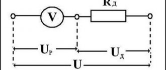
If, when repairing an air conditioner, you find a blown fuse on the circuit board, do not rush to change it immediately; first find out the reason why it burned out.
Most likely this happened due to power surges in the network.
When measuring the supply voltage in the network, it constantly fluctuates, and not always within safe limits for air conditioners.
Plus, the network always contains short pulses with voltages of several kilovolts. This happens due to the constant switching off and on of inductive and capacitive loads (electric motors, transformers, etc.), as well as due to atmospheric electricity.
Air conditioners, like any other electronic equipment, are protected in this case by varistors. More precisely, the electronic filling of the air conditioner - the control board.
Causes of malfunction
Varistors are installed in parallel with the protected circuit, and a fuse is placed in series with it. This is necessary so that when the varistor burns out, if the overvoltage pulse is too strong, the fuse will burn out, and not the tracks of the printed circuit board.
The only reason for the failure of a varistor is a sudden and strong voltage surge in the network. If the energy of this jump is greater than the varistor can dissipate, it will fail. The maximum energy dissipation depends on the dimensions of the component. They differ in diameter and thickness, that is, the larger they are, the more energy the varistor can dissipate.
Voltage surges can occur during accidents on power lines, during a thunderstorm, or when switching powerful devices, especially inductive loads.
Advantages and disadvantages
To use a varistor, you should become familiar with its positive and negative sides, since the protection of electronics depends on this. The positive qualities include the following:
- High response time.
- Tracking differences using the inertia-free method.
- Wide voltage range: from 12 V to 1.8 kV.
- Long service life.
- Low cost.
A varistor, in addition to its advantages, has serious disadvantages that should be taken into account when developing any device . These include:
- Large capacity.
- Do not dissipate power at maximum voltage.
The capacitance of a semiconductor device ranges from 70 to 3200 pF and therefore significantly affects the performance of the circuit. This value depends on the design and type of device, as well as on the voltage. However, in some cases this disadvantage is an advantage when using it in filters. The value of the larger capacitance limits the voltage value.
At maximum voltage values, varistors-dischargers should be used to dissipate power, since an ordinary semiconductor device will overheat and fail. Every radio amateur should know the algorithm for checking a varistor, since when contacting service centers there is a possibility of paying more for repairs than it actually costs.
Verification methods
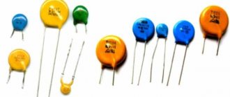
Any repair of electronics and electrical equipment begins with an external inspection, and then proceeds to measurements. This approach allows you to localize most faults. To find a varistor on the board, look at the figure below - this is what varistors look like. Sometimes they can be confused with capacitors, but can be distinguished by their markings.
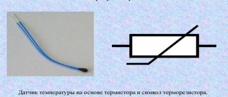
If the element is burnt out and the markings cannot be read, look at this information on the device diagram. On the board and in the diagram it can be designated by the letters RU. The conventional graphic symbol looks like this.
There are three ways to test a varistor quickly and easily:
- Visual inspection.
- Call. This can be done with a multimeter or any other device that has a continuity test function.
- Resistance measurement. This can be done with a high-range ohmmeter, multimeter or megger.
A varistor fails when a large or prolonged current passes through it. Then the energy is dissipated in the form of heat, and if its amount is greater than that determined by the design, the element burns out. The housing of these components is made of a hard dielectric material, such as ceramic or epoxy coating. Therefore, when it fails, the integrity of the outer coating is most often damaged.
You can visually check the varistor for functionality - there should be no cracks on it, as in the photo:
The next method is to check the varistor with a tester in continuity mode. This cannot be done in the circuit, because the dialing can work through parallel-connected elements. Therefore, you need to unsolder at least one of its legs from the board.
Important: you should not check the elements for serviceability without desoldering them from the board - this may give false readings from the measuring instruments.
Since in the normal state (without voltage applied to the terminals) the resistance of the varistor is high, it should not ring through. The test is performed in both directions, that is, by swapping the multimeter probes twice.
On most multimeters, the continuity mode is combined with the diode testing mode. It can be found by the diode icon on the mode selector scale. If there is a sound indication sign next to it, it probably also has a dial tone.
Another way to test a varistor for breakdown with a multimeter is to measure the resistance. You need to set the device to the maximum measurement limit, in most devices this is 2 MOhms (megaohms, designated as 2M or 2000K). The resistance must be equal to infinity. In practice, it can be lower, within 1-2 MOhm.
Interesting! The same can be done with a megaohmmeter, but not everyone has one. It is worth noting that the voltage at the megohmmeter terminals should not exceed the classification voltage of the component being tested.
This ends the available methods for checking a varistor. This time, the multimeter will help the radio amateur find the faulty element, as in a large number of other cases. Although in practice a multimeter is not always needed in this matter, because the matter rarely goes beyond a visual inspection. Replace the burnt element with a new one, designed for voltage and with a diameter no less than the burnt one, otherwise it will burn out even faster than the previous one.
Source: samelectrik.ru
Operating principle of a varistor
Varistor protection is connected in parallel to the main equipment that needs to be protected. After a voltage pulse occurs, due to the presence of a nonlinear characteristic, the varistor shunts the load and reduces the resistance value to several fractions of an ohm. Energy, when overvolted, is absorbed and dissipated as heat. The varistor, as it were, cuts off the dangerous overvoltage pulse, so the protected device remains unharmed, which is possible even with a low level of insulation.
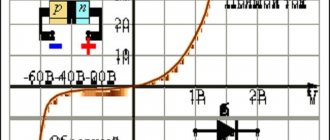
Rice. No. 1. Design diagram of a varistor and its characteristics.
Symbol of a varistor, for example, СНI-1-1-1500. CH means nonlinear resistance, the first digital value is the material, the second is the design (1-rod; 2 - disk), the third digit is the design number, the last digit indicates the voltage drop value.
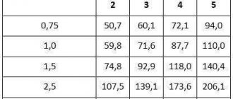
Varistor classification table
How to check a varistor with a multimeter
A varistor is a kind of semiconductor resistor that has a nonlinear current-voltage characteristic. That is, until the electrical voltage at its contacts has reached a certain threshold value, it will not pass current (or rather, it will, but it will be negligibly small compared to the currents flowing in the circuit where it is installed). If this level is exceeded, the varistor will open (its resistance from several million Ohms will drop to units and fractions of Ohms).
Since no other accompanying currents arise when the varistor switches, it is used as a surge protection device.
It acts as a shunt, closing on itself all the excess energy from voltage exceeding the threshold. Varistors are made from silicon carbide or zinc oxide. The nonlinearity of the characteristics of the latter is higher.
Low-voltage varistors operate in the range from 3 to 200 V, and high-voltage varistors can be used at voltages up to 20,000 V.
When threshold voltages are exceeded, currents of thousands and tens of thousands of amperes flow through the varistor, but due to the short pulse duration (from several nanoseconds to tens of microseconds), the released thermal energy has time to dissipate and the device remains in working condition.
In power devices there is a fuse in series with it. The surge voltage is absorbed by the varistor, and with prolonged overvoltage, the fuse blows.
Varistor marking
There are a huge number of varistors from different manufacturers, with different threshold operating voltages and designed for different currents. You can find out which varistor was installed by its marking. For example, marking varistors CNR :
CNR-07D390K , where:
- CNR-series, full name CeNtRa metal oxide varistors
- 07- diameter 7mm
- D – disk
- 390 – actuation voltage, calculated by multiplying the first two digits by 10 to the power equal to the third digit, that is, 39 multiplied by 10 to the zero power, you get 39 V, 271-270 V, etc.
- K – tolerance 10%, that is, the voltage spread can fluctuate from the nominal by 10% in any direction.
Functional check
When devices malfunction, the state of the power circuits is first determined, and the task arises of how to check the varistor. First, an external examination is done.
Check for carbon deposits, blackening or mechanical damage. If any of this is present, the varistor needs to be replaced. Otherwise, unsolder at least one pin.
Without soldering the contacts, it will not be possible to measure the resistance of the varistor, since it is connected in parallel to the entire circuit of the device or some of its modules. Therefore, instead of determining the resistance of the varistor, at best, the total resistance of the entire device will be measured.
To desolder the lead, you need a soldering iron, desoldering pump, and pliers. The area around the terminal is heated with a soldering iron. The molten solder is pumped out using a desoldering pump. Use pliers to remove the varistor lead from the board.
Then a direct test of the varistor begins with a multimeter or ohmmeter. The operating mode switch is set to the “resistance measurement” position. The largest measurement scale (200 MΩ) is selected.
The probes are connected to the varistor terminals. Resistance is measured. Then the probes are swapped and the second value of the measured resistance is recorded.
The multimeter should show values in the tens of megohms. If in at least one measurement the multimeter shows values other than MOhm, it means that the varistor is faulty and needs to be replaced.
Some devices have a fuse in series with the varistor. Then just take it out and we get a version with one free contact. There is no need to solder anything.
Next, you should use a multimeter, and how the varistor is checked and measurements are taken was described above.
Application of a rheostat
Over time, the varistor parameters change. Its response threshold may shift, which will lead to failure of the entire device.
To check the actual threshold voltage, in addition to a multimeter, you will need an LATR or a rheostat connected according to a potentiometer circuit, a fuse in a glass or ceramic case of 0.5-1 Ampere.
To do this, a circuit is assembled in which an electric potential exceeding the varistor response voltage is supplied to the rheostat. One terminal of the varistor is connected to the middle moving contact of the rheostat, and a fuse is connected to the second. The other contact of the fuse is connected to one of the extreme contacts of the rheostat.
The multimeter is connected in parallel to the varistor and switched to voltmeter mode. The switch selects a scale that covers the value of the input voltage of the assembled circuit.
Then, using the moving contact of the rheostat, the voltage smoothly changes from zero until the varistor operates. This is determined by a voltmeter. At first, the multimeter readings will increase, and then reset to zero.
The last maximum non-zero value will be the threshold voltage.
Application in analog technology
If a varistor in a circuit is used as an analog computer, then do not limit yourself to just measuring resistance by transferring test leads from one contact to another.
The use of a varistor in an analog computer for exponentiation, root extraction and other mathematical operations requires a certain accuracy in setting the parameters. In this case, it will be necessary to construct a current-voltage characteristic to verify the correctness of the calculations.
As in the previous case, you will need a rheostat, a fuse and two multimeters. First, according to the first scheme, the varistor is checked for serviceability.
Then the second multimeter is connected in series to the varistor in milliammeter mode. Now, using a rheostat, the voltage on the varistor changes from 0 to a value that does not reach the threshold.
Multimeter readings are recorded with such a voltage change step that it is possible to draw a high-quality current-voltage characteristic from them. Depending on the resulting parabola, other nonlinear elements will be added to correct it or the varistor will be replaced.
Source: evosnab.ru
Checking the varistor with a multimeter, determining its performance
Each radio component in the electrical circuit has its own purpose. Some change parameters, others are status indicators or command executors.
There are radioelements responsible for safety and protection (we are not talking about banal fuses). For example, a varistor, which sharply changes its characteristics during voltage surges.
This property is used in protection systems for power supplies and switching devices. In addition, it is used as a simple pulse voltage filter. The part is inexpensive, but quite effective.
If your extension cord or electrical appliance does not perform its function after a power surge, do not rush into delving into the circuit design. Sometimes it is enough to know how to test a varistor with a multimeter.
What is this element and how does it work?
Varistors are a type of resistors made of semiconductor.
Designation on the diagram
The peculiarity of this element is an abrupt change in resistance at certain voltage values. That is, up to a given value, the resistance of the varistor is kept in a stable state. After exceeding the voltage, the resistance rapidly decreases and tends to zero.
As can be seen in the volt-ampere characteristic graph, the current flowing through the varistor is stable over a given voltage range. As it increases, the current increases sharply. This happens precisely because of the avalanche-like decrease in resistance.
To know how to check a varistor for serviceability with a multimeter, consider its design.
The ceramic layer contains zinc oxide crystals. Depending on their concentration, when a certain voltage is reached at the connecting terminals, the resistance of the ceramic layer and the current flowing through it change.
How a viristor works, a clear example - video
Of course, there is a so-called survivability threshold: the magnitude of the current multiplied by the transit time. When a critical value is reached, the part is thermally destroyed and the circuit will be open . The performance of the varistor depends on this value: that is, the ability to withstand voltage surges.
For example, varistor K275: It can operate in circuits up to 450 volts, and is triggered when the voltage reaches 275 volts. The ability to absorb energy of 151 J allows it to take on a current of 8000 amperes within a few milliseconds. Then the part fails.
Marking and main parameters
The marking of varistors is different, since each manufacturer of these radio components has the right to install it independently. This is primarily due to its technical characteristics. For example, differences in voltages and required current levels for its operation.
Among domestic ones, the most common is K275, and among imported ones - 7n471k, 14d471k, kl472m and ac472m. The most popular is a varistor, the marking of which is CNR (there are also hel, vdr, jvr). In addition, the alphanumeric index 14d471k is attached to it, and this type of designation is deciphered as follows:
- CNR - metal oxide type.
- 14 - device diameter equal to 14 mm.
- D is a disc-shaped radio component.
- 471 is the maximum voltage value for which it is designed.
- K is the permissible deviation of the classification voltage equal to 10%.
There are technical specifications required for application in the circuit. This is because different types of semiconductor resistance must be used to protect different circuit elements.
Their main characteristics:
- Classification voltage is the value of the potential difference, taken into account that a current of 1 mA flows through the varistor.
- The maximum value of the alternating voltage is the rms value at which it opens and, therefore, the value of its resistance decreases.
- The constant maximum voltage value at which the varistor opens in a DC circuit. As a rule, it is greater than the previous parameter for a current of variable amplitude.
- The permissible voltage (limitation voltage) is the value above which the element fails. Indicated for a specific current value.
- The maximum energy absorbed is measured in J (joules). This characteristic shows the amount of pulse energy that a varistor can dissipate and not fail.
- Response time (unit - nanoseconds, ns) - the value required to transition from one state to another, that is, a change in resistance value from a high value to a low value.
- Classification voltage error is a deviation from its nominal value in both directions, which is indicated in % (for imported models: K = 10%, L = 15%, M = 20% and P = 25%).
After describing the operating principle, marking features and main characteristics, the scope of application of varistors should be considered.
The use of varistors in protection circuits
Based on the properties of the element, it is logical to use it in bypass circuits of the main electrical circuit. When the supply voltage increases, the varistor will act as a kind of shunt.
During a pulsed (several milliseconds) voltage surge, the main current will bypass the circuit. When the parameters are restored, the power supply to the circuit will instantly resume.
However, there is a risk of a prolonged increase in voltage; the protection will not work. Therefore, a disconnecting device is installed in the power circuit with a varistor: a fuse or a circuit breaker.
The simplest example is that a varistor is connected parallel to the power supply in an extension cord with protection. When there is a voltage surge, the element actually forms a short circuit and the circuit breaker is triggered.
Most often, varistors of the TVR 14561 type are used in such circuits.
How to check the performance of a varistor?
We already know that a varistor is essentially a resistance. Therefore, it can be checked with a tester. The simplest way is to measure resistance. It is necessary to remove the part from the circuit and check the resistance in different measurement ranges.
The resistance should be infinitely high - this indicates the serviceability of the varistor. If the circuit does not have additional resistance in the connection circuit, you can check the varistor with a multimeter without desoldering.
For example, in the same extension cord. Just remember to unplug the plug from the socket and turn off all consumers connected to the extension cord.
If it is necessary to accurately measure parameters, it is necessary to assemble a circuit from a not too demanding consumer (for example, a powerful incandescent lamp) and a fuse.
By load we mean the same lamp.
How to check S14 K275 using this method?
We know that the trigger voltage is 275 volts. When a voltage of 220 volts is supplied, the circuit operates in operating mode: the varistor has infinite resistance, current flows through the main circuit, and the lamp lights up.
We apply increased voltage to the input (for example, 400 volts). The varistor goes into protection mode (the resistance drops sharply, current flows through it), the fuse blows, and the lamp goes out. Conclusion: the varistor is working.
Overview of varistors
The Littelfuse company produces a wide range of varistors (Figure 9). They can be divided into five segments (Table 4):
- MOV and MLV varistors for surface mounting ( SMD );
- MOV varistors with radial leads;
- industrial MOV varistors with high dissipation energy;
- specialized varistors;
- MOV varistors with additional thermal protection.
Rice. 9. Littelfuse varistors
Table 4. Overview of Littelfuse varistors
| Name | Operating voltage range AC, V | Operating voltage range DC, V | Peak current range, A | Peak energy range, J | Operating temperature range, °C | Number of protected lines | Execution | Disc size, mm |
| SMD MOV and MLV | ||||||||
| M.H.S. | – | 9…42 | – | – | -55…125 | 1 | SMD | – |
| MLE | – | 18 | – | – | ||||
| 0201 MLA | – | 5,5 | – | – | ||||
| M.L.A. | 2,5…107 | 3,5…120 | 4…500 | 0,02…2,5 | ||||
| MLA Automotive | 2,5…40 | 3,5…48 | 500 | 0,1…2,5 | ||||
| AUML | 18…48 | 1,5…25 | ||||||
| MLN | 4…14 | 5,5…18 | 30 | 0,05…0,10 | 4 | |||
| CH | 14…275 | 18…369 | 100..400 | 1,0…8,0 | 1 | |||
| SM7 | 50…510 | 68…675 | 1200 | 10…40 | -55…85 | |||
| SM20 | 20…320 | 26…420 | 6500 | 165 | ||||
| MOV varistors with radial leads | ||||||||
| LV UltraMOV | 11…95 | 14…127 | 500…10000 | 0,8…150 | -55…85 | 1 | Radial leads | 5, 7, 10, 14, 20 |
| UltraMOV | 130…625 | 170…825 | 1750…10000 | 12,5…400 | 7, 10, 14, 20 | |||
| UltraMOV® 25S | 115…750 | 150…970 | 22000 | 230…890 | 25 | |||
| C-III | 130…1000 | 3500…10000 | 40…530 | 10, 14, 20 | ||||
| L.A. | 130…1000 | 175…1200 | 1200…6500 | 11…360 | 7, 10, 14, 20 | |||
| ZA | 4…460 | 5,5…615 | 50…6500 | 0,1…52 | 5, 7, 10, 14, 20 | |||
| AUMOV | 14…42 | 16…50 | 400…5000 | 1,0…140 | -40…125 | 5, 7, 10, 14, 20 | ||
| HMOV | 11…625 | 14…825 | – | 4,2…490 | 10, 14, 20 | |||
| Industrial MOV Varistors with High Dissipation Energy | ||||||||
| BA/BB | 130…2800 | 175…3500 | 50000…70000 | 450…10000 | -55…85 | 1 | Screw or snap terminals | 60 |
| DA/DB | 130…750 | 175…970 | 40000 | 270…1050 | 40 | |||
| H.A. | 110…750 | 148…970 | 25000…40000 | 160…1050 | Radial leads | 32, 40 | ||
| HB34, HF34, HG34 | 110…750 | 148…970 | 40000 | 220…1050 | 34 | |||
| DHB34 | 110…750 | 148…970 | 40000 | 220…1050 | 34 | |||
| C.A. | 250…2800 | 330…3500 | 20000…70000 | 880…10000 | Leadless drive | 60 | ||
| Specialized MOV varistors | ||||||||
| M.A. | 9…264 | 13…365 | 40…100 | 0,06…1,7 | -55…85 | 1 | Axial leads | – |
| R.A. | 4…275 | 5,5…369 | 100…6500 | 0,4…160 | -55…125 | Radial leads | – | |
| High Reliability | 130…320 | 175…420 | 6000 | 50…120 | -55…85 | various | 7, 10, 14, 20 | |
| MOV varistors with thermal protection | ||||||||
| TMOV/iTMOV | 115…750 | 150…970 | 6000…10000 | 35…480 | -55…85 | 1 | Radial leads | 14, 20 |
| TMOV®25S | 115…750 | 150…970 | 20000 | 170…670 | 25 | |||
| TMOV®34S | 115…750 | 150…970 | 40000 | 280…1200 | 34 | |||
| SMOV®25S | 115…750 | 150…970 | 20000 | 170…670 | -45…75 | 25 | ||
| SMOV®34S | 115…750 | 150…970 | 40000 | 280…1200 | 34 | |||
| FBMOV | 115…750 | 150…970 | 40000 | 340…1340 | -55…85 | Bolted terminals | – | |
Surface Mount Varistors (SMD)
Traditional lead-out varistors cannot always be used in compact applications due to lack of available space. In addition, electronics manufacturers are trying to move away from pin-out mounting and use surface mounting as much as possible where possible. SMD varistors help solve this problem. Most SMD varistors use a multilayer MLV design, but the Littelfuse range also includes single-layer SMD varistors. SMD varistors produced by Littelfuse cover a wide range of operating voltages from units to hundreds of V and are capable of withstanding peak currents of up to several thousand A. Let's consider some lines from this segment (Figure 10).
Rice. 10. Examples of Littelfuse SMD varistors
MLA series – miniature multilayer SMD varistors for protecting DC and AC voltage circuits. Currently, the series includes more than fifty models with various standard sizes 0402/0603/0805/1206/1210, with an operating voltage range of 2.5...107 V AC and 3.5...120 V DC. The range of peak currents for representatives of the series turns out to be quite wide: 4...500 A (pulse 8/20 μs). MLA varistors are capable of operating in a wide range of operating temperatures -55...125°C.
MLA Automotive series is an analogue of MLA varistors for automotive applications. This series has AEQ-Q200 certification and unites about forty representatives with operating voltages of 2.5...107 V AC and 3.5...120 V DC. Models with standard sizes 0603/0805/1206/1210 are available to developers. The operating temperature range for these varistors is also -55...125°C. In addition to AEQ-Q200 qualification, MLA Automotive varistors are capable of withstanding high-power surges during load shedding, in accordance with SAE J1113 requirements.
AUML series is another series of MLV varistors for automotive applications that are AEQ-Q200 qualified. Unlike the series discussed above, AUML varistors have only five operating voltage options: 16, 18, 24, 48, 68 V. Among the advantages of varistors of this series, it is worth noting the compact standard sizes 1206/1210/1812/2220 and resistance to powerful impulse noise . In particular, AUML varistors are capable of withstanding more than 10 pulses, in accordance with SAE J1113.
CH series – compact MOV varistors for protecting AC and DC voltage circuits (Figure 9). These varistors are an excellent alternative to traditional radial lead varistors in applications with tight space constraints. The series includes a dozen and a half models with operating voltages 14...275 V AC and 18...369 V DC, peak current up to 600 A and miniature dimensions of only 5x8 mm. It is also worth noting the wide range of operating temperatures -55...125°C.
SM7 series is the highest voltage series of Littelfuse SMD varistors. Representatives of the series cover the operating voltage range of 50…510 V AC and 68…675 V DC. SM7 varistors have a plastic housing with dimensions of 11.4x8.3 mm. The case height is 3.6 mm or 6.0 mm depending on the model. The peak current for SM7 varistors reaches 1200 A (pulse 8/20 μs), and the operating temperature range is -40...85 ° C. Working with higher temperatures is also possible, but subject to derating.
MOV varistors with radial leads
This is the most representative group of varistors in the Littelfuse line, which combines traditional lead-out varistors with different characteristics. Let's look at some specific series.
UltraMOV series are real workhorses among varistors (Figure 11). They are used in a wide variety of applications, ranging from surge protectors and uninterruptible power supplies to power supplies, as well as a wide range of consumer devices. The series includes more than six dozen models with an operating voltage range of 130...625 V AC and 170...825 V DC, a disk diameter of 10/14/20 mm and a peak current of up to 10 kA (pulse 8/20 μs). There are two versions of varistors of this series. They differ from each other in the compound material and operating temperature range. Models filled with phenol-formaldehyde resin are capable of operating in the range of -55...125°C, and models filled with epoxy resin have an operating range of -55...85°C.
Rice. 11. Appearance of MOV varistors with radial leads
The LV UltraMOV series are MOV varistors designed primarily for the protection of 14...125 V DC circuits. Target applications for this series include LED lighting, audio and video devices, mobile phone chargers, alarm systems, telecommunications and industrial equipment and so on. The series includes more than sixty models with disk diameters of 5/7/10/14/20 mm and peak currents of up to 10 kA (pulse 8/20 μs). The operating temperature range of various models depends on the type of casting compound: -40...125°C (phenol-formaldehyde resin) or -40...85°C (epoxy resin).
LA series is a series with the widest range of covered operating voltages 130...1000 V AC and 175...1200 V DC. LA varistors have a classic disk shape with radial leads and a diameter of 7/10/14/20 mm. Among the distinctive features of the series are high dissipated energy up to 360 J and high peak current up to 6.5 kA. Many varistors in this series have two versions: version “A” with a standard limiting voltage value and version “B” with a reduced limiting voltage value. For example, models V130LA20AP and V130LA20BP have identical characteristics: operating voltage 130 V AC and 175 V DC, peak current 6500 A, disk diameter 20 mm. However, for the V130LA20AP the limiting voltage is 340 V, and for the V130LA20BP it is only 325 V. The operating temperature range for all models is -55...85°C.
ZA series is another series of MOV varistors designed primarily to protect DC voltage circuits of 5.5...615 V. ZA varistors are presented in traditional sizes 5/7/10/14/20 mm and have an operating temperature range of -55 …85°С.
AUMOV series is designed for automotive applications and is AEC-Q200 qualified. Representatives of the series cover a wide range of operating voltages 16...825 V DC and are able to withstand current pulses up to 5 kA. AUMOV varistors are available in traditional disk sizes of 5/7/10/14/20 mm and have different operating temperature ranges: -40...85°C (models with epoxy filling) or -40...125°C (models with silicone filling).
Industrial MOV varistors with high dissipation energy
This is a special group of varistors, which is designed to absorb heavy-duty interference with a peak current of up to 70 kA and peak energy of up to 10 kJ. The appearance of such varistors is very different from the appearance of conventional disk components (Figure 12). As a rule, high-power varistors have either terminal terminals or terminals with screw fastenings.
Rice. 12. Appearance of MOV varistors of the DA/DB series manufactured by Littelfuse
Varistors of the DA/DB are powerful MOV varistors manufactured by Littelfuse, designed to protect alternating voltage circuits 130...750 V AC and direct voltage circuits 175...970 V DC. DA varistors have screw terminals and DB varistors have 12.7mm terminals. The peak current for DA/DB varistors is 40 kA. The main application of this series is industrial equipment: electric motor drives, power supplies for the mining and oil and gas industries, and so on.
Specialized varistors Littelfuse
This group of varistors has specific features that are in demand in various applications. For example, members of the RA were developed for applications operating in environments with high vibrations. MA series is designed to protect against low-power interference and has an axial pin arrangement. High Reliability Varistors series provide maximum reliability and meet the requirements of military standards MIL-STD-19500, MIL-STD-202.
MOV varistors with additional thermal protection
After triggering, the varistor goes into voltage limiting mode. In this case, the interference power is dissipated directly on the varistor, which leads to its heating. If the interference energy is too high, the varistor may overheat and even explode. To solve this problem and increase the level of safety, varistors with a built-in thermal breaker were created (Figure 13).
Rice. 13. Varistors TMOV 25S with a built-in thermal breaker have three outputs at once
Figure 14 shows the structure and simplest circuit diagram for connecting a MOV varistor with a built-in thermal breaker using the TMOV25S as an example. An additional output is used to indicate the status of the thermal breaker.
Rice. 14. Structure and simplest circuit diagram for connecting the varistor TMOV 25S
The TMOV 25S series includes almost two dozen models with operating voltages 115...750 V AC, peak current 20 kA and operating temperature -55...85°C. The main applications for TMOV 25S varistors are power supplies, uninterruptible power supplies, surge protectors, etc.
The Littelfuse range of varistors includes a huge number of models, thanks to which the developer can find the optimal model for almost every specific application. However, such diversity complicates the selection process. Let's consider a step-by-step method for selecting the optimal varistor, proposed by Littelfuse [1].
How to check the varistor on the board?
If the part is part of a complex electrical circuit, it will be impossible to accurately determine the resistance parameters. In parallel with the varistor there are a lot of resistances that will distort the readings of the device.
However, this method is so complicated (in terms of calculations) that radio amateurs never practice it. If you do not want to damage the integrity of the circuit board, it is enough to unsolder at least one varistor leg.
Then you connect the multimeter to the part and perform the test in the standard way. To be fair, we note that a burnt varistor is almost always destroyed or has traces of charring.
This part is not classified as expensive: the cost of a simple varistor is in the range of 7r – 50r. So, if there is a suspicion of a malfunction, you can simply replace the element.
How to replace a varistor on a board or select an analogue - video
Source: obinstrumente.ru
Purpose and characteristics
A varistor is an electronic device that has two contacts and has a nonlinear-symmetric current-voltage characteristic. The term “varistor” comes from the Latin words variable - “changeable” and resisto - “resistor”. At its core, it is a semiconductor resistor that can change its resistance depending on the voltage applied to its terminals.
This type of resistor is made by sintering a semiconductor and a binder material at high temperatures. Silicon carbide, which is in a powdered state, or zinc oxide is used as a semiconductor, and glass, varnish, and resin are used as a binder. The element obtained after sintering is subjected to metallization with further formation of leads. By their design, the devices are made in a form similar to a disk, tablet, cylinder, or film type.
Having the property of sharply reducing its resistance when a certain voltage appears at its terminals, a varistor is used in electronic circuits as a protective element. When a voltage surge of a certain magnitude occurs, the semiconductor device instantly reduces its internal resistance to tens of ohms, thereby practically short-circuiting the circuit, preventing the impulse from damaging the remaining elements of the circuit. Therefore, an important parameter of a varistor is the voltage value at which breakdown of the device occurs.
Varistor is different from varistor: reliable protection against voltage surges
Varistors are a reliable means of suppressing voltage surges in primary electrical circuits. Littelfuse produces a wide range of these products, consisting of several series, including the industry leaders in energy dissipation, industrial varistors of the C -III .
To be confident in the reliable functioning of the device being developed, it is necessary to think about suppression of voltage surges at the early stages of development. This can be a complex task because electronic components are very sensitive to transients. The designer must determine the type of hazard that could cause power surges and what standards the device must meet based on its application. Varistors are most often used to suppress voltage surges in primary circuits. There are many varistor manufacturing companies on the market. Let's look at different types of varistors, focus on their physical essence and compare varistors from the leader in the protective components market - the Littelfuse - with varistors from other popular manufacturers - Epcos and Fenghua .
A varistor is an electronic device whose resistance changes nonlinearly with changes in the voltage supplied to it; its current-voltage characteristic (CV) is similar to the current-voltage characteristic of bidirectional Zener diodes. The varistor consists mainly of zinc oxide ZNO with small amounts of bismuth, cobalt, magnesium and other elements. A Metal Oxide Varistor (MOV) is sintered during the manufacturing process into a ceramic semiconductor with a crystalline microstructure that allows very large energies to be dissipated, which is why varistors are often used to protect against voltage surges caused by lightning strikes, transients, and inductives. loads, electrostatic discharges in AC and DC circuits, as well as in industrial power lines. In addition, varistors are used in constant voltage networks, such as low-voltage power supplies or automotive circuits. The production process of varistors allows them to be given a variety of shapes. However, the most common form factor of varistors is a disk with radial leads.
Multimeter testing methods
To check a varistor, as well as any other radio element, the easiest way is to use devices specially designed for this. Multimeters are used as such devices. The main parameter that can be measured is the internal resistance of the element. But before you directly start checking the varistor, you should prepare.
In addition to the multimeter, you will need:
Measuring the resistance of an element can be carried out without unsoldering it from the circuit, but to obtain reliable data, at least one of its pins should be disconnected from the board. All preparation boils down to the fact that the semiconductor element is first visually inspected for the absence of: splits, blackening, cracks. If a burst housing is immediately visible, then no further inspection can be carried out. Such a varistor is clearly faulty.
A soldering iron, flux and solder will be needed to unsolder one of the terminals of the element or even remove it entirely, and after checking, solder it back if necessary. The datasheet for an element is an official document issued by the manufacturer. It indicates all the basic data and characteristics.
The datasheet is used to know exactly what the operating resistance of a radio component is at rest. If, when measured with a multimeter, the resistance of the varistor does not differ by more than 10%, then it is considered to be in good condition. If the resistance is significantly less than that indicated in the datasheet, then it will need to be replaced. It is important to note that in normal conditions the resistance of a varistor reaches several hundred megaohms, so the tester must be able to measure within this limit.
Measurements with a dial gauge
Such a device is considered analog. Its design uses an electromechanical head. It is a frame placed in a magnetic field. Depending on the current strength, the arrow in the frame deviates, stopping in a certain position. The range of needle deflection is graduated by numbers, according to which the resistance is calculated.
Before you start checking the varistor, you will need to set up the dial multimeter. To do this, it is calibrated. Its essence comes down to setting the zero position of the arrow by rotating a special handle while connecting the probes to each other.
To do this, the switch button selects the operating mode corresponding to the “Ω” icon, and the slide switch is set to the highest limit of resistance measurement by the tester. Most often it is designated as “x100”, which corresponds to megaohms. The resistance is measured from the power source (battery) installed in the device. Therefore, if you cannot set the needle to zero, the battery will need to be replaced.
When carrying out direct measurements, touch one terminal of the varistor with one probe of the tester, and touch the other with the other. As a result, three outcomes are possible:
- The arrow will deflect to zero or show resistance in the kilo-ohm region. A conclusion is made that the element is faulty (breakdown).
- The measurement result is within hundreds of megaohms. This reading indicates the serviceability of the varistor.
- When you touch the terminals of the radio element, the arrow does not react in any way. Possible reasons are as follows: the operating range of the device is not enough to measure the resistance value of the varistor, the device is faulty, the radio element is faulty (break).
Digital tester
Using a digital multimeter, checking the varistor for functionality will be a little easier than using an analog one. This is due to the fact that the digital tester has an LCD display in its design, which clearly displays the measured resistance.
The operation of this type of tester is based on an analog-to-digital converter, the operating principle of which is based on comparing the measured signal with a reference one. It should be noted that if, when you turn on the tester, a flashing battery icon appears on the screen, the battery will need to be replaced. The procedure for measuring the resistance of a varistor can be represented as follows:
The switch sets the maximum resistance measurement limit. Typically this limit is indicated by a number and a letter. If just numbers are written, then the unit of measurement is Ohm, the letter K after the number means kilo-ohm, the letter M means mega-ohm.
- The probes are fixed on two terminals of the varistor, and the reverse ends of the wires with plugs are inserted into the tester sockets marked Ω and COM. Since the polarity of the signal applied to the varistor does not matter, it does not matter which wire is connected to which terminal of the element. Although it is customary that a black cord is inserted into the COM connector.
- The device is turned on by pressing the ON/OFF button on the tester.
- If a unit is displayed on the indicator, this means that a small measurement limit has been selected.
- If numbers other than one are displayed on the screen, then this is the value of the measured resistance.
When interpreting the measurement result, the tolerance should also be taken into account. Each radio element has its own tolerance indicator. For example, if the tolerance is 10 percent and the internal resistance of the varistor is specified as 100 MΩ, then the results obtained should be between 90 and 110 MΩ. If the measured resistance of an element is found to be below or above this range, then it can be considered faulty.
Characteristics of varistors
The main parameters that are used to describe the characteristics of varistors are:
- Un - classification voltage, usually measured at a current of 1 mA, is a conditional parameter that is indicated when marking elements;
- Um - maximum permissible effective alternating voltage (rms);
- Um= - maximum permissible direct voltage;
- P is the rated average power dissipation, this is the one that the varistor can dissipate during its entire service life while maintaining the parameters within the established limits;
- W is the maximum permissible absorbed energy in joules (J) when exposed to a single pulse.
- Ipp - maximum pulse current for which rise time/pulse duration: 8/20 µs;
- Co is the capacitance measured in the closed state; during operation, its value depends on the applied voltage, and when the varistor passes a large current through itself, it drops to zero.
The value of W determines how long the overload can last (with maximum power Рт) without the danger of damaging the varistor, i.e.:
For application, the operating voltage of varistors is selected based on the permissible dissipation energy and the maximum permissible voltage amplitude. The limiting voltage is approximately equal to the qualification voltage (Un) of the varistor.
For approximate calculations, it is recommended that at alternating voltage it does not exceed Uin PCBWay - only $5 for 10 printed circuit boards, the first order for new customers is FREE
- PCB Assembly from $88 + FREE Shipping Worldwide + Stencil
- Online Gerber file viewer from PCBWay!
How to check a varistor with a multimeter - step-by-step instructions
Not a single electrical network is immune from voltage surges; there are many reasons that cause this phenomenon, ranging from overload to phase imbalance. Such throws can damage household appliances, which is why almost all modern electronic devices have protection. If, after the next surge in the power supply of any device, a fuse has burned out, after replacing it, do not rush to turn on the equipment. Just in case, check the varistor for serviceability with a tester or multimeter.
Before proceeding to testing, we recommend that you familiarize yourself with a brief description of the varistor, its operating features and characteristics. This information may be useful when searching for an analogue to replace a failed element.
Rice. 2. Typical current-voltage characteristics: A – varistor, B – conventional resistor
As can be seen from the graph, when the voltage across the semiconductor reaches a threshold value, the current increases sharply, which is caused by a decrease in resistance. This characteristic allows the varistor to be used as protection against short-term voltage surges.
Description and principle of operation
Unlike a fuse or circuit breaker, which provides overcurrent protection, a varistor provides overvoltage protection by clamping the voltage, similar to a zener diode. Buy a varistor on Aliexpress:
The word "varistor" is a combination of the words VARI-able resi-STOR, used to describe their mode of operation back in the early days of development, which is a bit of a misnomer, since a varistor cannot be manually changed like a potentiometer or rheostat.
But unlike a variable resistor, whose resistance value can be manually changed between its minimum and maximum values, a varistor automatically changes its resistance value as the voltage across it changes, making it a non-linear voltage dependent resistor, or VDR for short.
Operating principle, designation on the diagram, application options
Externally, a varistor is very similar to a capacitor, but its internal structure, as can be seen from Figure 3, is completely different.
Figure 3. Varistor design (1) and its designation on the diagrams (2)
Designations:
In addition to the design, Figure 3 shows the designation of the element on the circuit diagrams (2).
The content of zinc oxide in the ceramic insulating layer determines the response threshold of the varistor; as soon as the voltage becomes higher than permissible, the resistance decreases sharply and the current passing through the semiconductor increases. The thermal energy generated as a result of this process is dissipated in the air.
This principle of operation allows you to prevent failure of electronic devices due to a short-term voltage drop. A long pulse will cause overheating and destruction of the varistor, but this process takes time. Although it is measured in fractions of a second, in most cases this is enough to trip the fuse.
That is why, after replacing the fuse, it is necessary to check the varistor (external inspection and testing with a multimeter). Otherwise, the next voltage drop will most likely lead to the destruction of the components of the electronic device.
Capacitance values
Because the main conducting region of a varistor between its two terminals behaves like a dielectric, below its clamping voltage the varistor acts like a capacitor rather than a resistor. Each semiconductor varistor has a capacitance value that is directly proportional to its area and inversely proportional to its thickness.
When used in DC circuits, the capacitance of a varistor remains more or less constant provided that the applied voltage does not increase above the clamp voltage level and drops sharply near its maximum DC voltage rating.
However, in AC circuits, this capacitance can affect the resistance of the device body in the non-conductive leakage region of its IV characteristics. Since they are usually connected in parallel with an electrical device for surge protection, the leakage resistance of varistors drops rapidly with increasing frequency.
This relationship is approximately linear with frequency, and the resulting parallel resistance, its AC reactance Xc , can be calculated using the usual 1/(2πƒC) , as for a normal capacitor. Then, as the frequency increases, the leakage current also increases.
But along with silicon semiconductor varistors, metal oxide varistors have been developed to overcome some of the limitations associated with their silicon carbide cousins.
Example of protection implementation
Figure 4 shows a fragment of a computer power supply circuit diagram, which clearly shows a typical varistor connection (highlighted in red).
Figure 4. Varistor in the ATX power supply
Judging by the figure, the circuit uses the TVR 10471K element, we use it as an example of decoding the markings:
- the first three letters indicate the type, in our case this is the TVR series;
- the next two digits indicate the diameter of the case in millimeters, respectively, our part has a diameter of 10 mm;
- Then there are three numbers that indicate the effective voltage for this element. It is deciphered as follows: XXY = XX*10 y, in our case it is 47*10 1, that is, 470 volts;
- the last letter indicates the accuracy class, “K” corresponds to 10%.
You can also find simpler markings, for example, K275, in this case K is the accuracy class (10%), the next three digits indicate the magnitude of the effective voltage, that is, 275 volts.