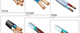
Description and design of the automatic reclosure wire
APV - (aluminum wire APV) with one aluminum core, with PVC insulation.
Explanation of the designation:
“A” at the beginning – aluminum core; "P" - wire; “B” - PVC insulation (vinyl).
Example of designation: APV 2.5 - APV wire with a conductor cross-section of 2.5 mm2
Since the wires are intended mainly for industrial use and are designed for a long service life, GOST sets stringent requirements for finished products in terms of structural, electrical and mechanical parameters. The values of individual parameters are also regulated for the period of operation and storage.
The range of produced sections is from 2 to 120 mm2.
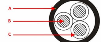
Cores up to 16 mm2 inclusive are made only monolithic, from 25 mm2 and above must be twisted from individual wires (number of wires: at least 7 for sections 25 and 35 mm2; at least 19 for sections 50, 70 and 95 mm2; at least 37 for section 120 mm2).
The insulation must fit tightly to the core and be removed without damaging the core. The nominal and minimum values of the radial insulation thickness and the maximum outer diameter for wires of the most commonly used sections up to 50 mm2 are given in the table.
| Nominal cross-section, mm2 | Nominal insulation thickness, mm | Minimum insulation thickness, mm | Maximum outer diameter, mm |
| 2,5 | 0,8 | 0,62 | 3,9 |
| 4 | 0,8 | 0,62 | 4,4 |
| 6 | 0,8 | 0,62 | 4,9 |
| 10 | 1,0 | 0,8 | 6,4 |
| 16 | 1,0 | 0,8 | 8,0 |
| 25 | 1,2 | 0,98 | 9,8 |
| 35 | 1,2 | 0,98 | 11,0 |
| 50 | 1,4 | 1,16 | 13,0 |
It is allowed to repeat the configuration of the current-carrying core on the insulation surface within permissible deviations.
Wires must be made in different colors. The coloring must be solid or done by applying two longitudinal stripes to the insulation of a natural color, located diametrically. For single-core wires used for grounding purposes, the insulation should be a solid yellow-green color.
The color of solid insulation or longitudinal strips must be specified in the order (the letters indicated in the table are added to the wire designation when ordering, for example: APV Zh 2.5.
| Color | Designation |
| White, natural or gray | B |
| Yellow or orange or purple | AND |
| Red or pink | TO |
| Blue or cyan | WITH |
| Green | Z |
| Brown | Kch |
| Black | H |
| Yellow-green | Z-Z |
If there is no indication of a specific color in the order, the manufacturer supplies wires at its discretion, while it is allowed to supply wires with insulation of transitional and mixed colors (designation “BC”) in a volume of no more than 10% of the batch.
Explanation of markings
Let's begin the description of the autorecloser wire by deciphering the abbreviation. Domestic marking of cable products usually consists of several letters. Each of them has its own meaning and indicates the composition and characteristics of the product. How is the reclosure marking deciphered? It is deciphered as follows:
- A – core material, aluminum;
- P – type of product, wire;
- B – insulation material, PVC.
There is always a number after the marking - this is the number of cores and their cross-sectional area. If there is only one number, then this is only the cross-sectional area. The autoreclose wire is always single-core with one layer of insulation.
Example: APV 4 – cross-sectional area of the current-carrying conductor is 4 sq. mm.
Technical characteristics of the automatic reclosure wire
The electrical resistance of current-carrying conductors at direct current for wires with a cross-section of up to 50 mm2 upon acceptance and delivery must be no more than that indicated in the table.
| Nominal conductor cross-section, mm2 | 2,5 | 4 | 6 | 10 | 16 | 25 | 35 | 50 |
| Copper conductor resistance, Ohm/km | 12,1 | 7,41 | 5,11 | 3,08 | 1,91 | 1,20 | 0,868 | 0,641 |
For the period of operation and storage, it is allowed to increase the specified resistance values of the cores by 20%.
The electrical insulation resistance per 1 km of length at a temperature of 20°C must be at least 1 MOhm upon acceptance and delivery and at least 0.01 MOhm for the period of operation and storage.
Upon acceptance and delivery, finished wires must withstand, when immersed in water without preliminary exposure to it, testing with an alternating voltage of 2000 V at a frequency of 50 Hz for 5 minutes, applied between the conductor and water (for the period of operation and storage - 1000 V under the same conditions).
The wires must withstand winding at a temperature of minus 15°C onto a cylinder (drum) with a diameter equal to 5 outer diameters of the wire (in a special installation directly in the refrigerating chamber).
Main settings
The design of the PRKS wire provides the following parameters and technical characteristics:
- Wire pv-1: technical characteristics, applications and price
- Core flexibility class - III;
- The minimum bending radius is 4 outer diameters;
- Complies with the requirements of the “Technical Regulations in the field of fire safety”, GOST R 53315-2009 – O1.8.2.3.4. Fire hazard indicator—PRGO 1;
And also the following operating conditions:
- Rated voltage 380 and 660V AC with a frequency of up to 400 Hz or 1000V DC.
- The permissible ambient temperature ranges from -60 to +180 degrees Celsius.
- Relative ambient humidity up to 98%.
- The long-term permissible temperature of current-carrying conductors is +180 degrees Celsius.
- Service life for fixed installation is at least 20 years.
- Service life when connected to non-stationary electrical equipment is 12 years.
- The minimum insulation resistance is standard for cable products for voltages up to 1000V - 0.5 MOhm.
- The permissible current for wires with copper conductors and rubber insulation is described in the PUE table. 1.3.4.
- Construction length – at least 100m.
- Resistant to solar radiation, mold fungi, rain, mechanical stress (punching).
Upon request, manufacturers offer oil- and petrol-resistant wires with a permissible temperature of up to 250 degrees Celsius. For rubber this is a critical factor. It is also possible to produce options with a screen made of aluminum-polyethylene tape or polyester lines and any coating color.
According to the specifications, there are requirements for the thickness of insulation and sheathing for various rated voltages, which you can see in the table below.
The wire is produced with a different number of cores (from 1 to 5) with a core cross-section ranging from 0.75 sq. mm up to 16 sq. mm. When connecting three-phase consumers to the network using PRKS, it will withstand a load of up to 45 kW.
PRKS is manufactured not according to GOST, but according to technical specifications, depending on the manufacturer and year of manufacture it can be:
- TU16.K138-001-2006
- TU 16 K71-379-2007
Due to the design, materials and its technical characteristics, the PRKS wire does not spread fire.
You can use the following table to calculate the weight for different wire sizes.
Appv wire: decoding and characteristics
We have looked at the PRKS device, now let's talk about what this wire is used for.
Requirements for marking the automatic reclosure wire
Wires must have the manufacturer's designation and the wire identification, which must be made in the form of a continuous marking on the insulation surface. The marking may be printed, embossed or stamped onto the surface of the wire. The distance from the end of the marking to the beginning of the next one should not exceed 500 mm. It is allowed to mark wires with a cross-section of up to 6 mm2 in the form of a distinctive thread or colored stripes or solid marks.
The label attached to the coil or drum, or on the cheek of the drum, must indicate:
— trademark of the manufacturer; — symbol of the wire (full, indicating the number of cores and cross-section); — length in meters; — gross weight (for drums) in kilograms — date of manufacture (year, month); — GOST designation.
The label must bear a technical control stamp and a certification mark.
For wires supplied on a drum, the label attached to the coil or drum, or on the cheek of the drum, must indicate the number of sections and their length through a plus sign from the top to the bottom layers in meters.
Requirements
To ensure the declared modes and safe operating conditions of the equipment, a number of requirements are imposed on automatic restart devices:
- Performance – must ensure the transition speed determined by the type of powered devices and consumer category. But, at the same time, the speed should not restart until the electric arc has completely dissipated. Because otherwise, even with short-term damage, re-ionization of the insulating gap is possible.
- Resistance to emergency mode - TAVR and backup protection devices should not reduce the quality and speed of response due to changes in electrical quantities.
- Automatic reclosure selectivity - the system must adjust its operation in accordance with other emergency automatic devices, without interrupting the operation of the protection.
Figure 3: Coordination of automatic reclosure with other protections - In case of operational shutdowns for the purpose of carrying out scheduled work, the automatic recloser must be removed from the circuit so as not to mistakenly apply voltage to the substation busbars and not endanger personnel.
- After the reclose has been triggered, the switching device must return to the closed position. If the reclosure is unsuccessful, there should be an automatic return to the open position.
- For some types of protection (gas, differential and others that react to damage to the transformer), a ban on restarting should be established. Also, the disabled position must be maintained in the event of an emergency mode in power electrical machines.
- When restarting, uncontrolled multiple reclosures must be blocked in order to avoid the destructive effects of sustained short-circuit currents on devices.
Figure 4: Current increase during short circuit
Weight and size parameters of the automatic reclosure wire
Approximate weights of the most common wire cross-sections for packaging and transportation purposes are given in the table. The given values may differ for wires of different batches and manufacturers by 10% less or more.
| Section | Weight value for packaging and transportation purposes, kg/km |
| 2,5 | 15,5 |
| 4 | 21 |
| 6 | 29 |
| 10 | 47 |
| 16 | 66 |
| 25 | 114 |
| 35 | 146 |
| 50 | 202 |
Modern microprocessor automatic reclosing devices
Mirex Khabarovsk online store
Microprocessor-based MPD devices occupy the vacated niches of traditional electromechanical and semiconductor devices. These devices also have many disadvantages, which, although they have led to a weakening of the reliability of electrical networks due to the loss and replacement of traditional relay devices, thanks to their constantly growing improvement, they occupy an increasingly important place in the protection of electrical objects.
Rice. No. 4. The UZA-10 RS device is a device for relay protection, automation and control of connections.
Modern microprocessor devices, designed to replace conventional relay protection, are intended for new and reconstructed substations. They adapt to all types of high-voltage circuit breakers and work with various drive mechanisms. UZA-10 RS11 is mounted in relay cabinets of switchgears powered by current transformers and operative voltage supply circuits. Microprocessor units perform the function of a single automatic reclosure. They have an LED indication showing the operation of the protections and the automatic function of the device. Replacing electromechanical and semiconductor relays with new modern microprocessor devices does not require significant changes and reconstruction in existing control and automation circuits. No special installations are required to check devices.
Rice. No. 5. Table of functions performed by a microprocessor device
The functional blocks of microprocessor devices are distinguished by a clear delineation of tasks and are limited exclusively to relay protection functions, this achieves an increase in the degree of reliability to create a new concept for constructing relay protection.
Write comments or additions to the article, maybe I missed something. Take a look at the site map, I will be glad if you find anything else useful on my site.
Automatic reclosure wire load currents
Permissible load currents for wires are not regulated in GOST. In accordance with the PUE, for any installation method it is recommended that for single wires not exceed the load currents indicated in the table.
| Nominal core cross-section, mm2 | Permissible load current, A |
| 2,5 | 24 |
| 4 | 32 |
| 6 | 39 |
| 10 | 60 |
| 16 | 75 |
| 25 | 105 |
| 35 | 130 |
| 50 | 165 |
Cable sizes APV-T
| Name | Availability, m | Price, rub | Quantity, m |
| APV-T 1×400 S | Specify | Specify | |
| APV-T 1×400 Z | Specify | Specify | |
| APV-T 1×400 H | Specify | Specify | |
| APV-T 1×400 Z-Zh | Specify | Specify | |
| APV-T 1×400 Kch | Specify | Specify | |
| APV-T 1×400 | Specify | Specify | |
| APV-T 1×185 Kch | Specify | Specify | |
| APV-T 1×185 | Specify | Specify | |
| APV-T 1×240 B | Specify | Specify | |
| APV-T 1×240 F | Specify | Specify | |
| APV-T 1×240 K | Specify | Specify | |
| APV-T 1×240 S | Specify | Specify | |
| APV-T 1×240 Z | Specify | Specify | |
| APV-T 1×240 H | Specify | Specify | |
| APV-T 1×240 Z-Zh | Specify | Specify | |
| APV-T 1×240 Kch | Specify | Specify | |
| APV-T 1×240 | Specify | Specify | |
| APV-T 1×300 B | Specify | Specify | |
| APV-T 1×300 F | Specify | Specify | |
| APV-T 1×300 K | Specify | Specify | |
| APV-T 1×300 S | Specify | Specify | |
| APV-T 1×300 Z | Specify | Specify | |
| APV-T 1×300 H | Specify | Specify | |
| APV-T 1×300 Z-Zh | Specify | Specify | |
| APV-T 1×300 Kch | Specify | Specify | |
| APV-T 1×300 | Specify | Specify | |
| APV-T 1×400 B | Specify | Specify | |
| APV-T 1×400 F | Specify | Specify | |
| APV-T 1×400 K | Specify | Specify | |
| APV-T 1×120 Kch | Specify | Specify | |
| APV-T 1×120 | Specify | Specify | |
| APV-T 1×150 B | Specify | Specify | |
| APV-T 1×150 F | Specify | Specify | |
| APV-T 1×150 K | Specify | Specify | |
| APV-T 1×150 S | Specify | Specify | |
| APV-T 1×150 Z | Specify | Specify | |
| APV-T 1×150 H | Specify | Specify | |
| APV-T 1×150 Z-Zh | Specify | Specify | |
| APV-T 1×150 Kch | Specify | Specify | |
| APV-T 1×150 | Specify | Specify | |
| APV-T 1×185 B | Specify | Specify | |
| APV-T 1×185 F | Specify | Specify | |
| APV-T 1×185 K | Specify | Specify | |
| APV-T 1×185 S | Specify | Specify | |
| APV-T 1×185 Z | Specify | Specify | |
| APV-T 1×185 H | Specify | Specify | |
| APV-T 1×185 Z-Zh | Specify | Specify | |
| APV-T 1×70 Z | Specify | Specify | |
| APV-T 1×70 H | Specify | Specify | |
| APV-T 1×70 Z-Zh | Specify | Specify | |
| APV-T 1×70 Kch | Specify | Specify | |
| APV-T 1×70 | Specify | Specify | |
| APV-T 1×95 B | Specify | Specify | |
| APV-T 1×95 F | Specify | Specify | |
| APV-T 1×95 K | Specify | Specify | |
| APV-T 1×95 Z-Zh | Specify | Specify | |
| APV-T 1×95 H | Specify | Specify | |
| APV-T 1×95 Z | Specify | Specify | |
| APV-T 1×95 S | Specify | Specify | |
| APV-T 1×120 F | Specify | Specify | |
| APV-T 1×120 B | Specify | Specify | |
| APV-T 1×95 | Specify | Specify | |
| APV-T 1×95 Kch | Specify | Specify | |
| APV-T 1×120 K | Specify | Specify | |
| APV-T 1×120 S | Specify | Specify | |
| APV-T 1×120 Z | Specify | Specify | |
| APV-T 1×120 H | Specify | Specify | |
| APV-T 1×120 Z-Zh | Specify | Specify | |
| APV-T 1×35 Kch | Specify | Specify | |
| APV-T 1×50 S | Specify | Specify | |
| APV-T 1×50 K | Specify | Specify | |
| APV-T 1×50 F | Specify | Specify | |
| APV-T 1×50 B | Specify | Specify | |
| APV-T 1×35 | Specify | Specify | |
| APV-T 1×50 Z | Specify | Specify | |
| APV-T 1×50 H | Specify | Specify | |
| APV-T 1×50 Z-Zh | Specify | Specify | |
| APV-T 1×50 Kch | Specify | Specify | |
| APV-T 1×50 | Specify | Specify | |
| APV-T 1×70 S | Specify | Specify | |
| APV-T 1×70 K | Specify | Specify | |
| APV-T 1×70 F | Specify | Specify | |
| APV-T 1×70 B | Specify | Specify | |
| APV-T 1×16 Kch | Specify | Specify | |
| APV-T 1×16 | Specify | Specify | |
| APV-T 1×25 B | Specify | Specify | |
| APV-T 1×25 F | Specify | Specify | |
| APV-T 1×25 K | Specify | Specify | |
| APV-T 1×25 S | Specify | Specify | |
| APV-T 1×25 Z | Specify | Specify | |
| APV-T 1×25 H | Specify | Specify | |
| APV-T 1×25 Z-Zh | Specify | Specify | |
| APV-T 1×25 Kch | Specify | Specify | |
| APV-T 1×25 | Specify | Specify | |
| APV-T 1×35 B | Specify | Specify | |
| APV-T 1×35 F | Specify | Specify | |
| APV-T 1×35 K | Specify | Specify | |
| APV-T 1×35 S | Specify | Specify | |
| APV-T 1×35 Z | Specify | Specify | |
| APV-T 1×35 H | Specify | Specify | |
| APV-T 1×35 Z-Zh | Specify | Specify | |
| APV-T 1×6 Kch | Specify | Specify | |
| APV-T 1×6 | Specify | Specify | |
| APV-T 1×10 B | Specify | Specify | |
| APV-T 1×10 F | Specify | Specify | |
| APV-T 1×10 K | Specify | Specify | |
| APV-T 1×10 S | Specify | Specify | |
| APV-T 1×10 Z | Specify | Specify | |
| APV-T 1×10 H | Specify | Specify | |
| APV-T 1×10 Z-Zh | Specify | Specify | |
| APV-T 1×10 Kch | Specify | Specify | |
| APV-T 1×10 | Specify | Specify | |
| APV-T 1×16 B | Specify | Specify | |
| APV-T 1×16 F | Specify | Specify | |
| APV-T 1×16 K | Specify | Specify | |
| APV-T 1×16 S | Specify | Specify | |
| APV-T 1×16 Z | Specify | Specify | |
| APV-T 1×16 H | Specify | Specify | |
| APV-T 1×16 Z-Zh | Specify | Specify | |
| APV-T 1×2.5 H | Specify | Specify | |
| APV-T 1×2.5 Z-Zh | Specify | Specify | |
| APV-T 1×2.5 Kch | Specify | Specify | |
| APV-T 1×2.5 | Specify | Specify | |
| APV-T 1×4 B | Specify | Specify | |
| APV-T 1×4 F | Specify | Specify | |
| APV-T 1×4 K | Specify | Specify | |
| APV-T 1×4 S | Specify | Specify | |
| APV-T 1×4 Z | Specify | Specify | |
| APV-T 1×4 H | Specify | Specify | |
| APV-T 1×4 Z-Zh | Specify | Specify | |
| APV-T 1×4 Kch | Specify | Specify | |
| APV-T 1×4 | Specify | Specify | |
| APV-T 1×6 B | Specify | Specify | |
| APV-T 1×6 F | Specify | Specify | |
| APV-T 1×6 H | Specify | Specify | |
| APV-T 1×6 Z | Specify | Specify | |
| APV-T 1×6 S | Specify | Specify | |
| APV-T 1×6 K | Specify | Specify | |
| APV-T 1×6 Z-Zh | Specify | Specify | |
| APV-T 1×2.5 B | Specify | Specify | |
| APV-T 1×2.5 F | Specify | Specify | |
| APV-T 1×2.5 K | Specify | Specify | |
| APV-T 1×2.5 S | Specify | Specify | |
| APV-T 1×2.5 Z | Specify | Specify |
Available methods for quality control of automatic reclosure wire
Control methods are presented that, while not strictly complying with GOST, allow preliminary conclusions to be drawn about the quality of the wire if the measured values differ significantly from the regulated ones. The final conclusion about the compliance of the wire with GOST can be made only after testing the wire in a specialized laboratory using strict methods and in the volumes specified in GOST.
Visual inspection The following can be checked: markings, number of wires in the core, color and integrity of the insulation.
Measuring structural dimensions The insulation thickness and outer diameter can be checked using suitable measuring tools. Measuring the wire diameter dpr and calculating the cross-section of the core using the formula 0.785dpr2N (where N is the number of wires in the core) is not a strict method for controlling the cross-section of the cores, because confirmation of cross-section compliance is electrical resistance, however, a significant deviation of the calculated cross-section from the nominal (more than 10%) may serve as a basis for doubts about the quality.
Measuring the electrical resistance of current-carrying conductors can be carried out on a finished wire with an ohmmeter with a suitable measurement limit (with a small cross-section and the normal length of the wire in a coil or on a drum can be several Ohms) and recalculated to a length of 1 km. Particular attention should be paid to making good contact with the test leads.
Main purposes of application
In electrical networks, all types of damage can be divided into two groups:
- sustainable;
- unstable.
Persistent types include damage to the electrical network that does not recover on its own over time. To eliminate them, the help of specialists, or rather, an emergency team, is required. Such damage most often includes rupture of wires or damage to a section of the line, due to which further operation of the electrical network is impossible.
Unstable type damage is characterized by voltage restoration some time after the breakdown. For example, such a breakdown may occur after the wires are caught together, and an electric arc occurs, which does not cause significant damage to the electrical network. Due to the small amount of time during a short circuit, the entire power circuit is under relay protection. In practice, the number of intermittent faults is about 50–90% of all cases of electrical network breakdowns.
After a breakdown, it is the autorecloser that is responsible for restarting the network section. Automatic restart of voltage may or may not be successful. If after a breakdown the voltage is restored, then the problem can be attributed to the unstable type. If the voltage during automatic reclosure is not restored after a short period of time, it means that the type of damage is stable.
Solving the problem is possible without the presence of the system, but this device is responsible for accelerating the recovery process, and also completely takes over the automation work.
The automatic reclosing and automatic reclosing device system itself has become widespread and is used in electrical networks and substations. The device is combined with other types of relay automation, which makes it possible to fully automate work at substations, while eliminating the need to use an operational worker directly at the power grid facility. Also, the use of an automatic restart device at substations makes it possible to avoid the factor of errors during the work of maintenance personnel.
As indicated in the PUE, the automatic reclosure device must be used on all cable-overhead and overhead lines that have an operating voltage of 1 kV or higher. Additionally, transformers, electric motors, and substation busbars can be equipped with an automatic restart system.
Purpose of automatic reclosing
Rice.
1: Purpose of automatic reclosure Automatic reclosing is designed to close circuit breakers after an emergency shutdown has de-energized the line. At the same time, automatic reclosure makes it possible to reduce interruptions in power supply by the number of short-term accidents. Look at Figure 1, in the event of a short circuit at point K1 followed by tripping of the high-voltage switch Q1, automatic reclosure 1 is triggered. Let’s assume that the short circuit has resolved itself and the supply to the line from substation PS1 to PS2 has been restored. At the same time, when there is a short circuit at points K2 and K3, switch Q2 cuts off the line to substation PS3. Let’s assume that these are established short circuits; when autorecloser2 is triggered, the voltage will be supplied to the network again, but since a short circuit occurs at points K2 and K3, Q2 will turn off the line again.
Therefore, all emergency situations according to their duration can be divided into:
- Short-term - those that are caused by a relatively short-term factor (movement of animals, falling branches and other elements), which created the flow of short circuit currents for a fraction or a few seconds, after which both the cause and the circuit eliminated themselves.
- Established - caused by a constant factor that cannot go away without personnel intervention (wire breakage, insulation destruction, etc.). In such situations, persistent short circuits occur, which can only be eliminated by turning off the switches and subsequent repairs.
In practice, automatic re-closing works in all situations, but successful re-closing only occurs when the cause has been eliminated, that is, in the case of short-term faults. If, after the first restart, automatic recovery does not occur, depending on the type, the following restart stages may be applied. Depending on local conditions, automatic reclosure systems may have different operating features.
Since 50% of all outages can be re-energized with a single autorecloser, the first stage is considered the most effective. The second is adjusted with a time interval of several seconds or tens of seconds, and, as statistics show, it allows the consumer to be powered in another 15% of cases.
Requirements
To ensure normal operation, the AFR must meet the following requirements:
- successfully eliminate emergency situations of various types - triggering, regardless of the extent of the damage;
- perform a shutdown in accordance with the established settings for time and the magnitude of the characteristics deviation;
- de-energize the minimum number of consumers;
- provide for the possibility of stepwise shutdown;
- exclude spontaneous operation without appropriate grounds.
The listed conditions are intended to ensure normal operation of the equipment and its proper protection.