Electrical diagrams. Types of circuits
Hello Habr! More often, articles provide colorful pictures instead of electrical diagrams, which causes disputes in the comments. In this regard, I decided to write a short educational article on the types of electrical circuits classified in the Unified System of Design Documentation (ESKD)
.
Throughout the entire article I will rely on the ESKD. Let's consider GOST 2.701-2008 Unified System of Design Documentation (ESKD).
Scheme. Types and types. General requirements for implementation . This GOST introduces the concepts:
- type of circuit
- a classification grouping of circuits, distinguished according to the principle of operation, the composition of the product and the connections between its components; - scheme type
- a classification grouping distinguished based on their main purpose.
Let's immediately agree that we will have only one type of circuit - an electrical circuit (E)
. Let's figure out what types of circuits are described in this GOST.
| Circuit type | Definition | Circuit type code |
| Structural diagram | A document defining the main functional parts of the product, their purpose and relationships | 1 |
| Functional diagram | A document explaining the processes occurring in individual functional circuits of the product (installation) or the product (installation) as a whole | 2 |
| Schematic diagram (complete) | A document that defines the full composition of elements and the relationships between them and, as a rule, gives a complete (detailed) understanding of the principles of operation of the product (installation) | 3 |
| Connection diagram (installation) | A document showing the connections of the component parts of the product (installation) and defining the wires, harnesses, cables or pipelines by which these connections are made, as well as the places of their connections and input (connectors, boards, clamps, etc.) | 4 |
| Connection diagram | Document showing external connections of the product | 5 |
| General scheme | A document defining the components of the complex and their connections to each other at the site of operation | 6 |
| Layout diagram | A document defining the relative location of the components of the product (installation), and, if necessary, also bundles (wires, cables), pipelines, optical fibers, etc. | 7 |
| Combined scheme | A document containing elements of different types of circuits of the same type | 0 |
| Note - The names of the types of circuits indicated in brackets are established for electrical circuits of power structures. | ||
Next, we will consider each type of circuit in more detail as applied to electrical circuits.
Main document: GOST 2.702-2011 Unified system of design documentation (ESKD).
Rules for executing electrical circuits .
So, what is it and what do these electrical circuits “eat” with? GOST 2.702-2011 will give us the answer: Electrical diagram
is a document containing, in the form of conventional images or symbols, the components of a product operating with the help of electrical energy, and their interconnections
.
Depending on the main purpose, electrical circuits are divided into the following types:
Electrical structural diagram (E1)
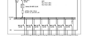
The block diagram shows all the main functional parts of the product (elements, devices and functional groups) and the main relationships between them. The graphical construction of the diagram should provide the best idea of the sequence of interaction of functional parts in the product. On the interconnection lines, it is recommended to use arrows to indicate the direction of the processes occurring in the product. An example of an electrical structural diagram:
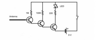
Electrical functional diagram (E2)
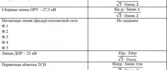
A functional diagram depicts the functional parts of a product (elements, devices and functional groups) participating in the process illustrated by the diagram, and the connections between these parts. The graphical construction of the diagram should give the most visual representation of the sequence of processes illustrated by the diagram. An example of an electrical functional diagram:
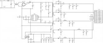
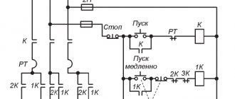
Electrical circuit diagram (complete) (E3)
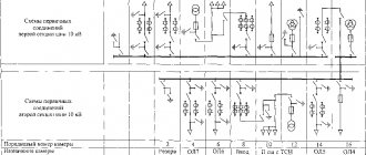
The circuit diagram shows all the electrical elements or devices necessary for the implementation and control of established electrical processes in the product, all the electrical connections between them, as well as the electrical elements (connectors, clamps, etc.) that terminate the input and output circuits. The diagram may depict connecting and mounting elements installed in the product for structural reasons. The circuits are performed for products in the off position. An example of an electrical circuit diagram:
Electrical connection diagram (installation) (E4)
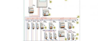
The connection diagram should show all devices and elements included in the product, their input and output elements (connectors, boards, clamps, etc.), as well as connections between these devices and elements. The location of graphic symbols of devices and elements on the diagram should approximately correspond to the actual placement of elements and devices in the product. The arrangement of images of input and output elements or terminals within graphic symbols and devices or elements should approximately correspond to their actual placement in the device or element. Example of electrical connection diagram:
Electrical connection diagram (E5)
The connection diagram must show the product, its input and output elements (connectors, clamps, etc.) and the ends of wires and cables (stranded wires, electrical cords) connected to them for external installation, near which data on connecting the product (characteristics) should be placed external circuits and (or) addresses). The placement of images of input and output elements inside the graphic designation of the product should approximately correspond to their actual placement in the product. The diagram should indicate the positional designations of the input and output elements assigned to them on the circuit diagram of the product. Example of electrical connection diagram:
General electrical circuit (E6)
The general diagram shows the devices and elements included in the complex, as well as the wires, bundles and cables (stranded wires, electrical cords) connecting these devices and elements. The location of graphic symbols of devices and elements on the diagram should approximately correspond to the actual placement of elements and devices in the product. Example of a general electrical diagram:
Electrical layout diagram (E7)
The layout diagram shows the component parts of the product, and, if necessary, the connections between them - the structure, room or area on which these components will be located. Example of electrical layout:
Combined electrical circuit (E0)
This type of diagram shows various types that are combined with each other in one drawing. An example of a combined electrical circuit:
PS
This is my first article on Habré, don’t judge strictly.
Country house electrification project. Three-phase or single-phase network?
Of course, before drawing any diagrams and going to make the connection, you will need to decide on the type of power supply, its source, etc.
In private houses, as in city apartments, a three-phase or single-phase network can be used. Both varieties have both their disadvantages and advantages. Initially, any industrial network has three phases. In high-rise buildings they are usually distributed among apartments. Moreover, due to the difference in the number of electrical appliances used, the load on the phase wires is often different. As a result, the neutral wire sometimes burns out. In a private house, such problems usually do not arise, since there is only one owner, and therefore it is much easier to control the load during phase distribution. However, if the network is used incorrectly, all sorts of problems - even failure of electrical appliances - can arise in this case too. To prevent such troubles, you should use a stabilizer, which is very expensive. In addition, you will have to purchase equipment and elements designed specifically for a three-phase line. Which will also cost a pretty penny. Therefore, a three-phase power supply circuit for a private home should be used when there is really a need for it. That is, if it is planned to install very powerful devices or equipment - machines, electric stoves, etc.
The advantage of single-phase networks is their relative low cost and ease of use. The disadvantage is that the power is not very high. It is more appropriate to install such a network in small residential or country houses.
Circuit elements
Any electrical circuit consists of a set of connections and parts. Conventionally, it is often divided into a primary part and a secondary part. In radio electronics, the primary circuit includes the power part, and the secondary circuit includes the executive part. In electrical engineering, this division occurs based on voltage.
Thus, the main circuit circuits include elements involved in the generation and transformation of the main flow of electricity. Through them, the signal reaches the electrical equipment of the final power supply system. Secondary electrical circuits include areas where the power usually does not exceed one kilowatt. They are designed to monitor, measure or account for energy consumption , and control the operation of devices.
All the elements that make up the drawing are usually divided into three groups:
- power supplies and signal generators;
- energy converters, most often receivers;
- elements that ensure the transfer of electricity between parts of the circuit, that is, from the energy source to the final consumer.
The areas through which equal currents pass are called branches, and the junction of two or more branches is called a node. Depending on the number of closed circuits in the circuit, plans are called single- and multi-circuit. All parts that make up the diagram are indicated by signs. They are conventionally divided into electrical and electronic.
You might be interested in this: Connection diagram for a single-phase electricity meter Mercury 201
Image principles
The designation system is carried out in accordance with accepted GOST recommendations. The end terminals of a single-standing element are signed with numbers or indicating its terminals with letter designations. Numbering starts from the point signed with a smaller number.
If a group of identical elements is drawn on a circuit diagram, then their conclusions are indicated on it as follows:
- in front of the number, a letter is drawn indicating the sign of the element or the phase, for example, C – capacitor, T – transistor, U, V, W – phases in a three-phase circuit;
- for identical parts or different outputs of one element, for example, a microcircuit or a resistance store, their outputs are indicated by two numbers separated by a dot;
- the entire group is surrounded by a dotted line indicating a node.
Schemes can be performed in both multi-line and single-line images. The terminals of parts or parts that are not involved in the flow of current are designated shorter than the contacts of the elements used. Different circuits are separated by functionality by the thickness of the lines. But it is not recommended to use more than three thicknesses on the plan.
To simplify the circuit, it is allowed to combine electrically unrelated circuits into a group communication line, but when moving on to the details, each line is isolated separately. If the connector is branched, the number is indicated on it, but at least twice.
The diagram also indicates:
- functional group designation;
- a simplified image of an electronic or electrical device in the form of a rectangle, in the middle of which is its designation, number on the circuit diagram, name, class.
Designations are indicated on top of the location of the elements or with their slight offset to the right side, in free areas and without intersecting with other symbols. In this case, the names of the connection of the end of the section or the beginning may be indicated on the drawing.
Common signs
By opening GOST or a radio amateur's handbook, you will find that there are more than several hundred symbols. And this is not surprising, since, in addition to many radio components and their subtypes, there are images of switching devices, different types of wires and cables, and types of signals.
Therefore, their detailed indication will take several sheets, but for an example and concept of the approach to performing images, you should indicate the most common symbols that can be found in almost any description of an electrical circuit.
So, the key radioelements are designated as follows:
The graphic designation to some extent emphasizes the functional purpose of a particular electronic device. The inductance is made in the form of coil turns, the capacitor - parallel lines, emphasizing the use of plates and a dielectric layer. Arrows used in drawings indicate the direction of flow of current or converted energy.
No exception are the symbols used to indicate electrical wiring elements. They are also standardized. It is not difficult for a knowledgeable person to understand how the circuit diagram is structured and what parts it consists of. At the same time, the contents of the shields also have their own designation. Thus, circuit breakers and residual current devices are depicted as a group of switching contacts indicating a letter code.
To indicate the different shapes and polarities of electrical signals, simple lines are used to depict their appearance. For example, a constant signal is drawn as a straight line, and a variable frequency signal is drawn as a wavy one. High-frequency - three wavy stripes located one below the other. A rectangular impulse or an acute one, respectively, a rectangle (letter P) or a triangle without a base.
Considerable importance in the designations is given to wires, cables and screens. In particular, the figure indicates the complete or partial shielding of the wire, its connection to ground, branch and connection. At the same time, the icons themselves can be made in different colors to make it visually easier to perceive which group the connectors belong to.
Reading a document
Knowing what kinds of icons there are and understanding what they mean, it will not be difficult to read and understand any circuit diagram. Since a schematic diagram is nothing more than a graphical representation of all its elements included in the device with connecting conductors. It is the fundamental document for the design of any electrical circuit system or electronic device. Therefore, even a novice electrician or radio amateur should be able to read it. It is a correct understanding of the drawing that helps master the basics of design, and helps craftsmen quickly and effectively repair damage.
You might be interested in this: Digital multimeter and multitester measurement
First of all, the elements that make up the product or system are studied. The diagram shows the main components and their purpose. Each node is studied separately. If there are no accompanying explanations for the diagram describing its operation, its operating principle can be figured out independently on the basis of the drawn details. For this, reference books or datasheets produced by parts manufacturers are used. They usually indicate in detail how their element can be used in an electrical circuit with the types of its inclusion and parameters.
Secondly, attention is drawn to the clarifying information indicated next to each element and key points of the diagram. Thanks to it, it will be easy to determine which part is used in this place or how the signal changes after passing a certain node.
For example, a bipolar transistor has at least three terminals. In this case, to determine its connection to electrical connections, the letter designation of the element base is used. If the type of part is not clear, you should pay attention to its name and serial number in the diagram. Having remembered this information, identify the element, possibly using a specification. This is a separate document or a table indicated next to the diagram containing a list of all components used to construct a device or circuit.
Direct reading of the circuit occurs from left to right and starts from the point where the input signal is supplied to the device. Next, the path of its passage through electrical connections is monitored, right up to the exit of the product or system.