Three circuits of simple current regulators
There are a lot of voltage regulator circuits on the network for a variety of purposes, but with current regulators things are different. And I want to fill this gap a little, and present to you three simple DC regulator circuits that are worth adopting, as they are universal and can be used in many homemade designs.
In theory, current regulators are not much different from voltage regulators. Please do not confuse current regulators with current stabilizers; unlike the former, they maintain a stable output current regardless of the input voltage and output load.
A current stabilizer is an integral part of any normal laboratory power supply or charger; it is designed to limit the current supplied to the load. In this article we will look at a couple of stabilizers and one regulator for general use.
In all three options, shunts, essentially low-resistance resistors, are used as a current sensor. To increase the output current of any of the listed circuits, it will be necessary to reduce the shunt resistance. The required current value is set manually, usually by rotating a variable resistor. All three circuits operate in linear mode, which means the power transistor will become very hot under heavy loads.
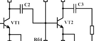
The first scheme is characterized by maximum simplicity and accessibility of components. There are only two transistors, one of them is the control one, the second is the power transistor, through which the main current flows.
The current sensor is a low-resistance wirewound resistor. When connecting an output load, a certain voltage drop is formed across this resistor; the more powerful the load, the greater the drop. This voltage drop is enough to trigger the control transistor; the greater the drop, the more the transistor is open. Resistor R1 sets the bias voltage for the power transistor, it is thanks to it that the main transistor is in the open state. Current limitation occurs due to the fact that the voltage at the base of the power transistor, which was formed by resistor R1, roughly speaking, is damped or shorted to the power ground through the open junction of the low-power transistor, this will close the power transistor, therefore, the current flowing through it decreases down to complete zero .
Resistor R1 is essentially an ordinary voltage divider, with which we can set the degree of opening of the control transistor, and therefore control the power transistor by limiting the current flowing through it.
The second circuit is based on an operational amplifier. It has been used several times in chargers for car batteries. Unlike the first option, this circuit is a current stabilizer.
As in the first circuit, there is also a current sensor (shunt), the operational amplifier records the voltage drop across this shunt, all according to the circuit already familiar to us. The operational amplifier compares the voltage on the shunt with the reference voltage, which is set by the zener diode. With a variable resistor we artificially change the reference voltage. The operational amplifier, in turn, will try to balance the voltage at the inputs by changing the output voltage.
The output of the op-amp drives a high-power field-effect transistor. That is, the principle of operation is not much different from the first circuit, except that there is a reference voltage source made on a zener diode.
This circuit also operates in linear mode and the power transistor will become very hot under heavy loads.
The latest circuit is based on the popular LM317 stabilizer integrated circuit. This is a linear voltage stabilizer, but it is possible to use the microcircuit as a current stabilizer.
The required current is set by a variable resistor. The disadvantage of the circuit is that the main current flows precisely through the previously indicated resistor and naturally it needs a powerful one; the use of wirewound resistors is highly desirable.
The maximum permissible current for the LM317 microcircuit is 1.5 amperes; it can be increased with an additional power transistor. In this case, the microcircuit will already act as a control chip, so it will not heat up, instead the transistor will heat up and there is no escape from it.
Every car owner needs a battery charger, but it costs a lot, and regular preventive trips to a car service center are not an option. Battery service at a service station takes time and money. In addition, with a discharged battery, you still need to drive to the service station. Anyone who knows how to use a soldering iron can assemble a working charger for a car battery with their own hands.
How does such a device work?
The characteristics described below will correspond to most circuits.
In this case, there is a certain area that will be under special stress. When the effect of the positive half-wave ends and a new period of movement with a negative half-wave begins, one of these thyristors will begin to close, and at the same time a new thyristor will open.
Instead of the words positive and negative wave, you should use the first and second (half-wave).
The principle of operation of the second circuit will be exactly the same, but it will control only one of the half-waves of alternating current. After the user understands the principle of operation of the device and its general structure, he will be able to understand how to assemble or, if necessary, repair the thyristor power regulator himself.
A little theory about batteries
Any battery is a storage device for electrical energy. When voltage is applied to it, energy is stored due to chemical changes inside the battery. When a consumer is connected, the opposite process occurs: a reverse chemical change creates voltage at the terminals of the device, and current flows through the load. Thus, in order to get voltage from the battery, you first need to “put it down,” that is, charge the battery.
Almost any car has its own generator, which, when the engine is running, provides power to the on-board equipment and charges the battery, replenishing the energy spent on starting the engine. But in some cases (frequent or difficult engine starts, short trips, etc.) the battery energy does not have time to be restored, and the battery is gradually discharged. There is only one way out of this situation - charging with an external charger.
Read also: Can a burner be used as a soldering iron?
How to find out the battery status
To decide whether charging is necessary, you need to determine the state of the battery. The simplest option - “turns/does not turn” - is at the same time unsuccessful. If the battery “doesn’t turn”, for example, in the garage in the morning, then you won’t go anywhere at all. The “does not turn” condition is critical, and the consequences for the battery can be dire.
The optimal and reliable method for checking the condition of a battery is to measure the voltage on it with a conventional tester. At an air temperature of about 20 degrees, the dependence of the degree of charge on the voltage at the terminals of a battery disconnected from the load (!) is as follows:
- 12.6…12.7 V - fully charged;
- 12.3…12.4 V - 75%;
- 12.0…12.1 V - 50%;
- 11.8…11.9 V - 25%;
- 11.6…11.7 V - discharged;
- below 11.6 V - deep discharge.
It should be noted that the voltage of 10.6 volts is critical. If it drops below, the “car battery” (especially a maintenance-free one) will fail.
Correct charging
There are two methods of charging a car battery - constant voltage and constant current. Each has its own characteristics and disadvantages:
- Constant voltage charging - suitable for restoring the charge of not completely discharged batteries, the voltage at the terminals of which is not lower than 12.3 V. The process is as follows: a direct current source with a voltage of 14.2–14.7 V is connected to the battery terminals. The end of the process is monitored by the current consumption: when it drops to zero, charging is considered complete. The disadvantage of this method is that the initial charging current may be high; The more the battery is discharged, the higher the current. The advantages of the method are obvious - you do not need to constantly adjust the charging current, and the battery is not in danger of being overcharged if you forget about it.
- DC charging is the most common and reliable method. In this mode, the charger produces a constant current equal to 1/10 of the battery capacity. The end of the charging process is determined by the voltage on the battery - when it reaches 14.7 V, the battery stops charging. The disadvantage of this method is that the battery can be damaged if you do not remove it from charging in time.
Assembly and testing
The case is selected individually. You can glue it yourself from plastic, or buy something more or less suitable. The locations for the output of LEDs and manual control buttons are determined after fixing the board. If desired, you can make a hole for a trim resistor.
Do not try to immediately take a very small case.
To test the battery charge controller, you will need an adjustable DC\DC converter, which will simulate the voltage at the battery terminals.
The normally open output of the relay is connected to the multimeter in dial mode.
When the battery is charged and the load is connected to it, the multimeter emits a continuous signal, and the blue LED lights up on the controller.
As soon as the voltage drops below the set limit, charging starts. The red LED on the charge controller lights up, and the indication on the multimeter display changes.
That's it, the battery charge controller is ready, you can use it.
You might also like the following materials:
Thank you for reading to the end! Also Don't forget if you liked the article!
Follow us on Twitter:
Share with friends, leave your comments
Add to our group on VK:
ALTER220 Portal about alternative energy
and suggest topics for discussion, together it will be more interesting!!!
Homemade battery chargers
Assembling a charger for a car battery with your own hands is realistic and not particularly difficult. To do this, you need to have basic knowledge of electrical engineering and be able to hold a soldering iron in your hands.
Simple 6 and 12 V device
This scheme is the most basic and budget-friendly. Using this charger, you can efficiently charge any lead-acid battery with an operating voltage of 12 or 6 V and an electrical capacity of 10 to 120 A/h.
The device consists of a step-down transformer T1 and a powerful rectifier assembled using diodes VD2-VD5. The charging current is set by switches S2-S5, with the help of which quenching capacitors C1-C4 are connected to the power circuit of the primary winding of the transformer. Thanks to the multiple “weight” of each switch, various combinations allow you to stepwise adjust the charging current in the range of 1–15 A in 1 A increments. This is enough to select the optimal charging current.
For example, if a current of 5 A is required, then you will need to turn on the toggle switches S4 and S2. Closed S5, S3 and S2 will give a total of 11 A. To monitor the voltage on the battery, use a voltmeter PU1, the charging current is monitored using an ammeter PA1.
The design can use any power transformer with a power of about 300 W, including homemade ones. It should produce a voltage of 22–24 V on the secondary winding at a current of up to 10–15 A. In place of VD2-VD5, any rectifier diodes that can withstand a forward current of at least 10 A and a reverse voltage of at least 40 V are suitable. D214 or D242 are suitable. They should be installed through insulating gaskets on a radiator with a dissipation area of at least 300 cm2.
Capacitors C2-C5 must be non-polar paper with an operating voltage of at least 300 V. Suitable, for example, are MBChG, KBG-MN, MBGO, MBGP, MBM, MBGCh. Similar cube-shaped capacitors were widely used as phase-shifting capacitors for electric motors in household appliances. A DC voltmeter of type M5−2 with a measurement limit of 30 V was used as PU1. PA1 is an ammeter of the same type with a measurement limit of 30 A.
The circuit is simple, if you assemble it from serviceable parts, then it does not need adjustment. This device is also suitable for charging six-volt batteries, but the “weight” of each of the switches S2-S5 will be different. Therefore, you will have to navigate the charging currents using an ammeter.
With continuously adjustable current
Using this scheme, it is more difficult to assemble a charger for a car battery with your own hands, but it can be repeated and also does not contain scarce parts. With its help, it is possible to charge 12-volt batteries with a capacity of up to 120 A/h, the charge current is smoothly regulated.
The battery is charged using a pulsed current; a thyristor is used as a regulating element. In addition to the knob for smoothly adjusting the current, this design also has a mode switch, when turned on, the charging current doubles.
The charging mode is controlled visually using the RA1 dial gauge. Resistor R1 is homemade, made of nichrome or copper wire with a diameter of at least 0.8 mm. It serves as a current limiter. Lamp EL1 is an indicator lamp. In its place, any small-sized indicator lamp with a voltage of 24–36 V will do.
Read also: Symbols in the drawing
A step-down transformer can be used ready-made with an output voltage on the secondary winding of 18–24 V at a current of up to 15 A. If you don’t have a suitable device at hand, you can make it yourself from any network transformer with a power of 250–300 W. To do this, wind all windings from the transformer except the mains winding, and wind one secondary winding with any insulated wire with a cross-section of 6 mm. sq. The number of turns in the winding is 42.
Thyristor VD2 can be any of the KU202 series with the letters V-N. It is installed on a radiator with a dispersion area of at least 200 sq. cm. The power installation of the device is done with wires of minimal length and with a cross-section of at least 4 mm. sq. In place of VD1, any rectifier diode with a reverse voltage of at least 20 V and withstanding a current of at least 200 mA will work.
Setting up the device comes down to calibrating the RA1 ammeter. This can be done by connecting several 12-volt lamps with a total power of up to 250 W instead of a battery, monitoring the current using a known-good reference ammeter.
From a computer power supply
To assemble this simple charger with your own hands, you will need a regular power supply from an old ATX computer and knowledge of radio engineering. But the characteristics of the device will be decent. With its help, batteries are charged with a current of up to 10 A, adjusting the current and charge voltage. The only condition is that the power supply is desirable on the TL494 controller.
To create a car charger with your own hands from a computer power supply, you will have to assemble the circuit shown in the figure.
The step-by-step operations required for finalization will look like this:
- Bite off all the power bus wires, with the exception of the yellow and black ones.
- Connect the yellow and separately black wires together - these will be the “+” and “-” chargers, respectively (see diagram).
- Cut all traces leading to pins 1, 14, 15 and 16 of the TL494 controller.
- Install variable resistors with a nominal value of 10 and 4.4 kOhm on the power supply casing - these are the controls for regulating the voltage and charging current, respectively.
- Using a suspended installation, assemble the circuit shown in the figure above.
If the installation is done correctly, then the modification is complete. All that remains is to equip the new charger with a voltmeter, an ammeter and wires with alligator clips for connecting to the battery.
In the design it is possible to use any variable and fixed resistors, except for the current resistor (the lower one in the circuit with a nominal value of 0.1 Ohm). Its power dissipation is at least 10 W. You can make such a resistor yourself from a nichrome or copper wire of the appropriate length, but you can actually find a ready-made one, for example, a 10 A shunt from a Chinese digital tester or a C5-16MV resistor. Another option is two 5WR2J resistors connected in parallel. Such resistors are found in switching power supplies for PCs or TVs.
Methods for adjusting the output current
When the need arises to reduce the output current, this can be done in various ways. The following describes the most commonly used options for limiting the battery charging current:
- As you know, current and voltage obey Ohm's law. Thus, in order to reduce the current, you need to increase the resistance. One way to do this is to connect a rheostat.
- In some cases, a light bulb is connected to the input of the charger, which reduces the current strength through its electricity consumption.
- If the charger uses a transformer, then its output parameters can be adjusted by reducing the number of turns of the secondary winding. As is known, in rectifiers, alternating current is usually supplied to the primary. It creates a magnetic field, which through the core generates a current of a given value due to the phenomenon of induction. It depends on the number of turns of the winding. The fewer there are, the weaker the current. Next, rectification occurs and a constant voltage is supplied to the output terminals of the charger.
- Fuses or switches open the circuit when the limit value is exceeded. Some of them provide automatic switching on after the electrical parameters meet the standards. Others may have a button installed for this. In this case, the decision to continue working is made by the person.
- Sometimes, at the very beginning of the charging process, a large current may pass through the circuit in the first seconds, which is significantly higher than usual. In this case, thermistors can be used to protect the equipment. The peculiarity of their action is that they change resistance depending on temperature. While the parts are not heated, it is significant. Subsequently, it decreases and moves into the range of normal operating values. This creates reliable protection against inrush current.
- Active loads are circuits using transistors and diodes. They are designed to dynamically limit the current, adjusting to its values at each moment.
- Current-limiting diodes are used for regulation. They can be used for different voltage levels.
When selecting the correct resistance, it is necessary to take into account that which is available in the power supply and internal in the battery. When using the methods described here, you may encounter some difficulties. They can be of different nature.
Using a pulse charger Source stroyvolga.ru
You need to take into account the differences between batteries. Those that are used for mobile gadgets are often used. A small current passes through them. If it is exceeded, it may damage the charger, and in some cases, the gadget. It is important to accurately calculate the amount of additional load.
By watching the video, you can learn how to limit the charger current:
What you need to know when charging a battery
When charging a car battery, it is important to follow a number of rules. This will help you extend your battery life and maintain your health:
- All lead batteries are charged with a current no higher than one tenth of the battery capacity. If you have a battery with a capacity of 60 A/h in your car, then the calculation of the charging current looks like this: 60/10 = 6 A.
- Explosive gases may be released during charging. This is especially true for serviceable batteries. One spark is enough for hydrogen accumulated in a garage or other room to explode. Therefore, you need to charge batteries in a well-ventilated area or on a balcony.
- Charging the battery is accompanied by the release of heat, so constantly monitor the temperature of the battery case by touch. If the battery becomes noticeably hot, immediately reduce the charging current or stop charging altogether.
- If the battery is serviceable, constantly monitor the electrolyte level in the banks and its density. During the charging process, the electrolyte “boils away” and the density increases. If the plates in the jar are exposed or the density rises above 1.29, and charging is not yet complete, add distilled water to the electrolyte.
- Do not overcharge the battery. The maximum voltage on it with the charger connected is 14.7 V.
- Do not allow the battery to be deeply discharged; recharge it periodically. If the voltage on the battery drops below 10.7 when the load is off, the battery will have to be thrown away.
The question of creating a simple battery charger with your own hands has been clarified. Everything is quite simple, all you have to do is stock up on the necessary tools and you can safely get to work.
Hello everyone, friends, in this post I want to tell you about a current stabilizer for a charger that almost everyone can assemble with their own hands.
What is the battery controller for?
Despite the fact that the capacity of modern batteries, as well as their functionality, has increased significantly, the charging algorithm has remained virtually unchanged. When the battery is discharged, special equipment is connected to it, which, by stimulating chemical reactions in the battery, replenishes its capacity.
Important! If you do not stop charging in a timely manner, the battery may overheat and even explode. In a situation where there is not enough current to replenish the charge, the battery cannot restore its capacity; being in a discharged state for a long time can significantly reduce its service life
In order for all processes to occur correctly, and the battery built into the mobile device to work as long as possible, a battery charge controller is needed. At its core, as a rule, there are two resistors that control the upper and lower voltage limits. At the very beginning of energy replenishment, they pass the maximum current through themselves, then they gradually reduce it, protecting the battery from overcharging. If the voltage is below the minimum required, the resistor supplements it to the required level using previously accumulated energy.
A battery charge controller is required in laptops, mobile phones, portable cash registers, tablets, and so on. It is also installed in renewable energy sources, since the principle of their operation is to accumulate energy in a special battery during periods of solar or wind activity, and then transfer it to the consumer. To control these procedures, the described element is needed in this equipment.
Using devices to monitor battery charge
FakeHeader
Comments 102
Is there a file for the printed circuit board?
How many volts are lost at the output?
I did everything according to your scheme. The current is regulated only between 4-5A! tell me what the problem is!
But no one said a word about the choice of transistor and possibly radiator :). It’s even easier to make a current limiter on lm317, then essentially one TO-220 body and a couple of resistors