Let's look at the types of manually operated mechanical switches, as well as their parameters and applications in electronic circuits.
What is a switch
Switches are elements that control the flow of electrical current in a circuit and play a key role where user interaction is required. These elements can only be in one of two states: open or closed. In the open (off) state, the switch is simply an open circuit. As a result, the circuit is broken, preventing current from flowing. When it is closed (on), the switch acts as a normal conductor (has resistance, inductance) through which electric current can flow and completes the circuit.
There are many types of switches: toggle switches, buttons, keys, keypads, membranes. Each type of switch has a set of unique features that set it apart from the others. Characteristic features include their mechanical parameters (switching method, number of controlled circuits) and electrical parameters (resistance, maximum permissible current, inductance, parasitic capacitance, and others).
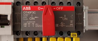
Connecting the generator to a changeover switch
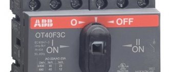
Connecting the generator via an ABB switch
To organize the coupling, you will need two modular contacts or an electrical switch for 7 contacts. A pair of them should be normally closed, and a pair should be normally open. The connection is made like this:
- It is required to enter the extreme contact of the switch to enter the line and cable of the station.
- The middle contact is brought to the consumer.
- The switch is placed in its original position - connected to the main network.
- During the switching process, power is supplied from the generator.
- The switch is installed in the control panel.
- To warm up the system and supply power after activating the generator, a time relay is installed.
- The backup contactor is energized through the main input communicator via a normally closed contact.
Switching processes are implemented by the user. It sets the switch to neutral mode in case of voltage drop. When it resumes, the first contact is activated, opening the power circuit of the second input.
Switching method
To move from one switch state to another, some physical action must be performed that causes the physical state of the component to change. The way the switch is activated is one of its most distinctive features. The simplest distinction can be made at the boundary between switches that are activated by humans and switches that use other forces or phenomena to change their position. Activation of the switch can be done by sliding, pressing, pulling, rotating, or any other action, most commonly using your hand/fingers. But there are also foot-activated buttons on the market, or special elements activated, for example, by the elbow - even pressed with the tongue, designed for people with disabilities.
Switching elements that use physical phenomena other than human movement can be activated, for example, by temperature (thermostats), pressure (pressure switches), magnetic field (reed switches) and so on. They are most often used as safety or control elements in control systems. Although the mechanical characteristics of these types of components are completely different from human-activated switches, they are described by the same electrical parameters as other switches.
Scope of application
Voltammeter
Mainly, the phase switch is used to connect a backup power line, which, in turn, guarantees the uninterrupted operation of the equipment. Switching to the backup power line is automatically performed only at the moment if one of the transformer phases is overloaded.
The use of a phase switch in offices and in production is used to ensure the operation of automated systems, monitoring and control equipment, dispatch equipment, communications, and ventilation systems.
In medicine, an automatic phase switch is used to operate equipment such as life support devices, walking units for storing medicines.
In addition, the phase switch is used for the constant operation of equipment used in private houses and apartments for uninterrupted operation:
- gas boilers;
- security systems;
- modern home control systems;
- video surveillance.
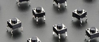
Stable and unstable button
All switches fall into one of two categories: momentary (monostable) or fixed (bistable). A momentary (monostable) button is a switch that does not have a stable closing position (although there are also switches that are closed by default). This means that the circuit is completed only momentarily while the operator operates the switch in some way, then that switch returns to its default state. Most switches, called pushbuttons, are classified as momentary switches.
There are snap-on switches (stable) buttons, but they, in fact, represent a narrow group of these elements, therefore, when we usually talk about buttons, we mean a momentary button.
On the other hand, toggle switches behave the same way as light switches on the wall - they remain in one state until they switch to another, in which they then remain until the action is performed again.
Re- or breaker
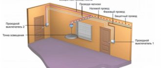
Difference between a pass-through switch and a switch
To make the final choice, you should develop an initial wiring plan or study an existing one. It is usually attached to the technical documentation of the apartment or building. Then you need to determine the longest sections or rooms (workshops, corridors), imagine possible situations based on personal preferences (such as in the bedroom).
If you need to control one light source from different sides, you should install a switch. Then select the type of device - pass-through and cross-over switch. The first allows you to turn off the lamp from two different points, the second - from three or more. To install the latter type and route the wires correctly, it is better to invite a professional electrician.
When connecting several switches at different points in an apartment or room, you should keep a wiring connection plan. Otherwise, if repairs or redevelopment are required, it will be difficult to install all contact options for sockets and other elements.
Can a switch be used as a switch
During use, different situations arise. For example, after purchasing an apartment, it turned out that the previous owners installed switches in several rooms, and now their functioning is no longer needed.
To redirect the action of the device, it is enough not to use the third contact, which diverts the flow of electricity in another direction. First of all, the complete circuit of the electrical network closed by this switch is determined. The non-essential contacts are then isolated. After this, the mechanism will stop redirecting the current and will begin to work like a regular switch.
Switch poles and positions
The switch must have at least two contacts - one acts as a normal input, the other as a normal output, but this only applies to the simplest version of the switch. Most often the switch has more than two contacts. There are generally many different switch configurations, which are described by the number of circuits and the position.
- The number of poles in a switch determines the number of individual circuits it can control. A single-pole switch can control only one circuit, but a four-pole switch can control four different circuits at the same time.
- The number of switch positions determines how many contacts each pole of the switch can be connected to. For example, if a switch has two positions, each circuit (pole) in the switch may be connected to one of the two contacts.
Knowing how many poles and positions a switch has, you can more accurately classify it and present its circuit diagram (and vice versa). Typically switches fall into one of the following categories:
- single-pole single-circuit - SPST ,
- single-pole double-circuit - SPDT ,
- two-pole double-circuit - DPDT .
Of course, there are switches with a large number of poles and switched circuits.
Principle of operation
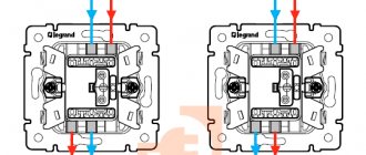
Since 2-position electrical pass-through switches have one more contact compared to classic switches, the connection diagram for these devices is somewhat more complicated. When you press a key, one circuit is closed, and the second is opened at that moment. Thus, the device does not have an “off” position, but is designed for two operating states:
- Connecting the input to output No. 1.
- The input is connected to output No. 2.
On the body of branded devices there is a diagram of its connection, which simplifies the task. If you purchased a cheap product, then most often you have to call the contacts. This should definitely be done, as some unscrupulous manufacturers often confuse the contacts during assembly, and the switch will not work normally.
Contacts are called using a digital or dial device. In the first case, when the terminals are closed, a sound signal will sound, and in the second case, the arrow will deflect to the right all the way. These manipulations are necessary in order to detect common contact.
SPST switches
A single-pole, single-circuit SPST switch has one input and one output, and can be closed or open by default. It is used as switches or momentary buttons on a keyboard. The SPST rocker switch and its circuit diagram are shown in the figure below.
Features of using a three-position switch
Three-position changeover switch
A three-pole switch is suitable for connecting backup power to a home line. It is used only after the load has been disconnected. The generator will need to be activated and set to working position. Then you need to connect your home network to it. When carrying out repair work, the switch will be used as a disconnector.
Device installation
Changeover electrical equipment is installed in the switchboard. Models with a plastic case are suitable for indoor installation, and metal ones for external installation. Inside the boxes there is a special DIN rail for switches. Installation of devices is carried out as follows:
- Models that switch off under load are installed vertically.
- The type of tires and wires is selected. Their cross section must correspond to the current rating of the switches.
- Buses and wires are connected to fixed contacts.
- The elements are tightly clamped with terminals to ensure reliable contacts and eliminate the possibility of overheating.
- The threads of the nuts are coated with Vaseline.
- Contact nuts tighten smoothly. After the first turn of the wrench, the nut is loosened and then carefully tightened.
- Castor oil is applied to the surface of the contact knives, which will prevent them from jamming in the racks.
- Metal non-current-carrying elements are grounded on the outer part of the box.
Switching order
Before connecting, you must stop the input machine
Three-position or package devices are produced without a disconnector. They connect like this:
- Stopping the introductory machine.
- Installing the device handle on the generator line.
- Switching off the load breaker.
- Connecting the switch cable to the generator socket.
- Start the generator, wait for warm-up (2 minutes).
- Supplying power to the switch.
- Turning on the load breakers.
Machines are installed on each of the inputs.
SPDT switches
Another common type of switch is the SPDT, which is a single pole element with two circuits. It has three contacts: one common and two, between which the signal from the common contact is switched. SPDT is ideal for choosing between, for example, two power supplies or two signal sources. It allows you to easily connect one of two circuits to a common element.
The simplest SPDTs are designed as slide switches. The figure shows an example of a slide switch with a schematic diagram of this element.
Operating principle
The principle of operation of a switch To understand what a switch is, you need to consider the principle of its operation and purpose.
The device serves to redirect the flow of electricity to another circuit - one circuit is disconnected and the other is closed at the same time. Therefore, the minimum number of contacts for such a device is three. For mechanisms with two or more “keys” the number doubles. A switch is a switch between electrical conductors of reverse voltage. Purpose – control of one light source from different places. Mainly used for premises with a large area, for example, stadiums, production workshops or warehouses.
DPDT Switches
Double Pole Double Circuit Switch - DPDT is similar to two SPDT switches that can control two separate circuits but are mechanically linked to each other and switch together. The DPDT switch has six contacts. The figure shows a rocker switch with this design and its circuit diagram.
DPDT switches are ideal for switching, for example, balanced signals or any other where it is necessary to switch two lines at once. In addition, such switches are often used to disconnect power from 220 V devices - both lines are turned off simultaneously (phase and neutral wires), since it is usually unknown which line the phase is on.
Connection diagram
After purchasing, you may have difficulty with how to connect the phase switch. If you do not have experience working with electricity, it is better not to try, since you will have to work with high voltage in a three-phase network - 380 Volts. In addition, improper use and connection of such equipment can lead to a short circuit between phases.
The phase switch is a modular device that is installed in a panel on site on a DIN rail. A three-phase circuit breaker is installed in front of it. After installing the primary circuit, we move on to the output circuit. But how to connect the secondary circuits depends on the switch model. The connection diagram must be indicated in the technical data sheet or other similar documentation and may differ from manufacturer to manufacturer.
Finally, we recommend watching a video that explains in more detail what a phase switch is and how to connect it in the panel:
A phase switch is a low-cost method that will increase the stability of the power supply; this can be especially important outside the city in a cottage or holiday village, where there are usually power outages. We talked about how to connect and where to install, as well as all the parameters of such devices. The choice of uninterrupted supply is yours based on your needs and budget.
It will be useful to read:
- How to choose a UPS for your home
- What is a phase control relay
- What is a cam switch used for?
Multi-pole switches
High pole count switches are not very common, but are available in many amazing configurations. They are described similarly to single-pole or double-pole switches/circuit switches, with the first letter (S or D) replaced by a numerical designation. This is how you can imagine, for example, a 4PDT switch that can control four separate circuits with two positions per circuit. An example of such a switch along with the circuit is shown in the figure below.
The situation is similar with switches with a large number of positions. If a four-way switch can be set to one of four positions, for example, it will be designated 4P4T. What will the SP12T switch look like? This could be a rotary switch (bar type), which has 1 pole and 12 positions.
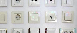
Household use
Using a switch in stairwells
Installing or rewiring electrical wiring is all about functionality and ease of use. Therefore, before installation, a plan is drawn up, which specifies the total number of light bulbs, switches and sockets. Adapter devices are suitable for connection in the following situations:
- multi-level buildings - switches will allow you to turn off the lights on any floor;
- long corridors - you can turn on the lamps at the beginning and turn them off at the end;
- bedrooms - if you install one mechanism at the entrance, and the second near the bed, you will not need to get up to turn off the main light.
Installation and mechanical parameters
The switch can be integrated into the circuit in different ways. The main division in this regard is between panel-mounted and PCB-mounted elements. This is not a strict classification, as there are many switches soldered to printed circuit boards, but intended for panel applications.
Like most electronic components, they can be classified into surface mount components (SMD) or through-hole mount components (THT). Elements for through-hole assembly are usually larger, THT allows higher mechanical loads to be transferred. SMD switches are smaller than their THT counterparts, typically much lower in height, take up less PCB space, and require little force to switch.
Panel-mounted switches are equipped with elements that allow them to be mounted in a housing. They usually have threaded bodies that allow them to be tightened with a nut, but manufacturers also use other solutions. Pins are adapted for THT, SMD or cable assembly.
Environmental resistance
Panel switches are often exposed to the elements. The main threats to these elements are dust and moisture. The IP rating assigned to a switch indicates its resistance to these factors. The degree of protection and IP classes are defined in the IEC 60529 standard.
The IP class is described by two numbers, written in the IPxy format, where x is the first characteristic digit, indicating protection against access to the inside of the housing, as well as protection against dust penetration inside. And y is the second characteristic digit indicating the waterproofness of the switch.
The lowest protection class, IP00, means a device without access protection, in this case a button. The protection class indicates, for example, the size of bodies that can get inside the button, or protection against dust. In the case of protection against ingress of water, the levels of protection vary from droplets of water (level 1) to protection against flooding by a powerful jet of pressurized water (100 bar at 80°C). in accordance with DIN 40050 (class 9). The highest protection class is IP69.
Just as the IP class determines resistance to dust and moisture, the IK class determines the resistance of elements to mechanical damage, the so-called vandal resistance. The IEC 62262 standard defines the mechanical resistance of elements as the amount of mechanical shock energy that a given element can withstand without damage. The standard also specifies the height from which an element can fall without damage or other mechanical testing. The division is divided into classes from IK00 - the element is not at all resistant to mechanical damage, to IK10, where the element can withstand an impact with an energy of up to 20 J (a steel ball weighing 5 kg and with a radius of 50 mm, falling from a height of 40 cm).
Execution and device
According to the degree of protection, a packet switch can be represented by three types of manufacturing:
- Open - for installation in dust-free rooms, in places that prevent accidental contact with current-carrying elements of the device.
- Protected, in which the terminals are covered with a plastic casing that prevents foreign objects from entering the device and prevents electric shock to personnel.
- Hermetically sealed with a plastic casing and rubber seals that prevent moisture from entering.
The basis of the design of any “packet” is one or more fixed contact groups and a switching mechanism. Each fixed section (package) has terminals for connecting electrical wires. The switching contacts are mounted on a movable square-section bushing located inside the device. The bags, alternating with insulating washers, are tightened together with connecting pins. The front and rear sections are closed with covers: at the back - blind, at the front - with a hole for the output shaft of the moving group, on which the control handle is attached.
Electrical parameters of switches
The main electrical parameters of switches are the rated voltage and current, contact resistance and the maximum permissible number of switch movements (switching operations).
- Rated voltage is the maximum voltage that the switch can withstand. This is determined by many factors, including insulating materials, open contact distance, disconnection speed, and safety considerations.
- Forward current rating is the maximum direct current (or alternating current) that a switch can pass through its closed contacts. This current is limited mainly by heating of the switch due to loss of contact resistance.
- Contact resistance is the electrical resistance through which current flows in a closed switch. Because the switch contacts are not a continuous conductor, the contact resistance is greater than that of a comparable continuous conductor. This may cause voltage drops, especially at higher currents.
- The number of operations is the estimated maximum number of switch closures after which electrical and other parameters may deteriorate. Since the switch is a mechanical element, each movement of the switch causes a certain degree of wear on the mechanisms within the element, which leads to deterioration of the switch's performance.
Equipment selection rules
When choosing an automatic phase switch, you should pay attention to the following technical characteristics of the device:
- Acceptable current parameters. This is the most important indicator when choosing a phase switch. You should not choose a model whose current parameters significantly exceed the rating of the input circuit breaker;
- Adjustment functionality. As a rule, on budget models of three-phase switches this functionality is completely absent. This indicates that there is no possibility of adjusting the threshold of the minimum and maximum voltage of the power grid. In addition, in modern models of switches, manufacturers provide a timer, which is configured by the user to attempt to switch to the main phase after a certain time interval;
- Indication and display of operating indicators and device settings. Simple switch models have minimal light indication. More modern devices are equipped not only with a segment indicator, but also with an LCD display, which displays the main parameters of the device settings, the voltage value, and the phase to which the connection is made.
How to make a dimmer for a soldering iron
It often happens that an existing phase switch cannot perform the assigned tasks. This problem can be solved:
- purchasing a phase switch designed for high currents;
- installation of a switch (electromechanical), and it must be connected in such a way that a contactor or coil starter is connected to its output terminals.
Important! It is necessary to carefully study the technical parameters of the equipment. There are big differences not only between household and industrial switches, but also between devices that are similar in scope.
Three-phase distribution board
Keyboards
A keyboard is a matrix of buttons that is most often used to enter data into a device. A common example is the alphanumeric computer keyboard, which, along with a mouse, is used to control the PC. There are many types of keyboards and many technologies used to produce buttons for them. One of the most common types of keyboards is the membrane keyboard.
It consists of thin dielectric and conductive layers glued together. Pressing the field causes the two layers to shorten and join together, thereby completing the button circuit. These types of keyboards, in addition to being compact, are notable for their low price. But this is due to reduced user comfort - a small stroke and, as a rule, the absence of tactile communication worsen the comfort of use. On the other hand, mechanical keyboards that provide noticeable travel provide much greater comfort, but are more expensive and more difficult to manufacture.
Keyboards can be found on many devices, especially those that require data input. The most common are digital keypads, which can be found in electronic locks, intercoms or ATMs. The latter often install keyboards with increased resistance to damage, the so-called anti-vandal protection.
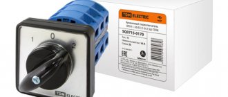
Main types of ACEs
In modern networks in our country, the most common switch models are PF 431 and PF 451. Let us consider them in more detail.
PF 431
This device provides reliable protection of household equipment from voltage surges on phase conductors. It can be installed together with air conditioners, refrigerators and freezers, computers, alarm and video surveillance systems and other equipment that must be continuously supplied with electricity.
The device works according to the following principle. A three-phase voltage is connected to the APF input, and a single-phase network with parameters 220V, 50Hz is connected to the output. The device monitors the output potential difference, and if it goes beyond the established limits, it connects the line to a phase conductor whose parameters correspond to the norm. At the same time, control over the priority conductor, which for this model is L3, does not stop.
When the voltage on it returns to normal, the reverse connection occurs. If the potential difference on L3 is stable, power reconnection to the backup phases will not occur.
PF 451
This device is designed to ensure power stability of single-phase lines. It is used with various household equipment, like the PF 431, and works on a similar principle, which there is no need to describe again. The main difference between them is that the PF 451 does not have a priority phase. Therefore, a line with optimal voltage values is always selected for connection.
Operating principle and installation of an electrical circuit based on a phase switch on video: