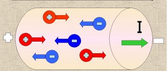
Just as a stationary electric charge acts on another charge through an electric field, an electric current acts on another current through a magnetic field. The effect of a magnetic field on permanent magnets is reduced to its effect on charges moving in the atoms of a substance and creating microscopic circular currents.
What is an electric field?
In physics, this concept is usually understood as a vector field that is formed around particles or bodies with a certain charge. The electric field is considered one of the two integral components of the electromagnetic field.
To better understand the nature of this phenomenon, you need to remember what the Coulomb force is. Coulomb's law serves to determine the degree of interaction between each of a pair of point electric charges. At the same time, it takes into account information about the interval between them.
To understand the tension of the phenomenon, it is worth turning to this example:
- There are 2 bodies that have a charge. In this case, one of them is stationary, and the second moves around the first.
- The Coulomb force in this case is equal to the product of charge and voltage.
- The tension will include the central charge parameter and the square of the distance from the center to the second body.
It is noteworthy that for each point of the electric field the Coulomb force parameter and direction will be different. Due to the difference in directions at different points, the concept is considered vector.
What is a magnetic field?
In physics, this term is understood as a force field that affects exclusively moving bodies, particles or charges.
Each element is characterized by a magnetic moment. The force in this case depends less on the movement of the charge. In this case, electrons act as charged particles. As for the strength of this type of field, the value will be in direct proportion to the speed of the charge and its parameters. The best example is planet Earth. Its central part consists of red-hot iron. Like other metal objects, it can move electrons around it. That is why the largest magnetic field on Earth is formed by the planet itself, or its center, to be more precise. If this field disappears, there is a high probability of disasters and even the death of living organisms.
Expert opinion Ekaterina Vladimirovna Karnaukh Graduated from the National University of Shipbuilding, majoring in Enterprise Economics. A more standard example of such a concept is electromagnets. They typically involve wires that are wrapped around ferromagnets. These elements are a series of substances that acquire magnetic characteristics only if their temperature is below a specific level. The last parameter is called the Cure temperature in physics. In fact, ferromagnets are considered unique elements. They interact with the magnetic field, but do not carry moving charges.
Permanent magnet: interaction with objects, magnetic field, demagnetization
Permanent magnets are substances that have a constant magnetic force. The ends of permanent magnets are called poles. Each magnet has two poles: north (N) and south (S). On some magnets they are marked in two colors (most often blue and red).
Permanent magnets, unlike electromagnets, do not require electricity to create their magnetic field. Permanent magnets are always composed of ferromagnetic materials whose elementary magnets, the atomic spins, are aligned parallel during the magnetization process. This can occur when molten ferromagnetic rocks cool. Such rock (magnetites) was historically found by the ancient Greeks near the city of Magnesia (a city in Asia Minor). Thus, the city of Magnesia is the historical eponym of magnetism.
Small permanent magnets are used to pick up small metal parts or to attach lightweight objects to magnetic boards. For example, some screwdrivers have magnetized tips that allow them to hold a metal screw in a pivot slot. Permanent magnets are also used where it is necessary to create an electric current in small generators using electromagnetic induction. An example of this is a bicycle dynamo.
How do magnets interact with other objects?
Even the ancient Greek scientist Thales of Miletus noticed that objects made of magnetite interact with objects containing iron.
By bringing a magnet close to objects made of various materials, you can establish that very few of them are attracted by the magnet. Cast iron, steel, iron and some alloys are well attracted by magnets; nickel and cobalt are much weaker. In general, bodies made of non-ferrous metals, such as copper, aluminum and others, are not attracted by magnets.
Permanent magnets can attract ferromagnetic substances (such as iron) or repel each other at like poles (north pole to north pole, south pole to south pole). In fact, bodies that retain magnetization for a long time are permanent magnets or simply magnets.
The north pole of a permanent magnet attracts the south pole of another permanent magnet and vice versa. Between the poles of the same name (north pole to north pole, south pole to south pole), on the contrary, repulsive magnetic forces act.
Rice. 1. Permanent magnets
However, permanent magnets can also be obtained artificially. In this process, strong ferromagnetic metals, typically alloys such as samarium-cobalt, are magnetized by a strong external magnetic field. This magnetization process exhibits the so-called hysteresis, that is, the asymmetrical behavior of the material with an increase and subsequent decrease in the external magnetic field. Hysteresis occurs because the alignment of the elementary magnets in a ferromagnet is stabilized by exchange interaction, so a material that has already been magnetized has different properties than a ferromagnet that has not yet been magnetized.
Due to hysteresis, the magnetic field is maintained in the ferromagnet even when the external magnetic field is turned off. Thus, the magnetized material becomes a permanent magnet. The remaining magnetic flux density is called remanent magnetization.
Magnetic field of permanent magnets.
Magnets interact not only with other objects, but also with each other. The space around a magnet in which magnetic forces act is called a magnetic field.
Namely, if you bring the red north pole of a bar magnet closer to the north pole of a second, rotating magnet, then the north pole of this magnet turns away from the north pole of the bar magnet - this works like a force between the two north poles of the magnets, and two identical poles repel each other.
If, on the other hand, you bring the green south pole of a bar magnet closer to the red north pole of a rotating magnet, then the north pole will turn toward the south pole of the bar magnet. There is also a force between two different poles. Two different poles attract each other.
In both cases the following applies: if you remove the bar magnet again, the swing magnet will return to its original position. The following applies: the greater the distance between the poles, the less the force effect and therefore the deflection of the magnet.
Force between magnet poles
Using iron filings you can get an idea of the type of magnetic field of permanent magnets. Figure 2 gives an idea of the magnetic field pattern of a strip magnet. Both the magnetic field lines of an electric current and the magnetic field lines of a magnet are closed lines. Outside the magnet, magnetic lines leave the north pole of the magnet and enter the south pole, closing inside the magnet, just like the magnetic lines of a coil carrying an electric current.
Peryshkin A.V. Physics 8. – M.: Bustard, 2010.
Rice.
2. Experiment with iron filings, which are located according to the magnetic field lines of a strip magnet. What happens if we try to divide one magnet into two? If we repeat the experiments with each of the pieces, we will find that there is a magnetic field around each of them. It turned out that two magnets were created from one magnet. We can never get one magnetic pole. As a result, the magnetic poles in magnets are always arranged in pairs.
Demagnetization.
A permanent magnet can be demagnetized by heat, strong mechanical vibration, or a strong external magnetic field.
While an electromagnet can be turned off by simply turning off the electric current, and the polarity can be reversed by reversing the direction of the electric current, it is not possible to "turn off" a permanent magnet. Hence the term “permanent”.
A permanent magnet remains magnetic until the alignment of the atomic spins is again disrupted by external influences (heat, strong shocks, magnetic fields). Then the magnetic forces disappear, and the material has to be magnetized again. In extreme cases, the material may even be damaged. Therefore, each permanent magnet has a maximum operating temperature. Damage may occur if this temperature is exceeded. Above the Curie temperature characteristic of a particular material, the magnet is in any case completely demagnetized.
Magnetic field strength of a permanent magnet.
The strength of a permanent magnet's magnetic field depends on the material used, as well as the precision with which the material is magnetized. Magnetization leads to high remanent magnetization only if complete alignment of all atomic spins is achieved. This requires suitable materials and technical know-how.
As described by Maxwell's equations, magnetic fields always come from moving charges. There are only magnetic fields caused by the movement of a charge, which always create a magnetic field with a north and south pole.
The magnetic field strengths of permanent magnets are explained by the microscopic movement of charges in matter. For example, electrons in atoms move at tremendous speed. Electrons have a characteristic electron spin. From the general state of electron motion, a magnetic moment arises and, consequently, the strength of the magnetic field.
Magnetic forces always act along the magnetic field. This can be represented by field lines. Field lines also indicate the direction and magnitude of magnetic forces.
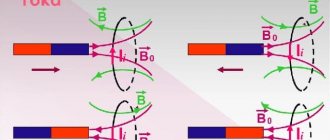
Rice. 3. Magnetic field of a permanent magnet
In Figure 3, you can see that the loop of conductor carrying electric current (left) creates a magnetic field. The magnitude of this magnetic field is measured by the magnetic moment. There are many magnetic moments in a ferromagnetic material (center of the picture). If they are all aligned in parallel, a permanent magnet is created. A permanent magnet has a magnetic field identical to the magnetic field of the coil. In the presented figure, only a few magnetic field lines are schematically indicated.
Permanent magnets can be manufactured in a wide variety of shapes. For example, a horseshoe magnet is shown in Figure 3 on the right. In a horseshoe magnet, the north and south poles are opposite each other. Because magnetic field lines are always closed as a unit, they travel from the north pole to the south pole and then return to the north pole in the material. In the airspace of a horseshoe magnet, this results in a uniform magnetic field with lines of force running parallel between the poles.
What is the difference between an electric field and a magnetic field?
Both concepts under consideration are considered power. This means that at each point in space where the field acts, a specific force affects the charge. At another point its value will be different. The electromagnetic field affects charged bodies and particles. Moreover, it acts on all charges, while the magnetic field acts exclusively on moving ones.
There are substances that interact with a magnetic field, but do not involve moving charges. These include, in particular, ferromagnets. This concept differs from the electric field, since similar substances do not exist for it. Magnets, natural or magnetized bodies, have 2 poles. They are called southern and northern.
Expert opinion Ekaterina Vladimirovna Karnaukh Graduated from the National University of Shipbuilding, majoring in Enterprise Economics. Conventional electric charges are considered relatively homogeneous. They do not include poles. Moreover, such charges are characterized by 2 types - positive and negative. The sign affects the direction of the Coulomb force. As a consequence, this affects the interaction of two charged particles. The sign will not affect the interaction of other charged particles with the magnetic field. It will only reverse the poles.
The graphic representation of the physical phenomena under consideration is also different. Electric field lines have a beginning and an end. They can be visualized. An example is quinine crystals in oil. The induction lines are closed. They can also be visualized. An example of this is metal filings.
Separately, it is worth mentioning the electromagnetic field, which has the characteristics of both an electric and a magnetic field. This means that it is capable, under certain conditions, of turning the compass needle and moving electrically charged particles. Both components have a close relationship with each other. Each of them differs in its energy reserve. It is this that influences the energy of the entire electromagnetic field.
Expert opinion Ekaterina Vladimirovna Karnaukh Graduated from the National University of Shipbuilding, majoring in Enterprise Economics. The emergence of an electromagnetic field is possible with any, even small, change in current in conductors. At the same time, it influences the adjacent zones of space and transfers its own energy to them. As a result, an electromagnetic field also appears in these places.
§17. Magnetic field of a current-carrying conductor and ways to enhance it
Magnetic field of a current-carrying conductor.
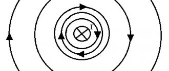
When current passes through a straight conductor, a magnetic field appears around it (Fig. 38). The magnetic lines of force of this field are located in concentric circles, in the center of which there is a current-carrying conductor.
Rice. 38. Magnetic field around a straight conductor carrying current
The direction of the magnetic field around a current-carrying conductor is always in strict accordance with the direction of the current passing through the conductor. The direction of magnetic field lines can be determined using the gimlet rule. It is formulated as follows.
If the translational movement of the gimlet 1 (Fig. 39, a) is combined with the direction of the current 2 in the conductor 3, then the rotation of its handle will indicate the direction of the magnetic field lines 4 around the conductor. For example, if a current passes through a conductor in a direction away from us beyond the plane of a book sheet (Fig. 39, b), then the magnetic field that arises around this conductor is directed clockwise. If the current through the conductor passes in the direction from the plane of the book sheet towards us, then the magnetic field around the conductor is directed counterclockwise.
Rice. 39. Determining the direction of the magnetic field using the gimlet rule.
The greater the current passing through the conductor, the stronger the magnetic field that arises around it. When the direction of the current changes, the magnetic field also changes its direction. As you move away from the conductor, the magnetic field lines are less frequent. Consequently, the magnetic field induction and its strength decrease.
The magnetic field strength in the space surrounding the conductor is
H = I/(2πr) (44)
The maximum voltage Hmax occurs on the outer surface of conductor 1 (Fig. 40). Inside the conductor also
Rice. 40. Distribution curve of magnetic field strength H around and inside a current-carrying conductor.
a magnetic field arises, but its intensity decreases linearly in the direction from the outer surface to the axis (curve 2). The magnetic induction of the field around and inside the conductor changes in the same way as the voltage.
Methods of strengthening magnetic fields.
To obtain strong magnetic fields at low currents, they usually increase the number of current-carrying conductors and make them in the form of a series of turns; such a device is called a winding or coil.
With a conductor bent in the form of a coil (Fig. 41, a), the magnetic fields formed by all sections of this conductor will have the same direction inside the coil. Therefore, the intensity of the magnetic field inside the coil will be greater than around a straight conductor. When the turns are combined into a coil, the magnetic fields created by the individual turns add up (Fig. 41, b) and their lines of force are connected into a common magnetic flux.
Rice. 41. Magnetic fields created by a coil with current (a) and a coil (b)
In this case, the concentration of field lines inside the coil increases, i.e., the magnetic field inside it intensifies. The greater the current passing through the coil, and the more turns there are in it, the stronger the magnetic field created by the coil.
The magnetic field outside the coil also consists of the magnetic fields of individual turns, but the magnetic field lines are not so densely located, as a result of which the intensity of the magnetic field there is not as great as inside the coil. The magnetic field of a coil flowing around current has the same shape as the field of a rectilinear permanent magnet (see Fig. 35, a): magnetic lines of force come out of one end of the coil and enter its other end.
Therefore, a coil flowing around a current is an artificial electric magnet. Typically, a steel core is inserted inside the coil to enhance the magnetic field; such a device is called an electromagnet.
Electromagnets have found extremely wide application in technology. They create the magnetic field necessary for the operation of electrical machines, as well as the electrodynamic forces required. For operation of various electrical measuring instruments and electrical devices.
Electromagnets can have an open or closed magnetic circuit (Fig. 42). The polarity of the end of the electromagnet coil can be determined, like the polarity of a permanent magnet, using a magnetic needle. It turns towards the North Pole with its southern end.
Rice. 42. Electromagnets with an open (a) and closed (b) magnetic circuit
To determine the direction of the magnetic field created by a turn or coil, you can also use the gimlet rule. If you combine the direction of rotation of the handle with the direction of the current in the coil or coil, then the forward movement of the gimlet will indicate the direction of the magnetic field.
The polarity of the electromagnet can also be determined using the right hand. To do this, you need to place your hand with your palm on the coil (Fig. 43) and align four fingers with the direction of the current in it, while the bent thumb will show the direction of the magnetic field.
Rice. 43. Determining the polarity of an electromagnet using the right hand
What is a magnetic field and its properties
Many have seen and held magnets in their hands. It is easy to notice the force that arises between them.
Each magnet has two poles: opposite poles attract, and like poles repel. In addition, magnets are always surrounded by an area where this force occurs. Magnetic fields precisely describe such a force.
Thus, a magnetic field is a concept that is used to describe how force is distributed in the space around and within a magnet. This phenomenon was first noticed by the French scientist Peregrine, and then studied by Ampere and Faraday.
The phenomenon of magnetism and magnetic fields is one of the components of electromagnetic forces, which are basic to nature. A magnetic field appears where charges move. When large charges move at high speeds, the strength of the magnetic field increases.
Magnetic field around a magnet
What is the nature of the magnetic field? There are methods that organize the movement of charges so that they generate such a field. For example:
- You can pass current through a conductor connected to the battery. If the current strength is increased (that is, the number of moving charges is increased), then the magnetic field will increase proportionally. Its strength will decrease in proportion to the distance from the conductor. This phenomenon is called Ampere's law.
- You can use the properties of electrons. They have a negative charge and move around the nucleus of atoms, which is the basis of the operating principle of a permanent magnet. Not all materials can be magnetized. This requires one or more so-called unpaired electrons (usually electrons always form pairs). For example, an iron atom has four unpaired electrons, so this material will make a good magnet.
Every piece of every material is made up of billions of atoms. When they are oriented in space arbitrarily, their field fades, even in the presence of unpaired electrons. Only in stable substances can one obtain a constant orientation of electrons, that is, a permanent magnet or ferromagnet.
Some materials require an external source of magnetic field for this purpose. It is capable of orienting the rotation of electrons and giving them the desired direction, but as soon as the external field disappears, the general orientation will also disappear. Such materials are called paramagnetic materials.
A good example of a paramagnetic material is the metal door of refrigerators. It is not a magnet in itself, but it can attract magnets applied to it. Many people use this property when they use a magnet to attach a shopping list or a note to the refrigerator door.
The experimentally confirmed properties of the magnetic field are as follows:
- it is material, that is, it exists in objective reality, even if we don’t know about it;
- it is generated only by moving electric charges, that is, any moving charged body is surrounded by such a field. Magnetic fields are also created by magnets, but in this case the reason for their appearance lies in the movement of electrons. Alternating electric fields also create them;
- detect these fields by exerting some force on moving electric charges or current-carrying conductors;
- in space its propagation occurs at a speed that is equal to the speed of light in vacuum conditions.
Thus, the magnetic field, which was defined above, is a mysterious and invisible phenomenon, but at the same time completely explainable.
What is magnetic intensity
Iron filings lining up along magnetic fields prove that a magnetic field has two important parameters - magnitude and direction. At any point in space, the magnetic field propagates at a speed equal to the speed of light in a vacuum - 300,000 kilometers/sec.
To define the characteristics of the magnetic field, scientists introduced the value of “tension”. This is a vector quantity indicating the direction of action of the magnetic field and the number of its lines of force. In its characteristics, magnetic field strength is similar to the concept of “force” in mechanics. This indicator does not depend on the parameters of the environment in which the experiments are carried out, but only on the strength of the magnetic flux and the distance to the source producing the field. In various cases, such a source can be a single magnet, a magnetic coil, or an electric wire. In each of these cases, a magnetic field with certain characteristics arises.
How is magnetic field measured?
The magnetic field is a vector quantity and to measure/determine it you need to know its direction and strength.
To determine the direction, you can place a magnetic compass next to a magnetic object. Thus, the compass needle will stop along the field line.
Magnetic field strength is measured:
1. Either in SI units Tesla (T) or microtesla (μT)
2. Either in units of Gauss (G) or milligauss (mG), still used experimentally.
Where:
- 1 T = 10,000 Gauss
- 1 G = T
- 1 mG = 0.1 µT
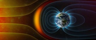
Earth's magnetic field
Our planet has been a huge magnet for several billion years. The induction of the Earth's magnetic field varies depending on the coordinates. At the equator it is approximately 3.1 times 10 to the minus fifth power of Tesla. In addition, there are magnetic anomalies where the value and direction of the field differ significantly from neighboring areas. Some of the largest magnetic anomalies on the planet are the Kursk and Brazilian magnetic anomalies .
The origin of the Earth's magnetic field still remains a mystery to scientists. It is assumed that the source of the field is the liquid metal core of the Earth. The core is moving, which means the molten iron-nickel alloy is moving, and the movement of charged particles is the electric current that generates the magnetic field. The problem is that this theory ( geodynamo ) does not explain how the field is kept stable.
Earth's magnetic field
The Earth is a huge magnetic dipole. The magnetic poles do not coincide with the geographic ones, although they are in close proximity. Moreover, the Earth's magnetic poles move. Their displacement has been recorded since 1885. For example, over the past hundred years, the magnetic pole in the Southern Hemisphere has shifted almost 900 kilometers and is now located in the Southern Ocean. The pole of the Arctic hemisphere is moving through the Arctic Ocean to the East Siberian magnetic anomaly; its movement speed (according to 2004 data) was about 60 kilometers per year. Now there is an acceleration of the movement of the poles - on average, the speed is growing by 3 kilometers per year.
What is the significance of the Earth's magnetic field for us? First of all, the Earth's magnetic field protects the planet from cosmic rays and solar wind. Charged particles from deep space do not fall directly to the ground, but are deflected by a giant magnet and move along its lines of force. Thus, all living things are protected from harmful radiation.
Earth's magnetic field
Over the history of the Earth, several reversals (changes) of magnetic poles have occurred. A pole reversal is when the poles change places. The last time this phenomenon occurred was about 800 thousand years ago, and in total there were more than 400 geomagnetic inversions in the history of the Earth. Some scientists believe that, given the observed acceleration of the movement of the magnetic poles, the next pole inversion should be expected in the next couple of thousand years.
Fortunately, a pole change is not yet expected in our century. This means that you can think about pleasant things and enjoy life in the good old constant field of the Earth, having considered the basic properties and characteristics of the magnetic field.
How is a magnetic field created?
Magnetic fields are created by moving electrically charged particles, i.e. the field appears where electric charges move. For example, passing an electric current through a conductor.
Another way is to combine the electrons' own magnetic fields, which happens in some materials. They are called permanent magnets (for example, the magnets on our refrigerators).
If a very large charge moves at an even higher speed, then the strength of its magnetic field will also increase.
Spin
The electron was discovered to have a magnetic field, the same as it would have if it were a ball rotating around its axis.
This magnetic field was called spin (from English to spin - to rotate). In addition, the electron also has an orbital magnetic moment. After all, the electron not only “rotates”, but moves in an orbit around the nucleus of the atom. And the movement of a charged body generates a magnetic field. Since the electron is negatively charged, the magnetic field caused by its orbital motion will look like this:
If the direction of the magnetic field caused by the electron's orbital motion coincides with the direction of the magnetic field of the electron itself (its spin), these fields add up and are amplified. If these magnetic fields are directed in different directions, they subtract and weaken each other.
In addition, the magnetic fields of other electrons in the atom can be added or subtracted from each other. This explains the presence or absence of magnetism (reaction to an external magnetic field or the presence of its own magnetic field) of some substances.
This article is an excerpt from a book about the basics of chemistry. The book itself is here: sites.google.com/site/kontrudar13/himia
UPD: The material is intended primarily for middle school students. Perhaps Habr is not the place for such things, but where is the place? He is not here.
Characteristics of the magnetic field
Main characteristics:
- magnetic induction
- magnetic flux
- magnetic permeability
Magnetic induction (B)
This is the intensity of the magnetic field. The stronger a magnet or electromagnet creates a magnetic field, the greater the induction.
Formula: B = Ф/S.cos()
Where:
- B - magnetic induction (in T - Tesla)
- Ф - magnetic flux (in Wb - Weber)
- S - surface area (in m²)
- cos - angle (the angle formed between lines B with vector n, perpendicular to plane S)
Magnetic flux (F)
Magnetic induction (B) passes through a certain surface (with area S), and the induction inside it will be listed as magnetic flux (F). Formula: Ф = BS.
This is the total number of magnetic lines of force that penetrate a certain limited surface.
Magnetic permeability
Magnetic induction also depends on the environment where the magnetic field is created. This value is characterized by magnetic permeability. A medium with greater magnetic permeability will create a magnetic field with greater induction.
Magnetic lines and magnetic flux
Magnetic field lines were experimentally discovered around the magnet. These magnetic lines create what is called a magnetic field .
As you may have noticed in the figure, the concentration of magnetic field lines at the very edges of the magnet is much greater than in its middle. This suggests that the magnetic field is stronger precisely at the edges of the magnet, and in its middle it is practically zero. The direction of magnetic field lines is considered to be from north to south .
It is a mistake to believe that magnetic lines of force begin their movement from the north pole and end their life at the south. This is wrong. Magnetic lines are closed and continuous. In a magnet it will look something like this.
If you bring two opposite poles closer, magnets will attract each other.
If we bring the poles of the same name closer, then their repulsion will occur
So, below are the important properties of magnetic field lines.
- Magnetic lines defy gravity.
- They never intersect with each other.
- Always form closed loops.
- They have a certain direction from north to south.
- The greater the concentration of field lines, the stronger the magnetic field.
- A weak concentration of field lines indicates a weak magnetic field.
Magnetic field lines that form a magnetic field are also called magnetic flux .
So, let's look at two pictures and answer the question, where the magnetic flux density be greater? In picture “a” or in picture “b”?
We see that in figure “a” there are few magnetic lines of force, and in figure “b” their concentration is much greater. From this we can conclude that the magnetic flux density in figure “b” is greater than in figure “a”.
In physics, the magnetic flux formula is written as
Where
F - magnetic flux, Weber
B - magnetic flux density, Tesla
a is the angle between the perpendicular n (more often called the normal) and the plane S, in degrees
S is the area through which the magnetic flux passes, m2
What is 1 Weber? One Weber is a magnetic flux that is created by a field of induction of 1 Tesla through an area of 1 m2 located perpendicular to the direction of the magnetic field.
Magnetic field propagation
A magnetic field is one of the forms of manifestation of electromagnetism: a field that affects moving charges, as well as magnetized bodies in different states.
The magnetic field is created by sources in the form:
- conductors through which electric current flows;
- charges and charged bodies in motion;
- bodies that are magnetized;
- variable electrical bodies.
The intensity of the magnetic field is determined using magnetic induction. This value corresponds to the applied force with which it acts on a conductor one meter long with a current flowing through it of 1 A. The unit of measurement of magnetic induction is 1 T (tesla).
Carefully! If a teacher discovers plagiarism in a work, major problems cannot be avoided (including expulsion). If you can’t write it yourself, order it here.
In the formula:
- F – is the greatest force that acts on the conductor;
- L – represents the length of the conductor;
- I – determines the current strength of charged particles in the metal.
Image of magnetic fields
A magnetic field can be depicted on a sheet of paper using lines of force. They are drawn in such a way that the real direction of the field forces at each point coincides with those drawn. The directions of force fields can be determined using a compass needle, the north pole of which is always tangent to the field line. The North Pole is usually designated as the place from which magnetic field lines emerge, and the South Pole as the place where they enter. It should be remembered that such a division is very arbitrary and is taken into account only because of its clarity.
An empirical method for finding the speed of electromagnetic waves
The speed at which electromagnetic waves travel can be determined empirically. At the same time, stationary waves obtained in the circuit are studied. For example, such a picture can be observed when the output of the generator is connected to the line wires through capacitors. During operation of the generator, voltage fluctuations occur between the wires, which indicates the presence of electric field fluctuations. This creates an electromagnetic wave.
You can understand the intensity of vibrations at different points of the line if you turn on incandescent lamps. Thanks to such an experiment, it is possible to find out that the occurrence of standing waves in a line is caused by a certain frequency of the generator, which coincides with the natural frequency of the lines.
By measuring the distance (△x) at which neighboring nodes in a standing wave are removed, we can conclude that this value is equal to 1/2 the wavelength (λ). If you measure ν, that is, the oscillation frequency of the generator, then you can determine the speed of propagation of the electromagnetic wave using the formula:
V = λ * v
Oersted's experience
The most important experimental proof that a magnetic field arises due to the movement of charges is Oersted's experiment. In 1820, Oersted experimentally connected electricity and magnetism through an experiment with the deflection of a compass needle.
This phenomenon was used when the first ammeters were created, since the deflection of the needle is proportional to the magnitude of the current. It underlies any electromagnet.
And here is a video of the experiment:
What is a uniform and inhomogeneous magnetic field
A uniform magnetic field is a magnetic field at any point of which the force on the magnetic needle is the same in magnitude and direction.
In a uniform magnetic field, a charged particle moving with a speed \(\overrightarrow v\) perpendicular to the induction lines is exposed to a force \(\overrightarrow{F_л}\), constant in magnitude and directed perpendicular to the velocity vector \(\overrightarrow v\). In such a field, magnetic induction B at all points is the same in magnitude and direction.
Thanks to the Lorentz force in a uniform field, particles move uniformly in a circle with centripetal acceleration.
Carefully! If a teacher discovers plagiarism in a work, major problems cannot be avoided (including expulsion). If you can’t write it yourself, order it here.
The Lorentz force \(\overrightarrow{F_л}\) is an electromagnetic force from a magnetic field acting on a moving charge q:
\(F=qE+q\left[vB\right]\)
The invariance in absolute value of the centripetal acceleration of a particle moving with a constant velocity in absolute value means that the particle moves uniformly in a circle with radius r.
The radius r of a circle is defined as the quotient of the product of mass m with speed v and the product of electric charge q with induction B.
The radius of the trajectory of a particle with a constant mass and its speed do not affect the period of its revolution in a uniform field.
In a uniform magnetic field, the maximum torque \(M_{max}\) under the influence of closed conductors made of very thin wire of different sizes and shapes with current acquires the following properties:
- It is proportional to the current in circuit I.
- Proportional to the area of the contour.
- For contours with the same area does not depend on their shape.
Thus, the maximum torque becomes proportional to the magnetic moment \(P_{m}\) of the current-carrying circuit:
\(P_m=I\ast S.\)
The magnitude of the magnetic moment \(P_{m}\) characterizes the effect of the magnetic field on a flat circuit with current.
In this case, the value of the torque \(M_{max}\) acting on the circuit with the magnetic moment \(P_{m}\) is taken equal to unity.
Consequently, the formula for determining the induction B in a uniform magnetic field takes the form:
\(B=\frac{M_{max}}{P_m}.\)
Examples of uniform magnetic fields:
- Magnetic field inside the solenoid. A solenoid is a long cylindrical coil consisting of several turns of wire tightly wound in a spiral staircase. Each turn creates its own magnetic field, which adds up with others into a common field. It is uniform provided that the length of the coil significantly exceeds its diameter. Then inside the solenoid the field lines will be parallel to its axis and straight.
- Magnetic field inside a toroidal coil. Here the lines are closed inside the coil itself. Presented in the form of circles parallel to the torus axis. Currents in the winding of a toroidal coil flow uniformly clockwise.
A non-uniform magnetic field is a magnetic field in which the force acting on a magnetic needle placed in this field at different points of the field can be different both in magnitude and in direction.
In a non-uniform magnetic field, magnetic induction in different places has different magnitudes and directions. To calculate the value of the vector \(\overrightarrow B\) in a non-uniform field, it is necessary to determine the torque acting on it. To do this, a contour of dimensions smaller than the distances at which the field changes noticeably is placed at a certain point.
Examples of non-uniform magnetic fields:
- Outside the solenoid. The lines at the ends of the solenoid coil are not parallel to each other and extend from one end to the other. And outside, near the side surface of the coil, the field is practically absent.
- Outside the strip magnet. The magnetic field of a bar magnet is similar to the field around a solenoid. Magnetic lines stretch from one end of a magnet to the other in the direction from the north pole to the south pole. There is a neutral zone.
Differences between homogeneous and inhomogeneous magnetic fields
- A uniform field is inside a conductor or magnet, a non-uniform field is outside.
- In a uniform field, the force acting at different points is the same. In heterogeneous - different.
- The lines of a uniform magnetic field are equal in density and parallel to each other. In a non-uniform field, the lines differ in density and are curved.
- The lines of magnetic induction of a uniform field are at an equal distance from each other.
Circulation of the magnetic induction vector
To calculate the magnetic induction of simple magnetic fields, the Biot-Savart-Laplace law is sufficient. However, with more complex magnetic fields, for example, the magnetic field of a solenoid or toroid, the number of calculations and the cumbersomeness of the formulas will increase significantly. To simplify calculations, the concept of circulation of the magnetic induction vector is introduced.
Circulation of the magnetic induction vector along an arbitrary contour.
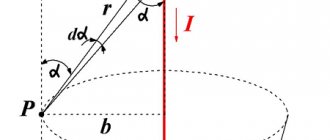
's imagine some circuit l , which is perpendicular to the current I. At any point P of a given circuit, the magnetic induction B is directed tangentially to the given circuit. Then the product of vectors dl and B is described by the following expression
Since the angle dφ is quite small, the vector dlB is defined as the length of the arc
Thus, knowing the magnetic induction of a straight conductor at a given point, we can derive an expression for the circulation of the magnetic induction vector
Now it remains to integrate the resulting expression over the entire length of the contour
In our case, the magnetic induction vector circulates around one current, but in the case of several currents, the expression for the circulation of magnetic induction turns into the law of total current, which states:
The circulation of the magnetic induction vector in a closed loop is proportional to the algebraic sum of the currents that the given loop covers.
What are power lines and how are they located?
Magnetic field lines or magnetic induction lines are lines whose tangents at each point have the direction of the induction vector at that point. These lines are similar to the lines of the electrostatic field strength vector.
If we imagine that there is a small magnetic needle at a certain point in the magnetic field, then under its action it will be positioned tangent to the field line at this point. The northern end of the arrow will indicate the direction of the magnetic field line.
Note: Magnetic induction lines always have neither beginning nor end, that is, they are always closed. Magnetic lines correspond to the direction of the vector at each point of the field. Vector directions are indicated by arrows.
Fields with closed vector lines are called vortex fields.
In a uniform magnetic field, all lines are parallel and equal to each other.
In a straight conductor, the magnetic induction lines are located in the form of circles lying in planes perpendicular to the conductor. The centers of the circles are on the axis of the conductor.
In order to determine the induction vector in this case, it is necessary to look along the conductor in the direction of movement of positive charges, that is, in the direction of the current. The magnetic induction vector will be directed clockwise. If the current is directed towards the observer, then the induction vector is directed counterclockwise.
Model of the magnetic field of a moving charge
To remember the direction of the magnetic field of a moving positive charge, we will imagine ourselves in its place.
Raise your right hand up, then point it to the right, then lower it down, then point it to the left and return the hand to its original position - up. Then we repeat this movement. Our hand makes circles clockwise. Now let's start moving forward, continuing to rotate our hand. The movement of our body is an analogue of the movement of a positive charge, and the rotation of our hand clockwise is an analogue of the magnetic field of a charge. Now imagine that around us there is a thin and strong elastic web, similar to the strings of space that we drew when creating a model of the electric field.
When we move through this three-dimensional “web”, due to the rotation of the hand, it, deformed, moves clockwise, forming a kind of spiral, as if wound in a coil around a charge. Behind us, the “web” is restoring its correct structure. This is roughly how you can imagine the magnetic field of a positive charge moving straight.
Now try to move not straight forward, but in a circle, for example, turning left while walking, while rotating your hand clockwise. Imagine that you are moving through something that resembles jelly. Due to the rotation of your hand, inside the circle you are moving in, the “jelly” will move upward, forming a hump above the center of the circle. And under the center of the circle, a depression is formed due to the fact that part of the jelly has shifted upward. This is how you can imagine the formation of the north (hump on top) and south (hollow on the bottom) poles when a charge moves around the ring or rotates.
If you turn right while walking, a “hump” (north pole) will form at the bottom.
Similarly, one can form an idea of the magnetic field of a moving negative charge. You just need to rotate your hand in the opposite direction - counterclockwise. Accordingly, the magnetic field will be directed in the opposite direction. Just watch each time in which direction your hand pushes the “jelly”.
This model clearly demonstrates why the north pole of one magnet is attracted to the south pole of another magnet: the “hump” of one magnet is pulled into the “hollow” of the second magnet.
And this model also shows why there are no separate north and south poles of magnets, no matter how we cut them - the magnetic field is a vortex (closed) “deformation of space” around the trajectory of a moving charge.
Magnetic field detection methods
Scheme of experiment for magnetic field detection:
- Fasten two flexible conductors parallel and vertically. For experiment, you can take conductors consisting of wire of various thicknesses and made of different types of metal. You can use steel, copper, aluminum, nichrome wire.
- Connect the poles of the current sources to their lower ends. In this case, the conductors should not repel or approach each other, since Coulomb forces do not appear when the potential difference between the charges of the conductors is insignificant.
- It is necessary to connect the conductors so that an electric current flows through them.
- In the first option, it is necessary to short-circuit the ends of the conductors so that currents of the opposite direction arise in them. The conductors must repel each other.
- In the second option, it is necessary to short-circuit the ends of the conductors to create currents in one direction. They should be attracted to each other.
Experience allows us to detect magnetic interaction, that is, the interaction between electric charges moving in a direction.
A magnetic field can be detected by its effect on electric current, that is, by its effect on moving charges.
Experiment to determine the nature of the action of a magnetic field on a current-carrying circuit:
- Hang a small flat frame consisting of several turns of wire on thin flexible conductors woven together.
- Place the wire vertically at a significantly greater distance than the dimensions of the frame.
- The frame must be positioned so that when electric current is passed through it, the wire ends up in the plane of the frame.
- When changing the direction of the current, the frame must rotate 180⁰.
Experience shows that a magnetic field is created not only by currents in conductors, but also by any directional movement of electric charges.
A magnetic field can be detected by the deflection of a nearby magnetic needle on a compass when an electric current is passed through a conductor.
The magnetic field is also created by permanent magnets. To detect it, it is necessary to suspend a flat frame with current on flexible conductors between the poles of the magnet. The frame must be rotated until its plane becomes perpendicular to the line connecting the poles of the magnet. Experiments make it possible to see the orienting effect of a magnetic field on a current-carrying frame.
Two fields
- An electric field is formed around any bodies or particles that have a certain amount of electric charge. If certain changes in the parameters of the magnetic field occur, this process is accompanied by the movement of electromagnetic waves. For clarity, in the diagrams such fields are depicted in the form of lines of force (dotted lines), which begin at positively charged particles and end with arrows touching negatively charged particles. It is the charges here that are the basis for the existence of the electric field.
In the process of conducting research and for the purpose of more effective practical application of this phenomenon, it was given the name tension. It is assessed by the degree of impact on a single (positive sign) charge.
- The magnetic field has a different type of effect, primarily on various electrical bodies and charges that are in motion. Magnetic moments are taken into account without determining the actual magnitude of the movement, and the field itself is created during the passage of a current of charged particles. The field strength is the sum of the magnetic moments of electrons located inside atoms or other particles.
The method of graphical representation using dotted power lines is also used here. But unlike the schematic representation of the electric field, these lines are closed along a contour and do not have a specific starting point (as well as an end).
Magnetic flux
Before you understand what electromagnetic induction is, you need to define such an entity as magnetic flux.
Imagine that you took a hoop in your hands and went outside into the rain. The heavier the rain, the more water will pass through this hoop - the greater the flow of water.
If the hoop is positioned horizontally, a lot of water will pass through it. And if you start to turn it, it’s already smaller, because it is not located at a right angle to the vertical.
Now let's place the hoop vertically - not a single drop will pass through it (unless the wind blows, of course).
Magnetic flux is essentially the same flow of water through a hoop, only we count the magnitude of the magnetic field passed through the area, not the rain.
Magnetic flux through the area S of the circuit is a scalar physical quantity equal to the product of the magnitude of the magnetic induction vector B, the surface area S penetrated by this flux, and the cosine of the angle α between the direction of the magnetic induction vector and the normal vector (perpendicular to plane of a given surface):
| Magnetic flux Ф - magnetic flux [Wb] B—magnetic induction [T] S - area of the penetrated surface [m^2] n — normal vector (perpendicular to the surface) [-] |
Magnetic flux can be visualized as a value proportional to the number of magnetic lines passing through a given area.
Depending on the angle α, the magnetic flux can be positive (α < 90°) or negative (α > 90°). If α = 90°, then the magnetic flux is 0. This depends on the magnitude of the cosine of the angle.
You can change the magnetic flux by changing the area of the circuit, the field induction module, or the location of the circuit in the magnetic field (by rotating it).
In the case of a non-uniform magnetic field and a non-flat contour, the magnetic flux is found as the sum of the magnetic fluxes penetrating the area of each of the sections into which a given surface can be divided
Lecture on physics on the topic “Magnetic field”
Topic: Magnetic field
Purpose: To study magnets and their interaction. A magnetic field. Magnetic field of current. The effect of a magnetic field on a current-carrying conductor. Ampere power. Interaction of currents
As
a result of studying the topic, you should:
– know what the phenomenon of magnetism is, how like and unlike magnetic poles interact;
– know what a magnetic field is and how it is graphically depicted;
– know what quantity is called magnetic field induction and in what units it is measured;
– be able to determine the direction of the lines of force and the induction vector of the direct current magnetic field using the rule of the right screw or the right hand;
– know what force is called the Ampere force, what formula it is expressed by;
– know the formula for calculating the force of interaction of two long parallel conductors with current;
– be able to determine the direction of the Ampere force using the left-hand rule;
– be able to determine the directions of forces of interaction of straight long conductors with current;
– be able to solve simple problems using the formulas provided in the paragraph.
Magnets and their interaction. A magnetic field. Magnetic field of current. The effect of a magnetic field on a current-carrying conductor. Ampere power. Interaction of currents.
- Magnets and their interaction. A magnetic field. Magnetic field of current
Magnetism is the property of the mineral “magnetite” (31%
FeO + 69% Fe 2 O ) to attract iron objects.
The name of the mineral comes from the name of the area Magnesia, where it was mined.
A magnet, made in the form of a rod, is oriented with one end to the north pole of the Earth, and the other to the south (compass needle). These ends were called respectively: the NORTH POLE OF THE MAGNET and the SOUTH POLE OF THE MAGNET.
Magnets interact with each other, being attracted by opposite poles (Fig. 31.1).
Rice. 31.1. Interaction of magnet poles:
A
) repulsion of poles of the same name;
b
a) b)
) attraction of opposite poles.
Magnetic interaction is transmitted through a magnetic field.
The magnetic field can be seen by placing small iron filings around a magnet. The lines that form iron filings or magnetic arrows around a magnet are called MAGNETIC FIELD LINES (Fig. 31.2).
We agreed to assume that the lines of force come out of the north pole of the magnet and enter the south.
Rice. 31.2. Magnetic field of a permanent magnet: a) iron filings in the field of a permanent magnet; b) magnetic needles in the field of a permanent magnet
A
)
b
)
Electric current creates a magnetic field around itself. It, like the field of a permanent magnet, can be detected using magnetic needles or iron filings (Fig. 31.3).
Rice. 31.3. Magnetic action of a conductor with current in a perpendicular plane: a) on iron filings; b) on magnetic needles
N
Fig.31.4. Gimlet and right hand rules.
The direction of the magnetic field lines is determined using the gimlet rule (right screw) (Fig. 31.4-
a
) or the right hand rule (Fig. 31.4-
b
).
The magnetic field is characterized by a value called “INDUCTION”. This is a vector quantity
.
The magnetic induction vector is directed tangentially to the magnetic field lines
(Fig. 31.5
)
.
Induction is denoted by . The unit of induction is called tesla: 1 Tesla.
- The effect of a magnetic field on a current-carrying conductor. Ampere power
A magnetic field interacts with an electric current.
The force with which a magnetic field acts on a piece of conductor carrying current is called the Ampere force.
It is equal to the product of the current strength, the magnitude of the magnetic induction and the length of the conductor segment, by the sine of the angle between the directions of the current and the magnetic induction vector:
If the direction of the current and the direction of the lines of force are perpendicular, the formula takes the form: The direction of the Ampere force is found using the left hand rule: left hand positioned so that the magnetic field lines enter the palm, and four fingers show the direction of the current;
then the extended thumb will show the direction of the Ampere force (Fig. 31.6).
A
)
b
)
V
)
Rice. 31.6. Ampere force acting on a current-carrying conductor in a magnetic field:
A
)
α
= 0;
b
) arbitrary angle
α
;
c
)
α
= 90º.
- Interaction of currents
Electric currents interact with their magnetic fields. Currents of the same direction attract. Currents in opposite directions repel each other (Fig. 31.7).
Ampere's experiments showed that segments Δ l
of infinitely long parallel conductors located at a distance r from each other interact with a force
in this formula coefficient N/m2.
Self-study assignments
1.Read the summary. Learn new terms and wording and answer questions
What is the phenomenon of magnetism?
How do like and unlike poles of magnets interact?
How can you see magnetic field lines?
What is the magnitude of the magnetic field? What is the unit of measurement of this quantity called?
Is magnetic induction a vector or a scalar?
What is the direction of the induction vector relative to the magnetic field lines?
How to determine the direction of the field lines and the induction vector of the direct current magnetic field?
What determines the force of a magnetic field on a current-carrying conductor (Ampere force)? Write and read the formula.
How to determine the direction of the Ampere force?
How are the forces of interaction between two parallel straight conductors carrying current directed?
On what physical quantities does the force of interaction between two parallel long conductors with current depend (write the formula and read it)?
Solve problems
1. What is the work done by the current in an electric motor during 90 s, if at a voltage of 220 V the current in it is 0.2 A?
Solve problems
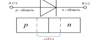
1. In what direction does the force act on conductor A, located perpendicular to the plane of the drawing (Fig. 31.8), if the current in the conductor is directed away from the observer?
2
Rice. 31.9 to problem 2
.Conductor B is placed between the poles of the magnet, as shown in Figure 31.9. The current in the conductor is directed towards the observer. Specify the direction of movement of the conductor.
3. Determine the direction of the magnetic field induction vector if it is known that the current-carrying conductor is deflected to the right under the influence of this field (Fig. 31.10).
4. Determine the poles of the current source if, when the circuit is closed, a force is applied to conductor B in the direction indicated by the arrow (Fig. 31.11).
5. A straight conductor 15 cm long, through which an electric current flows, was placed in a uniform magnetic field with an induction of 0.4 Tesla. The magnetic induction vector is directed perpendicular to the direction of the current. The current in the conductor is 0.6 A. Find the Ampere force.
6*. A straight conductor 10 cm long and weighing 10 g is suspended horizontally in a magnetic field with an induction of 0.1 Tesla. A current of 4.2 A flows through the conductor. The magnetic field induction lines are directed horizontally and perpendicular to the conductor. Make a drawing and find the tension force of the threads on which the conductor is suspended.
The problem has two solutions. Consider both. Refer to paragraph 6.
7
Rice. 31.11 to problem 4
. Find the force of interaction between two parallel pieces of wire 60 cm long, located at a distance of 10 cm from each other, through which currents of 6 A and 8 A flow.
11. A straight conductor 15 cm long is placed in a uniform magnetic field with an induction of 0.4 Tesla, directed perpendicular to the direction of the current. The current in the conductor is 0.6 A. Find the Ampere force. Rep. 0.36 N.
12. A straight conductor 10 cm long and weighing 10 g is suspended horizontally in a magnetic field with an induction of 0.1 Tesla. A current of 4.2 A flows through the conductor. The magnetic field induction lines are directed horizontally and perpendicular to the conductor. Make a drawing and find the tension force of the threads on which the conductor is suspended.
Electromagnetic induction
Electromagnetic induction is the phenomenon of the occurrence of current in a closed conducting circuit when the magnetic flux passing through it changes.
The phenomenon of electromagnetic induction was discovered by M. Faraday.
Michael Faraday conducted a series of experiments that helped discover the phenomenon of electromagnetic induction.
Experience once. Two coils were wound on one non-conducting base: the turns of the first coil were located between the turns of the second. The turns of one coil were closed to a galvanometer, and the second was connected to a current source.
When the key was closed and current flowed through the second coil, a current pulse arose in the first. When the switch was opened, a current pulse was also observed, but the current through the galvanometer flowed in the opposite direction.
Experience two. The first coil was connected to a current source, and the second to a galvanometer. In this case, the second coil moved relative to the first. As the coil approached or moved away, the current was recorded.
Experience three. The coil is closed to the galvanometer, and the magnet moves in (extends) relative to the coil
Here's what these experiments showed:
- Induction current occurs only when the lines of magnetic induction change.
- The direction of the current will be different when the number of lines increases and when they decrease.
- The strength of the induction current depends on the rate of change of the magnetic flux. The field itself may change, or the circuit may move in a non-uniform magnetic field.
Why does induced current occur?
Current in a circuit can exist when external forces act on free charges. The work done by these forces to move a single positive charge along a closed loop is equal to the emf.
This means that when the number of magnetic lines through the surface limited by the contour changes, an emf appears in it, which is called the induced emf.
Law of Electromagnetic Induction
The law of electromagnetic induction (Faraday's law) sounds like this:
The induced emf in a closed loop is equal and opposite in sign to the rate of change of the magnetic flux through the surface bounded by the loop.
Mathematically it can be described by the formula:
Faraday's law
Ɛi — induced emf [V]
ΔФ/Δt — rate of change of magnetic flux [Wb/s]
The “–” sign in the formula allows you to take into account the direction of the induction current. The induced current in a closed circuit is always directed so that the magnetic flux of the field created by this current through the surface bounded by the circuit would reduce those changes in the field that caused the appearance of the induced current.
If the circuit consists of N turns (that is, it is a coil), then the induced emf will be calculated as follows.
Faraday's law for a circuit of N turns
Ɛi — induced emf [V]
ΔФ/Δt — rate of change of magnetic flux [Wb/s]
N - number of turns [-]
The strength of the induction current in a closed conductive circuit with resistance R:
Ohm's law for a conductive circuit
Ɛi — induced emf [V]
I - induction current strength [A]
R - circuit resistance [Ohm]
If a conductor of length l moves with speed v in a constant uniform magnetic field with induction B the emf of electromagnetic induction is equal to:
Induction emf for a moving conductor
Ɛi — induced emf [V]
B—magnetic induction [T]
v—conductor speed [m/s]
l - conductor length [m]
The occurrence of induced emf in a conductor moving in a magnetic field is explained by the action of the Lorentz force on free charges in moving conductors. The Lorentz force plays the role of an external force in this case.
A conductor moving in a magnetic field through which an induced current flows experiences magnetic braking. The total work done by the Lorentz force is zero.
The amount of heat in the circuit is released either due to the work of an external force, which maintains the speed of the conductor unchanged, or due to a decrease in the kinetic energy of the conductor.
A change in the magnetic flux penetrating a closed circuit can occur for two reasons:
- due to movement of the circuit or its parts in a time-constant magnetic field. This is the case when conductors, and with them free charge carriers, move in a magnetic field
- due to changes in time of the magnetic field with a stationary circuit. In this case, the occurrence of induced emf can no longer be explained by the action of the Lorentz force. The phenomenon of electromagnetic induction in stationary conductors, which occurs when the surrounding magnetic field changes, is also described by Faraday's formula
Thus, the phenomena of induction in moving and stationary conductors proceed in the same way, but the physical reason for the occurrence of induction current turns out to be different in these two cases:
- in the case of moving conductors, the induced emf is due to the Lorentz force
- in the case of stationary conductors, the induced emf is a consequence of the action on free charges of the vortex electric field that occurs when the magnetic field changes.
Biot–Savart–Laplace law
As a result of studying the magnetic fields created by electric current, researchers came to the following conclusions:
- magnetic induction created by electric current is proportional to the strength of the current;
- magnetic induction depends on the shape and size of the conductor through which the electric current flows;
- magnetic induction at any point in the magnetic field depends on the location of this point in relation to the current-carrying conductor.
The French scientists Biot and Savard, who came to such conclusions, turned to the great mathematician P. Laplace to generalize and derive the basic law of magnetic induction. He hypothesized that the induction at any point of the magnetic field created by a current-carrying conductor can be represented as the sum of the magnetic inductions of elementary magnetic fields that are created by an elementary section of a current-carrying conductor. This hypothesis became the law of magnetic induction, called the Biot-Savart-Laplace law . To consider this law, let us depict a current-carrying conductor and the magnetic induction it creates
Magnetic induction dB created by an elementary section of a conductor dl.
Then the magnetic induction dB of the elementary magnetic field, which is created by a section of the conductor dl , with current I at an arbitrary point P will be determined by the following expression
where I is the current flowing through the conductor,
r is the radius vector drawn from the conductor element to the magnetic field point,
dl is the minimum conductor element that creates induction dB,
k – proportionality coefficient, depending on the reference system, in SI k = μ0/(4π)
Since it is a cross product, then the final expression for the elementary magnetic induction will look like this
Thus, this expression allows us to find the magnetic induction of the magnetic field, which is created by a conductor with a current of arbitrary shape and size by integrating the right side of the expression
where the symbol l indicates that integration occurs along the entire length of the conductor.
Lenz's rule
To determine the direction of the induced current, you need to use Lenz's rule.
Academically, this rule is as follows: the induced current excited in a closed loop when the magnetic flux changes is always directed in such a way that the magnetic field it creates prevents the change in the magnetic flux causing the induced current.
Let's try a little simpler: the coil in this case is a dissatisfied granny. They take away her magnetic flux - she is unhappy and creates a magnetic field, which this magnetic flux wants to take back.
They give her a magnetic flux, take it, they say, use it, and she’s like, “Why did I give up your magnetic flux!” and creates a magnetic field, which expels this magnetic flux.
"The legislative framework"
The study of fields, magnetic and electric, is carried out according to previously discovered physical laws. Thus, for the electric field, when studying the processes occurring within it, the research and experiments carried out by the pendant provided invaluable assistance. It is easier to imagine the magnetic field using Ampere's law in relation to the location of the human palm. So, in order to determine the direction of the force acting on the conductor, it is necessary to position the palm as follows:
– 4 fingers folded together indicate the direction of the current flow;
– magnetic field lines enter the palm;
– the thumb, located at an angle of 90 degrees relative to the other fingers of the palm, will indicate the direction of the desired force.