September 13, 2017
telecommunications security systems point-of-sale terminalsautomotive electronics asset accountinglighting power managementmotor controlmedicineconsumer electronicsautomationcritical applicationslaboratory instrumentsinternet of thingsLittelfusearticlepassive EC and electromechanicsIndustrial automation
Reed switch is an ultra-precise, high-speed sealed switch controlled by a magnetic field . The number of its operations is up to five billion times. Based on it, magnetic field sensors and reed relays for a wide variety of applications - from household appliances to aviation and astronautics. The article describes the features of choosing reed switches and provides a tabular overview of the wide range of these products produced by Littelfuse .
The word "reed switch" is an abbreviation of the words "sealed contact". The first reed switch was developed in 1936 by the American company Bell Telephone Laboratories. Subsequently, they became widely used as sensors, and reed relays were created on their basis.
Rice. 1. Reed switch
The reed switch (Figure 1) consists of two ferromagnetic conductors with flat contacts sealed in a glass capsule. Without an external magnetic field, the contacts are open and there is a small dielectric gap between them. In a magnetic field, the contacts close. The contact area of both plates has a sputtered or galvanized coating made of a metal that is very resistant to erosion (usually rhodium, iridium or ruthenium). The structure of the contact coating layers is shown in Figures 2a and 2b for rhodium and iridium, respectively.
Iridium, ruthenium and rhodium are very resistant to erosion platinum group metals. Thanks to the deposition of these metals, the number of contact activations reaches five billion times. Nitrogen is usually pumped into the capsule cavity. Some types of reed switches are evacuated to increase the maximum permissible switching voltage. The reed switch contacts in a magnetic field are magnetized, and a magnetomotive force equal to the magnetic field strength arises between them. If the magnetic field strength is high enough to overcome the elastic forces in the contacts that arise during their elastic deformation, then the contacts close. When the field weakens, the contacts open again.
Rice. 2. Structure of contact groups NiFe-W-Ru (a) and NiFe-Au-Ro-Ir (b)
There are two types of reed switches: SPST-NO (Single Pole, Single Throw Normally Open, that is, “one pole, one channel”) - a regular switch in which two contacts are normally open; SPDT-CO (Single Pole, Double Through Change Over, that is, “one pole, two channels - switching”) is a switch in which one contact is always normally closed and the second is normally open.
The reed switch described above and shown in Figure 3 is of the SPST type.
Rice. 3. SPST-type reed switch device
Figure 4 shows an SPDT type reed switch.
Rice. 4. SPDT type three-terminal reed switch device (unipolar bidirectional)
The common plate is the only moving part of such a reed switch; in the absence of a magnetic field, it is closed with a normally closed relay contact. When a magnetic field of appropriate strength occurs, the common plate closes with a normally open contact. Both plates of the normally open and normally closed contacts are stationary. The open contacts have a ferromagnetic coating, and the normally closed contact is made of non-magnetic material. When placed in a magnetic field, the moving contact and the normally open contact are magnetized in the same direction, and with sufficient magnetic field strength, the moving contact closes with the stationary ferromagnetic contact. When the external magnetic field disappears, the magnetization of the contacts weakens and they open. To ensure that the residual magnetization is minimal, high-temperature treatment of the contacts is used in the manufacture of reed switches. A permanent magnet (Figure 5) or a solenoid is most often used as a source of magnetic field for a reed switch.
Rice. 5. Operating principle of a magnetically controlled contact - reed switch
Let's look at several of the most common reed switch-magnet systems.
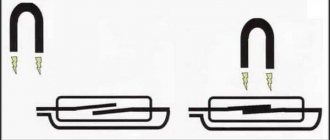
- Approaching and removing the magnet perpendicularly (Figure 6) or at an angle (Figure 7) to the main geometric axis of the reed switch:
Rice. 6. Perpendicular approach and removal of the magnet
Rice. 7. Approaching and moving away the magnet at an angle
In this case, the reed switch will close when the magnet approaches and open when the magnet moves away. Let's take a closer look at Figure 8.
Rice. 8. Reed switch activation zones when the magnet is removed transversely
The concentration of magnetic field lines decreases as the magnet moves away from the reed switch. Magnetic lines are most concentrated at the poles of a magnet. The largest area of interaction between the magnet and the reed switch is in the center of the reed switch. When a permanent magnet is located within this zone, the magnetic field is sufficient for reliable operation of the contact group. The dotted line shows the hysteresis zone - when a magnet enters this zone, the magnetic field does not yet have sufficient intensity to trigger the contact group, but it is enough to keep the contact group in the triggered state. In the case of a different configuration of the reed switch contact group, different from the considered SPST, operation will be understood as the opening of the normally closed contact and the closing of the moving contact with the normally open contact of the SPDT reed switch. Closing of the reed switch contacts can be activated by parallel movement of a ring magnet along the axis of the reed switch, as shown in Figure 9.
Rice. 9. Movement of the ring magnet relative to the reed switch
The configuration of the interaction zones will be similar to the previous system, since the axis of the reed switch and the direction of the magnetic lines of the magnet will coincide with the situation described above, as can be seen in Figure 10.
Fig. 10. Interaction zones when the magnet moves along the axis of the reed switch
- The reed switch can be activated using a flat magnet or a ring magnet with two or 2N poles (Figure 11).
Rice. 11. Activation of the reed switch with a flat or ring magnet
To understand the interaction zones of the reed switch, let's look at Figures 12 and 13.
Rice. 12. The poles of the magnet are perpendicular to the main geometric axis of the reed switch. The magnet moves along it
Rice. 13. The poles of the magnet are perpendicular to the main geometric axis of the reed switch. The magnet moves perpendicular to it
As you can see, the interaction zones are at the ends of the reed switch. In the central part of the reed switch there is a “dead zone” in which the reed switch remains open. Thus, a magnet moving perpendicular to the reed switch, whose poles are located in a similar way, will not activate the reed switch (Figure 14).
Rice. 14. “Dead zone” of interaction between a magnet and a reed switch
- The reed switch can be shielded using magnetic material (for example, steel sheet). Figure 15 shows a stationary reed switch and a stationary magnet between which a shielding object moves.
Rice. 15. Shielding the reed switch with magnetic material
The main types of reed switches produced by Littelfuse are shown in Table 1.
Table 1. Littelfuse reed switch series
| Series | Case length, mm | Load Capacity (Standard: ≤10W, ≤0.5A, ≤200V) | Contact type | Key Features |
| MITI-3V1 | 7 | Standard | SPST | Super-compact (7mm glass body) |
| MDSR-10 | 10 | Standard | SPST | Very compact (10mm glass body) |
| MDSR-7 | 13 | Standard | SPST | Compact (12.7 mm glass body) |
| FLEX-14 | 14 | Standard | SPST | Cheaper, more flexible leads |
| MACD-14 | 14 | Standard | SPST | Small hysteresis |
| MDCG-4 | 15 | Standard | SPST | Low price |
| HA15-2 | 15 | ~240 V (20 W) | SPST | ~ 240 V max. operating voltage |
| MLRR-4 | 15 | 20 W | SPST | Small hysteresis |
| MLRR-3 | 15 | 20 W | SPST | Long leads, increased resource |
| MARR-5 | 19 | 1000 V | SPST | High voltage |
| MRPR-20 | 20 | ~240 V, 50 W | SPST | Switching voltage ~240 V, high power |
| DRR-129 | 50 | 100 W, 3 A, 400 V | SPST | Large, high power |
| MDRR-DT | 15 | Standard | SPDT | Small body |
| DRR-DTH | 40 | 30 W, 0.5 A, 500 V | SPDT | High power |
| DRT-DTH | 40 | 50 W, 1.5 A, 500 V | SPDT | Large, high power |
What is a reed switch
A reed switch is a type of relay. The word "reed switch" is an abbreviation for the words "sealed contact". This is the main feature of this electronic device.
Sealed contact
Conventional electromagnetic relays have movable and fixed metal contacts. There is an air gap between them. When they close or open, an electric arc is formed. The air between the contacts acts as a conductor. Arcing damages the contacts and shortens the life of the relay.
A reed switch works in a similar way, but the terminals are in an inert gas environment. For this reason, arc ignition is not possible. Consequently, the reed relay contacts do not burn out, which increases the service life of the electronic device.
Purpose and scope
Reed sensors, despite being replaced by Hall sensors, still find application in many devices and systems:
- Keyboards for synthesizers and industrial equipment. The design of the sensors eliminates the possibility of sparks. Therefore, they are primarily used in explosive production areas where flammable vapors or dust are present.
- Household meters.
- Automatic security and position control systems.
- Equipment operating under water or in high humidity conditions.
- Telecommunication systems.
- Medical equipment.
Security systems use devices consisting of a reed switch and a magnet. They report the opening or closing of doors. Reed relays are also used, consisting of a contact sensor and a wire winding. This system has some advantages: simplicity, compactness, moisture resistance, absence of moving parts. Reed switches are also used in special areas - these are mechanisms for protecting against overloads and short circuits of high-voltage and radio electrical installations. These are also high-power radars, lasers, radio transmitters and other equipment operating under voltage up to 100 kV.
Part device
The reed switch sensor looks like a small glass tube made of green translucent glass. There are wire leads on both sides. They allow you to solder the part to the board or connect wires to it. There are also three-pin models.
Inside the glass tube there is a cavity with an airless environment. The cavity contains contacts that are connected to the terminals of the device located outside. This part does not have semiconductors. Therefore, it can operate on alternating current.
Reed switches are quite varied in size. Small models have a length of 10-15 mm. The larger ones are the size of a palm.
This is interesting! There is a tendency to reduce the overall dimensions of reed switches. In 2022, the American company put into mass production a part with a tube length of 4.01 mm. In 2005, the Japanese also had achievements in this area and announced the production of a prototype with a flask length of 2 mm. However, these details have not yet received wide distribution.
Basic parameters of memory reed switches
| Reed switch name | MKA-27601 | MKA-2060 |
| Reed switch type | memorizing | memorizing |
| Control pulse power, W | — | 1,2 |
| Control pulse duration, ms | 1,0 | 1,0 |
| Maximum switching power, W | 1,5 | 7,5 |
| Maximum passed current, A | 0,35 | 0,25 |
| Maximum switching voltage, V | 110 | 36 |
| Maximum switching current, A | 0,1 | 0,25 |
| Ambient temperature, °C | -60…+ 70 | -60…+ 125 |
| Vibration loads, frequency range, Hz | 1…600 | 1…3000 |
| Vibration loads, maximum acceleration, m/s2 | 49 | 196 |
| Length and diameter of the cylinder, total length, mm | 27/3/42 | 20/3/42 |
| Reed switch weight, g | 0,6 | 0,5 |
Types of contacts
Reed switches have a classification similar to other types of relays. In terms of contact status, the following models exist:
- With normally closed contacts. If you bring a magnet close, the device's terminals open.
- With normally open contacts. If you bring a magnet close, the terminals will close.
- With changeover contacts. If the magnet is nearby, one group of terminals is closed. If the magnet is removed, the first group will open, but the second will close.
According to the contact arrangement, reed switches are divided into 2 types:
- With dry contacts. Made of solid metal.
- With wetted contacts. There is a drop of mercury inside. It reduces the contact resistance of the device and eliminates contact bounce.
From the point of view of the internal environment, there are 2 types of devices:
- Inside the tube is an inert gas (usually nitrogen).
- A vacuum environment is created inside. This reed switch is used in high voltage circuits, including 220 volts and above.
Vacuum reed switch with mercury
Technical characteristics of high frequency reed switches
| Reed switch name | MKA-10501 | MKA-10701 | MK-17 |
| Reed switch type | high frequency | high frequency | high frequency |
| Magnetomotive force of actuation, A | 30…80 | 16…35 | 18…45 |
| Maximum switching frequency, Hz | 100 | 100 | 2000 |
| Maximum switching power, W | 7,5 | 5 | 2 |
| Maximum switching voltage, V | 80 | 90 | 10 |
| Impedance of electrical contacts (attenuation), Ohm | 0,2 | 0,3 | — |
| Capacitance between contacts, pF | 0,6 | 0,3 | 0,2 |
| Ambient temperature, °C | -60…+ 100 | -60…+ 100 | -60…+ 125 |
| Vibration loads, frequency range, Hz | 2000 | 2000 | 5…3000 |
| Vibration loads, maximum acceleration, m/s2 | 98 | 144 | 196 |
| Length and diameter of the cylinder, mm | 20/3,1 | 10/2,3 | 10/1,8 |
| Total length with leads, mm | 45,6 | 40,75 | 25 |
Operating principle of a reed switch
The contacts are activated under the influence of a magnetic field. Its source is usually a permanent or controlled electric magnet.
The field from the magnet easily penetrates through the glass into the sealed cavity. Once inside, it interacts with the metal contacts of the device.
The magnetic field sets them in motion, thereby closing or opening the electrical circuit connected to the terminals of the part. Therefore, to check the functionality of such a relay, it is enough to bring any magnet to it.
Operating principle of a reed sensor
Closing and opening contacts requires some magnetization time. It is measured in units of milliseconds, so in practice it is usually not taken into account. In most cases, it is acceptable to assume that the reed switch is triggered immediately when it enters a magnetic field.
History of invention
The Soviet scientist of St. Petersburg University V.I. Kovalenko, conducting experiments with a magnetic field in 1922, created magnetically controlled contacts. This invention was registered in the Soviet Union and received patent number 466.
His invention was a core made of a soft magnetic material, to which contacts made of a ferromagnetic material with high magnetic permeability were attached through insulators. After current was applied, a magnetic field arose in the coil, magnetizing the contacts and causing them to close. If the current supply was stopped, the field disappeared, and the contacts became demagnetized and opened.
At that time, the invention did not receive practical application due to the inconvenience of its use and low reliability. In 1936, the reed switch design was improved by engineers from the American company Bell Telephone Laboratories. They proposed placing the working contacts of the device in a hermetically sealed flask. Walter Ellwood was involved in this development, and he eventually created a model of the device. But due to difficulties in manufacturing, the device was again not widely used.
They began to use the device only in 1941, when the American company Western Electric, known for its technical innovations, instead of noisy electromechanical relays in its telephone exchange, did not use a reed switch.
In the mid-60s of the 20th century, the country was massively installed with telephones in the USSR. Based on the findings of the USSR Ministry of Communications, it was decided that a reed switch would be used as switching elements. So, at the plant, located in Leningrad, mass production of devices began. Six years later, magnetically controlled reed switches began to be produced in Ryazan, at a metal-ceramic plant.
At the beginning of 1990, production volume in the USSR reached 230 million units per year, which corresponded to approximately a quarter of the world market. Today, OJSC Ryazan Metal-Ceramic Devices Plant remains the only plant producing such products in the territory of the former Soviet Union. Currently, developments are underway aimed at reducing the size, increasing the speed, sensitivity and stability of reed switches.
Technical parameters of choice
When choosing, you should take into account a number of technical characteristics of this device. The main ones include:
- current switching capacity;
- maximum voltage;
- breakdown voltage of the gap between the contacts;
- contact resistance;
- maximum load power that can be connected to the terminals of the sealed contact;
- time of closing and opening of the device;
- field strength at which the reed switch will operate.
Additional Information! The contact resistance of contacts can increase as they wear out. It also depends on the strength of the magnetic field acting on the reed switch and its position in space.
Parameters of closing reed switches of standard and intermediate types
| Reed switch name | KEM-1 | KEM-6 | MK-36701 | MKA-27101 |
| Reed switch type | standard | standard | intermediate | intermediate |
| Magnetomotive force of actuation, A | 55…110 | 38…50 | 50…80 | 30…60 |
| Response time, ms | 3 | 2 | 2 | 1,5 |
| Maximum switching power, W | 30 | 12 | 21 | 12 |
| Maximum switching voltage, V | 220 | 150 | 100 | 110 |
| Maximum switching current, A | 1 | 0,25 | 0,35 | 0,35 |
| Electric strength, V | 500 | 500 | — | 500 |
| Electrical contact resistance, Ohm | 0,08 | 0,1 | 0,07 | 0,12 |
| Maximum switching frequency, Hz | 100 | 20 | 50 | 100 |
| Ambient temperature, °C | -60…+125 | -60…+125 | -60…+100 | -60…+100 |
| Vibration loads, frequency range, Hz | 1…600 | 1…50 | 1…600 | 1…600 |
| Vibration loads, maximum acceleration, m/s2 | 98 | 98 | 98 | 98 |
| Cylinder diameter, total length, mm | 50/80 | 36/63,5 | 36/63,5 | 27/45,6 |
How to operate a reed switch
Reed switches close (open) contacts when exposed to a magnetic field. The field source is usually a permanent or electric magnet.
If we are talking about a permanent magnet, then the reed switch is in a closed state when the magnet is nearby. If you move it to the side by 5-7 mm, the contacts of the device will open.
With an electric magnet, you don't need to move anything. The reed switch tube is located inside the electromagnet coil. When voltage is applied to it, a magnetic field is generated. It keeps the terminals closed. If the voltage is removed from the electromagnet, the field will disappear and the terminals will open.
Electromagnetic switch with reed switch
Forming and trimming reed switch leads
The length and shape of the axial leads of reed switches are not always convenient for use in a particular device. However, careless modification can significantly affect the performance of the reed switch. When cutting and shaping reed switch leads, it is important to use the correct support and cutting tools to avoid damaging glass-to-metal seals. A damaged case may have either chips that are invisible to the eye or large cracks. Such defects can be detected visually using a microscope with low magnification. But there are cases when the sealing of the housing is broken, and even the method described above for measuring dynamic resistance may not reveal any noticeable deterioration. Over time, moisture will enter the reed switch and its functioning will be impaired.
In order to avoid damage, it is recommended to leave 1 mm of lead length between the forming or cutting point and the reed switch body. In this case, the reed switch terminal must be completely fixed so that mechanical stress during molding or cutting is not transferred to the rest of the terminal.
Let's look at the main methods of molding and cutting reed switch leads.
- Cutting the reed switch leads using side cutters with double-sided sharpening (Figure 28) is unacceptable, since in this case the force deforming the lead will be transferred towards the housing.
Rice. 28. Inadmissibility of cutting reed switch leads with side cutters with double-sided sharpening
Trimming leads with side cutters with one-sided sharpening is permissible (Figure 29), but it must be remembered that the flat side of the side cutter jaws should be on the side of the reed switch body. You should also pay attention to the quality of sharpening and the presence of play in the tool used.
Rice. 29. Trimming reed switch leads with side cutters with one-sided sharpening
- Trimming the leads using a clamp that rigidly fixes the reed switch contacts (Figures 30 and 31).
Rice. 30. Trimming reed switch leads using a clamp (option 1)
Rice. 31. Trimming reed switch leads using a clamp (option 2)
Cutting the reed switch leads with partial fixation (Figure 32) is unacceptable.
Rice. 32. Inadmissibility of cutting the leads of a reed switch with partial fixation
- Forming the reed switch leads without fixing the lead is prohibited (Figure 33), since in this case the part of the lead going into the reed switch body is also subject to deformation.
Rice. 33. Inadmissibility of forming reed switch leads without fixing
Forming the reed switch leads while fixing the lead at two points, as shown in Figure 34, is acceptable, since support B does not allow the lead to deform in the direction from it to the reed switch body.
Rice. 34. Forming reed switch leads when fixing the lead at two points
Forming while fully locking the reed switch lead, as shown in Figures 35 and 36, is also acceptable.
Rice. 35. Forming the reed switch output with full fixation (option 1)
Rice. 36. Forming the reed switch output with full fixation (option 2)
Once the reed switch leads are properly shaped and trimmed, the common configurations shown in Figure 37 can be achieved.
Rice. 37. Common reed switch configurations
Advantages and disadvantages
Like any electronic components, reed switches have advantages and disadvantages. Advantages:
- increased wear resistance;
- compact overall dimensions relative to conventional relays;
- absence of intrinsic noise and signal distortion;
- contacts are isolated from environmental dust.
Flaws:
- inability to work in conditions of extraneous magnetic fields;
- spontaneous opening and sticking of contacts at high currents;
- fragility, vibration intolerance;
- increased contact bounce due to their elasticity.
Operating principle
The operating principle of a reed switch is similar to a switch. The relay consists of a pair of conductive cores with a gap between them. They are hermetically sealed in a glass flask with an inert environment, eliminating the oxidation process.
A control winding powered by direct current is placed around the bulb. When power is applied, the winding generates a magnetic field that acts on the cores and causes the contacts to close together.
When the coil is disconnected from the power supply, the magnetic flux disappears and the contacts are opened by springs. Reliability is ensured by the absence of friction between the contacts, which, in turn, act as a conductor, spring and magnetic circuit.
A special feature of the reed switch sensor is that no forces act on the relay springs at rest. This allows them to make contact in a fraction of a second.
Permanent magnets can also be used. Such devices are called polarized.
Normally closed devices have a different operating principle. Under the influence of electromagnetic force, a system of magnets charges the cores with one potential, causing them to repel each other, opening the circuit.
Switchable reed switches consist of three contacts. One of them is installed permanently and is not magnetic, the other 2 are made of a ferromagnetic alloy. When a magnetic field is induced, a pair of open contacts closes, opening a pair with a non-magnetic contact.
Explanation of markings
On electrical circuit diagrams, the reed switch is designated as a circle with normally open or normally closed contacts. The symbol resembles an ordinary button surrounded by a circle.
In the technical documentation, the reed switch is marked with letters and numbers. For the designations of most such devices, the following is true:
- 1st character – name of the part (MK – magnetically controlled contact);
- 2nd symbol – type of contacts (A – normally open, B – normally closed)
- 3rd symbol – the letter “P” is indicated only on devices with mercury;
- 4th character – length of the flask in millimeters (two-digit number);
- 5th character – functional feature of the device (1 – low and medium power, 2 – high power);
- The 6th character is the serial number of the development.
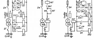
Designation system for reed relays
For example, you can disassemble the MKA-14103 model:
- MK – magnetically controlled contact;
- A – closing;
- the letter “P” is missing, which means without mercury;
- 14 – flask length 14 mm.
- 1 – low or medium power;
- 03 – development order (useless in practice).
Parameters of miniature closing reed switches
| Reed switch name | MUK-MA-1 | KEM-2 | MK-16-3 | MK-10-3 | MKA-10113 |
| Magnetomotive force of actuation, A | 35…90 | 21…64 | 35 | 13…40 | 14…25 |
| Response time, ms | 2 | 1 | 1 | 0,8 | 0,8 |
| Maximum switching power, W | 15 | 7,5 | 0,3 | 3,6 | 1 (VA) |
| Maximum switching voltage, V | 115 | 180 | 30 | 36 | 36 |
| Maximum switching current, A | 0,5 | 0,25 | 0,01 | 0,1 | 0,1 |
| Electrical contact resistance, Ohm | 0,3 | 0,15 | 0,15 | 0,3 | 0,3 |
| Maximum switching frequency, Hz | 100 | 100 | 100 | 10…10 | 100 |
| Ambient temperature, °C | -60…+125 | -60…+125 | -45…+70 | -60…+125 | -60…+125 |
| Vibration loads, frequency range, Hz | 2000 | 1 …2000 | 1…600 | 3000 | 1…3000 |
| Vibration loads, maximum acceleration, m/s2 | 196 | 196 | 49 | 98 | 196 |
| Cylinder diameter, total length, mm | 21,5/40 | 20/46 | 16/- | 10,5/30,5 | 10/42,5 |
Simple examples of everyday use
The reed switch is a simple part, so radio amateurs willingly assemble various devices on it with their own hands. Below are 3 popular solutions that are implemented using this part:
- Signaling. A secret magnet is attached to the door (it is advisable to use neodymium). A door reed switch is installed on the cladding. It is necessary to fasten it so that when the passage is open, the reed switch terminals are open, and when the passage is closed, they are closed. As a result, the door status is converted into an electrical signal. It can also be converted into an alarm sound.
- Homemade on-board computer for a bicycle. In this case, the magnet is installed on the wheel or drive sprocket of the bicycle. The reed switch is fixed on the frame of the “iron horse”. The higher the speed of the bicycle, the more often the magnet comes into close proximity to the part. Using a microcontroller circuit, these pulses can be converted into the current speed of the bicycle or the distance traveled per day can be calculated.
- Use as a limit switch on moving mechanisms (for example, on automatic gates).
Additional Information! The electronics industry also produces reed switches for security alarms. Such amateur-class devices include the wireless door opening sensor ALD01. Professional systems use mortise reed switches, which do not attract attention. They allow you to hide the fact that the detector is operating.
The operating principle of a reed switch is based on its interaction with a magnetic field. If you bring a magnetized object to the reed switch, its terminals will close. And if you place this part in the field of a controlled electric magnet, you will get a relay with increased wear resistance.
This device should be selected based on the maximum permissible current and voltage. At the same time, it is necessary to take into account the operating conditions. Devices such as an electromagnetic intercom lock located near the reed switch can affect its operation.
Reed switch (sealed contact), normally open
I purchased these sensors based on a tip from the comments to one of my previous reviews. By and large, there is nothing to review here, since the principle of their operation is simple, but one of my friends became interested in what it is and how it works - and decided to write this small visual review about this. Principle of operation
Reed switch ( ger
metalized
contact
) is a glass cone, inside of which there are two elastic contact ferromagnetic plates, which, when immersed in a magnetic field, close and a contact is formed, through which current then flows. The flask is usually filled with an inert gas or contains a vacuum. An example of the operation is shown schematically in the animation below, where an ordinary magnet is brought up.
Why do the plates actually close and open due to the presence of a magnetic field? As mentioned above, the plates themselves are ferromagnetic, i.e. they actively attract a magnet to themselves and at the same time they themselves are actively attracted by a magnet. Regular iron has similar properties. A magnet has two polarities - north and south, and the magnetic lines always go from the north pole to the south. When a magnet is brought to the reed switch, magnetic lines will also pass through these elastic plates. In this case, in the figure, the north pole of the magnet is located on the left, the south pole is on the right. Accordingly, the edge of the upper plate becomes south polarity, and the edge of the lower plate becomes north polarity - as a result, the plates are closed. When the magnet moves away, the plates open due to their elasticity. If the magnet is not positioned correctly in relation to these plates, then the magnetic lines will pass through them unevenly, and the contacts will not be able to close.
There are three main types of reed sensors on sale: 1)
Normally open (observable), which are normally open, but when immersed in a magnetic field, the circuit closes.
2)
Normally closed - the opposite principle: in the normal state the contacts are closed, but when immersed in a magnetic field the contacts open.
3)
Reed switches, unlike the first two, already have 3 outputs and 3 plates inside, respectively. In a quiet state, one pair of contacts is closed; when immersed in a magnetic field, the other pair is closed.
Reed switches can also be designed for high current switching or mercury, where the contact points of the plates are moistened with a drop of mercury to suppress contact bounce. The main use of reed switches is in security and automation systems; the simplest example is the automatic triggering of an action when a door or window is opened, for example, sending an alarm signal. Reed relays are made on the basis of reed switches - in high-voltage installations these are used to protect against current overloads, in this case the reed switch is placed in a coil.
Appearance. Dimensions
I took 10 normally open (open) ones. Glass capsule with a slightly greenish tint.
Dimensions correspond to 2×14mm
I assembled a simple circuit with an LED on a breadboard, in the gap of which I placed a reed switch in order to check its operation by bringing a flat neodymium magnet to it, and since the magnetic fields have different poles, the contacts in the reed switch are reliably closed only if the magnet is pointed at it end-to-end and across.
In other positions of the magnet, the contacts in the reed switch will not be closed:
An example with magnets from a motor: turning one side - the contacts close, the other side - no reaction. Therefore, this point is worth taking into account.
How the state of the plates changes - enlarged under a digital microscope
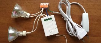
On top of that, it would be nice to show a simple visual test of the operation of this sensor by performing some action when opening and closing a room door, for example, turning on a table lamp using .
First you need to pack the reed switch itself.
A piece of heat shrink is put on and pressed with hot air.
One terminal needs to be bent. But then the first pancake was waiting for me, lumpy - having bent the lead almost at the very base of the cone - the glass broke and the reed switch became unusable:
To prevent this from happening, you need to pinch the terminal 1-2mm from the base of the capsule with tweezers and only then bend it:
The second lead was slightly shortened, along with heat shrink
I solder the wire to both terminals of the wire
Now this whole thing needs to be secured somehow. Therefore, I chopped the glue gun rod into small slices:
I put more heat shrink on the top of the reed switch and stuffed some hot melt glue inside at the base:
Blown hot air
Removed excess glue
The matter remains small. Attach the magnet to the door and the reed switch to the wall opposite the magnet. For a demonstration test, ordinary tape would also work here, fortunately you can quickly remove everything back and forth.
The magnet and the reed switch are located across each other
The electronic-software part is simple: the Pro Mini board is configured for an external interrupt, where the interrupt output through this same reed switch is connected to the board's power supply and while the door is closed and there is a magnet near the reed switch, the circuit is closed, the controller is asleep, and the relays that control the lamp are turned off. As soon as the door opens and the magnet is moved to the side, the reed switch opens, an external interruption occurs, which sends an impulse to the relay and the lamp turns on.
There can be many applications in DIY projects, especially with simple and cheap Attiny13 controllers or, if the project is very simple, with transistors. Due to its small size, the reed switch can be cleverly hidden from prying eyes. I will use them in a new version of the energy-efficient GSM alarm system, although for its full assembly I need to wait for a few more components. Among the disadvantages, I note the fragility of the capsule and vulnerability to other magnetic fields. Regarding reliability, they write that they have a fairly large closing-opening cycle due to the tightness inside the capsule. In general, we'll see.
Uses
Reed relay from TXE-3 telephone exchange
Reed relays
Main article: Reed relay
One or more reed switches inside an electromagnetic coil constitute a reed switch relay. Reed relays are used at relatively low operating currents and provide high speed operation, good performance at very low currents that are unreliably switched by conventional contacts, high reliability and long service life. Millions of reed relays were used in telephone exchanges in the 1970s and 1980s. In particular, they were used for switching in the British TXE family of telephone exchanges. An inert atmosphere around the reed contacts ensures that oxidation does not affect the contact resistance. Mercury-wetted reed switches are sometimes used, especially in high-speed counting circuits.
Magnetic sensors
Reed switches, actuated by magnets, are commonly used in mechanical systems as proximity sensors. Examples are door and window sensors in burglar alarm systems and burglary protection methods. Reed switches have been used in laptops to put the laptop into sleep/hibernation mode when the lid is closed. Speed sensors included on a bicycle wheel often use a reed switch to briefly activate each time a magnet on the wheel passes the sensor. Reed switches were previously used in computer terminal keyboards, where each key had a magnet and a reed switch actuated by pressing the key. Electric and electronic pedal keyboards use organ and Hammond organ players often use reed switches, where the glass contact shell protects them from dirt, dust and other particles. They can also be used to control diving equipment such as flashlights or cameras, which must be covered to prevent high pressure water from entering.
At one time, brushless DC motors used reed switches to determine the position of the rotor relative to the field poles.[3] This allowed switching transistors to function as a switch, but without the contact problems, wear, and electrical noise of a traditional DC switch. The motor design can also be "inverted" by placing permanent magnets on the rotor and switching the field through external fixed coils. This avoided any rubbing contact to supply power to the rotor. Such motors were used in low-power, long-life products such as computer cooling fans and disk drives. As cheap Hall effect sensors became available, they replaced reed switches and increased their service life.
Reed switches are used in at least one brand of endoscopic capsule to turn on the power source only when the unit is removed from the sterile packaging.
Reed switches may be selected for a specific sensor application where the solid state device does not meet requirements such as power consumption or electrical interface compatibility.
Design features of reed sensors
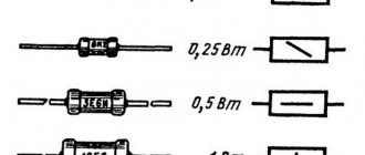
According to their design, reed switches are divided into:
- Open
- Closed
- Switching
- Open mercury
The most common type of reed switch is the open reed switch. Each contact in the glass container is a flat wire. The contact surfaces are plated with gold, palladium, radium or silver, which helps reduce resistance and protects the contacts from corrosion. The space of the glass flask is filled with hydrogen, argon or nitrogen, or simply represents a vacuum space, which also helps to increase the anti-corrosion properties.