RELAY PROTECTION Protection of power lines
Basic concepts. Relay protection (RP) is an important part of automation, with the help of which faults are detected in electrical installations and a signal is sent to turn them off or alert the personnel on duty.
Relay protection is performed using various relays that respond to current, voltage, power or other electrical parameters. Relays with electromagnetic and inductive operating principles, as well as polarized, magnetoelectric and semiconductor relays based on electronic components, have become widespread.
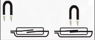
Relays are divided into primary and secondary, direct and indirect. Primary relays are connected directly to the protected circuit (Fig. 23.1, a), secondary relays are connected through current or voltage transformers (Fig. 23.1,6). Direct action relays act directly on the release mechanism of the circuit breaker drive mechanism (Fig. 23.2, a), and an indirect action relay supplies a signal to supply operational current (voltage) to the release coil (Fig. 23.2, b).
The relay protection set consists of triggering elements that directly and constantly monitor the state and operating mode of the protected equipment, and a logical part that selects the relay protection operating mode. Starting elements are current, voltage, power relays, etc.; The logical part mainly consists of time relays, intermediate and indicating relays. In some cases, the starting and logical parts of the relay protection are executed as one whole.
To quickly disconnect a line on which a short circuit has occurred, it is equipped with a relay protection that responds to all types of short circuits and acts to open the circuit breakers. In power supply systems, as a rule, lines operate according to a one-way power supply circuit. To protect them, overcurrent protection, current cutoff and current transverse differential protection of parallel lines are used.
Maximum current protection.
This is the simplest design and therefore the most widespread protection. It is installed at the beginning of the line on the power source side (Fig. 23.3).
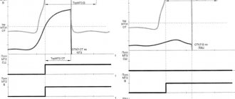
When the current in the line increases above the protection operation current with a time delay t3, a signal is given to trip the circuit breaker (Fig. 23.4).
In electrical networks with ungrounded transformer neutrals, the short-circuit currents are small and the previous scheme is unsuitable for sensitivity conditions. Therefore, special protection is installed in these networks, and more often, instead of it, a special device is provided for monitoring the state of the network insulation in relation to the ground with an effect on the signal (Fig. 23.6,6).
On cable lines, protection against ground faults is carried out using special zero-sequence current transformers. The latter consists of a ring core, put on a three-core cable, and a secondary winding in the form
The greatest difficulty is in setting up differential protection against surges of magnetizing current and unbalance current during external short circuits. The protection perceives magnetizing current surges that occur when the transformer is connected to the network at idle or when the transformer is disconnected from the network as a short circuit in the protected area.
The magnetizing current during the transition period contains a significant aperiodic component, which slowly decays. To tune out magnetizing current surges, a quickly saturating transformer is installed in the protection circuit, which closes the protection in the presence of an aperiodic current component in the differential circuit.
Current cut-off. On low-power transformers, current cutoff is a cheap and effective protection. The protection consists of a current relay, for example, types RT-40, RT-80, which are connected through current transformers on the supply side of the power transformer. The relay operation current is selected so that the protection does not operate in the event of a short circuit behind the transformer;
Gas protection. This protection is installed on transformers of 1000 kVA and more; reacts to all types of damage inside the transformer tank and when oil leaks from the tank.
Gas protection is carried out using special gas relays of the float, vane or cup type, which are installed in the oil line between the transformer tank and the conservator. If there is damage inside the tank under the influence of an electric arc, the oil and insulation decompose, the resulting gases rush into the conservator, which causes the movement of the oil and the action of the gas relay. The gas relay contains two contacts. One of them reacts to slow gas release and sends a signal about a malfunction in the transformer, the other reacts to the intense movement of oil, usually observed during a short circuit, and sends a signal to turn off the transformer.
Maximum current protection. The protection is designed to disconnect the transformer in the event of an external short circuit and is at the same time a backup against internal damage. On a two-winding transformer with one-way power supply, one set of protection is installed on the power source side, which acts to disconnect all switches. Maximum current protection of transformers is carried out by voltage starting, which allows you to build protection against overload currents and increase its sensitivity.
Overload protection. Transformers allow relatively large overloads, so overload protection is carried out with an effect on the signal and consists of a current relay and a time relay. The operating current is selected from the relation
Ground fault protection. One option for such protection is to install a current transformer at the zero of the power transformer (Fig. 23.9). When the transformer windings are short-circuited to ground, current flows in the zero bus 1, and the current relay KA will operate and give a signal to turn off Q1 and Q2. The protection trip current is selected from the condition)
Protection of transformers 6—10—35/0.4—0.23 kV. They are equipped with overcurrent protection, protection against single-phase earth faults on the LV side and gas protection on transformers with a capacity of 400 kVA or more, if they are located indoors.
Protection against single-phase ground faults is carried out by an automatic circuit breaker with an overload release installed on the LV side (Fig. 23.10, a), or by a current transformer on the neutral wire with a solid connection of the transformer on the LV side (Fig. 23.10, b). Gas protection with the effect of its signal on shutdown is shown in Fig. 23.10, at.
In Fig. Figure 23.11 shows transformer protection circuits when installed on the HV side of switches: (Figure 21.11, a, b) - circuit with a direct action relay of the RTM type, which provides overcurrent protection and protection against single-phase ground faults; (Fig. 23.11, c) - protection made with an indirect action relay of the RT-80 type with a dependent characteristic.
Kinds
Relay automation can monitor the following basic parameters of the power line and equipment and, when dangerous values are reached, switches it off:
Maximum current. When the current reaches a certain value, the shutdown relay is activated.
Direction of power. This type of control, in addition to the magnitude of the current, takes into account its direction.
The difference in currents at the input and output of the equipment. It protects generators and transformers by comparing input and output parameters. When dangerous characteristics are reached, consumers are switched off.
Logic devices determine the location of short circuits and allow you to disconnect the dangerous area.
Low and high voltage. In the presence of short circuits, the voltage decreases. An increase in voltage may be caused by a lightning strike. Any change in voltage is dangerous for equipment and electrical networks. When the values change, the automation turns off the line.
Automatic unloading of the line when the frequency of the current in it decreases. When the frequency of the current in the electrical network decreases, the automation switches off some consumers. As the frequency increases, it is necessary to load the network, on the contrary, to reduce the generator speed.
Based on this list of tasks performed, it becomes clear why relay protection is needed. But there are products that do not turn off, but automatically connect consumers. It can be carried out to restart the power supply after a specified time interval or to automatically introduce reserve power. In this case, additional generating capacity is introduced into the network to compensate for the deficit.
Automatic excitation control (AEC)
the process of changing the excitation current of electrical machines according to given conditions. It is carried out on synchronous generators, powerful synchronous motors, synchronous compensators, on generators and DC motors and on other special electrical machines by changing the voltage on the excitation winding. In this case, the strength of the excitation current of the electric machine changes and, as a consequence, the main magnetic flux and emf in the armature windings. ARV of synchronous generators is carried out mainly for the purpose of ensuring a given voltage in the electrical network, as well as to increase the stability of their parallel operation on the general network. ARV is widely used in DC electric drives to maintain a constant speed of rotation of the working part of the machine by influencing the excitation current of the engine or supply generator.
Reliability of LZSh
LZSh, from the point of view of performance testing, differs from other types of protection. It rarely works when tested by employees of measurement laboratories. This is explained by the fact that the LPS is assigned a less significant role; accordingly, it has a longer response time and simply does not have time to get ahead of other types of protection.
Most often, logical bus protection fails due to a short circuit of the current transformer or its turn short circuit. Fortunately, this happens quite rarely. In this case, the transformer is simply not able to correctly measure the current flowing through the bus it controls. Therefore, the LZSh protection blocking signal cannot be generated, which leads to its unintentional activation.
Important! Before disconnecting the wires from the current transformer, its terminals must be shorted together. Otherwise, a high-voltage potential may be induced in the CT winding, which is dangerous to the life of operating personnel and can lead to equipment damage
LPS is a relatively simple and effective system for ensuring uninterrupted operation of the power system. Its use significantly reduces the negative consequences of emergency situations, and also significantly reduces the risk of their occurrence.
What does LZSH consist of?
Answering the question “What is LZSh protection?”, we can say that it includes a complex set of hardware and software designed to disconnect the line during abnormal operation. All of them can be divided into 3 categories:
- Sensors are devices that read information about the state of the power system in real time. For example, current and voltage on power buses, frequency, phase shift and cosph of the load, as well as the temperature of transformers, ambient air and similar indicators. All this information goes to the controller.
- Microprocessor terminals are the computing organ of the system. It would be a stretch to call it a computer. Externally, it is a small box with a screen displaying the network status and many buttons for setting up the device and its interaction with a person.
- Executive bodies - by analogy with a PC, these are peripheral devices. These include high-voltage switches, fans and pumps of cooling systems, and various drives for switching devices.
Simplified, it all works as follows. Some emergency situation occurs on the substation buses, for example, a short circuit. Current transformers register a critical excess of this parameter. From them the signal is transmitted to a microprocessor terminal, which processes it. This takes into account the short circuit current, its duration and a number of other characteristics. Then the terminal sends a signal to the actuator - a vacuum switch, which disconnects the section of the line affected by the short circuit.
Current transformers