Selecting the type of protection
Transformers and autotransformers, in particular, as belonging to one of the subspecies, are reliable and structurally correct from the point of view of the fact that they do not contain rotating and moving parts. This avoids external impacts and chips that would damage the interior.
Also, using the block as the main structural element allows you to avoid movement of parts inside during a change of position or movement. But despite this, during operation it is impossible to completely protect the vehicle from disruption of stable operating conditions and internal damage. To avoid this problem, the equipment is provided with special relay protection.
Also, short phase circuits may occur in the design of the device. In this case, there may be actions between one phase located adjacent to each other, or between one or two to the ground. Problems related to the occurrence of short circuits between windings with different voltages and between turns of the same phase are also common. Short circuits also occur on the surface of busbars, on inputs and cables.
Of course, getting rid of short circuits and protecting against them will potentially protect professionals from injury associated with a current pulse. But, besides this, safety regulations say that protection of transformers is necessary to protect the mechanisms themselves from damage, fire, and surrounding objects from a fire-safe situation that may arise in the event of a breakdown.
The choice of means of protection depends on the existing problems. But in any case, the transformer is equipped with certain casings that are of a primary nature. The remaining means of protection are selected based on the power, design and typology of problems encountered in devices of this type.
Differential protection - operating principle
Fig No. 1. A diagram explaining the principle of operation of differential protection of a transformer, with two-way power supply, a) for a short circuit outside the transformer, at its terminals, b) for an internal short circuit of the transformer
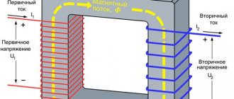
The operating principle of differential protection is based on the application of Kirhoff's first law. The protected object is taken as a node, the current is recorded completely on all branches connecting the object to the external electrical network.
If there is a fault on the outgoing branch, the sum of the currents entering and leaving the node is zero.
If the object is damaged, in the event of a short circuit, the sum of the currents in the branches will be equal to the short circuit currents.
Transformer differential protection differs from differential protection of high-voltage lines and generators by the presence of inequality in the primary currents of different transformer windings and phase mismatch.
Description and scope of differential current protection
Differential protection is the fastest acting for equipment. Thanks to its principle of operation, it has become possible to use it on any device, both those related to the type of conventional power vehicles and cars.
But despite the advantages, the schemes are not universal. They do not occur on all devices, but those that meet the following characteristics:
- single operating devices with power ratings from 6300 kV per A and more;
- functioning transformers arranged in parallel, with power ratings from 400 kVA.
Differential protection is also used if the device power is about thousands of kVA or maybe slightly higher, but the current cutoff, which is also installed as a protective screen, does not provide the required sensitivity. As for the last point, it is taken into account that the maximum shutter speed should be no more than 1 second. If the indicator is exceeded in a given vehicle, then differential protection is also taken into account.
The convenience of the circuit is that it can be used for parallel operation of devices. If we consider the reverse principle of operation, it turns out that when installing differential protection, not only rapid passage occurs, but also selective shutdown of the device.
How does transformer differential protection work?
Differential protection works by comparing the current values at the beginning and end of the protected section, for example, the beginning and end of the windings of a power transformer, generator, etc. In particular, the section between the current transformers installed on the high and low sides of the power transformer is considered the protected zone .
Fig 1. Differential protection of a transformer: a - current distribution in normal mode, b - the same in case of a short circuit in the transformer
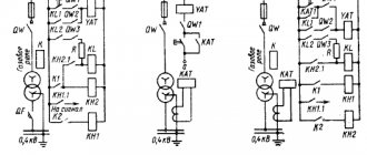
Actions when the transformer differential protection is triggered are illustrated in Fig. 1.
Current transformers TT1 and TT2 are installed on both sides of the transformer, the secondary windings of which are connected in series. A current relay T is connected in parallel to them. If the characteristics of the current transformers are the same, then in normal mode, as well as during an external short circuit, the currents in the secondary windings of the current transformers will be equal, their difference will be zero, and no current will flow through the winding of the current relay T, therefore, the protection will not apply.
In the event of a short circuit in the transformer and at any point in the protected zone, for example in the winding of the transformer, current will flow through the winding of relay T, and if its value is equal to or greater than the relay operating current, then the relay will operate and, through the appropriate auxiliary devices, will perform a two-way shutdown of the damaged plot. This system will operate during phase-to-phase and interturn faults.
Differential protection is highly sensitive and fast-acting, since it does not require a time delay, it can be performed with instantaneous action, which is its main positive property. However, it does not provide protection against external short circuits and can cause nuisance tripping if there is an open in the secondary circuit connecting wires.
Rice. 2. Differential protection of two parallel operating transformers
The coverage area of the differential protection of a transformer (DTP) is limited to the installation site of the current transformers, and includes the MV, LV busbar and the connection of the TSN connected to the LV bus bridge.
Due to its comparative complexity, differential protection is installed in the following cases:
- on single operating transformers (autotransformers) with a power of 6300 kVA and above;
- on parallel operating transformers (autotransformers) with a power of 4000 kVA and above;
- on transformers with a power of 1000 kVA and above, if the current cut-off does not provide the necessary sensitivity during a short circuit on the higher voltage terminals (kch < 2), and the maximum current protection has a time delay of more than 0.5 seconds.
Application of differential protection
Differential protection has found its practical application as the most important protection of transformers and autotransformers. However, due to a number of disadvantages:
- complexity and high cost of production;
- the need to create an interference-proof line to protect signals coming from current transformers to the current relay;
- the need to take a number of measures to reduce the unbalance current
This type of relay protection is used only:
- for transformers or autotransformers with a power of 6300 kVA and above, operating alone;
- for transformers and autotransformers with a power of 4000 kVA and above, operating in parallel;
- for transformers with a power of 1000 kVA and above in the event that the current cut-off does not provide the required sensitivity during a short circuit on the high voltage terminals, and the response time of the maximum current protection is more than 0.5 sec.
Kinds
Despite the fact that differential protection is a fairly popular method of protecting transformers, it cannot be used everywhere. This is due to the fact that the scope of activity extends to devices with limited power ratings.
Current cut-off
If a device, including an automobile transformer, operates at a power above 6,300 kV-A (single) or from 4,000 kV-A (multiple parallel), then the only convenient and rational method of protection is current cutoff.
The action is based entirely on the operating principles of current line cutoff. During a short circuit, the current at the inputs is significantly greater than on the load side. The cut-off current is selected depending on its operation during a short circuit - it should not operate.
The formula takes into account the indicators of the maximum current, which, passing through the inputs, is transmitted further, and the cutoff reliability coefficient (selected from the tabular data). Sensitivity is taken into account - it is characterized by a certain coefficient. This indicator is no less than two.
Gas
Another common method of protection is gas. It is used on various types of equipment, but only if there is oil cooling with expanders. They are required from a technological point of view for the operation of such devices:
- transformers and autotransformers with a power of 6,300 kVA and more;
- equipment with a power from 1000 to 4000 kVA, which are not equipped with cut-offs and differential protection;
- devices with the above indications, which have a maximum current protection characteristic of 1 second or more.
If a transformer with average power ratings already has another protection installed, for example, differential or cutoff, then using gas protection is not necessary. But if the device operates inside a workshop, its power exceeds 630, then gas protection is required, even if other types.
From overcurrents
A technique for protecting vehicles from overcurrents is also used. It turns off the power supply if there is damage to the internal part of the mechanism, including switches and tires.
Overload is usually symmetrical; to protect against it, maximum current protection in one phase is used. If the equipment is located in a serviced room, then the delay time is for the signal; in unserviced rooms - for unloading or shutting down. The type of installation depends on the number of windings. For two windings they are located on the main power side, and for three windings they are on the side of the winding where there is no power and on the power side. When operating options with three-way power supply, three devices are used on all sides.
Additional current transformers are required for protection against frame faults. It is inserted into the grounding bus between the circuit and the housing. At the same time, the current snout on the secondary is turned on.
It is worth paying attention to the fact that the protection mechanism is selected depending on the design features. The characteristics of power and current are also decisive.
BMRZ blocks
Differential is used as the main high-speed one. They are necessary to protect the terminals, the internal structural part. Connection to the BMRZ unit occurs according to the star circuit. This does not take into account groups and connection patterns.
The main thing is that the device ensures the supply of secondary currents in a positive direction (towards the device for which they are intended to protect against short circuits). A two-phase connection is made only if it is necessary to supply a common current pulse of phases A and C in antiphase in the triangle. Please note that:
- primary currents are out of phase, their values are not equal in the module;
- the shear angle depending on the variation in the connection of the primary and secondary;
- differences in coefficients lead to increased unevenness of secondary currents;
- limited use of intermediate devices is achieved due to leveling;
- phase rotation compensation is achieved by skewing the triangle.
If the short circuit is external, then the current flows only through the star-connected phases. If the winding is of the triangle type, then the currents move around the perimeter of the figure, while they are not present in the phases. Zero sequence currents are not taken into account in calculations.
There are two types of protection in DMRZ units: DTO and DZT. The first is stopped at the indicator of unbalance amplification in short-circuit mode, but in any case it is not always equal in terms of sensitivity coefficient. To achieve this goal, a DZT is used, which operates when a braking current is observed.
The calculation is carried out programmatically, taking into account the transformer’s own currents. The magnetizing current is only in the voltage-receiving winding. The block is installed separately for any circuit. In some cases, cross-blocking is more effective.
Selection of primary CTs and PTNs of BMRZ units
The CTs used must comply with the protection relay requirements. Issues of temperature stability are discussed separately. The following indicators are calculated:
- maximum phase current flowing through the device;
- minimum phase current;
- rated current coefficients;
- operating current is average.
The average knowledge of the maximum error of 0.1 is taken into account, if the current multiplicity is not more than the rated one, the same conditions apply to the load. Minimum error 0.5.
The setting is determined by the program if at max. It is not possible to select the PTN current value, then choose the option with a multiple of the primary current of 10 percent of the error and no more than 20 percent.
Differential current cut-off
DTO influences the configuration of equipment and the protection of various structural units. In particular, detuning is provided from:
- BTN;
- unbalance current.
The maximum value is taken from two possible values for triggering the cutoff. The standard indicator is selected at the level of four or five nominal coefficients.
When calculating the unbalance current, many characteristics are taken into account, including the detuning coefficient, the CT error coefficient during transition, the periodicity of the external pressure phase current, the maximum and minimum error values, relative errors and distribution currents.
Current differential protection with braking
Differential protection is calculated in a similar way. Relative errors are defined as half of the control range. Extreme coefficients are understood only if this does not affect the sensitivity characteristics.
Braking conditions will vary depending on the vehicle being used. If we are talking about two-winding, then the error coefficients are not taken into account; they are taken equal to unity. Be sure to consider the connection diagram of the windings and elements; only in this case is it possible to correctly calculate the circuits.
Part 2. Differential motor protection
According to the requirements of the PUE [2], electric motors with a power of 5 MW or more, having leads from the beginnings and ends of phase windings, must be protected [1] from phase-to-phase faults using differential current protection.
Electric motors with a power of less than 5 MW must be equipped with the same protection if the TO sensitivity coefficient (see [1]) is less than or equal to 2.
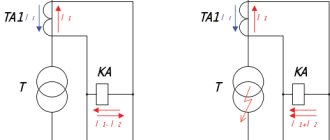
Measuring element D (Fig. 1) determines the value of the differential current Id equal to the geometric sum of the currents of the current transformers TA1 and TA2.
During a short circuit inside the protected zone K1 (internal short circuit), the measured currents I 1 and I2 are practically in phase, therefore the differential current Id is significantly greater than zero and is comparable to the geometric sum of these currents (Fig. 2, a).
For a short circuit outside the K2 zone (external short circuit), the geometric sum of currents (differential current Id) in the ideal case (in the absence of errors in current transformers) is zero (Fig. 2, b).
Rice. 2 Vector diagrams of currents for internal (a) and external (b) short circuit [3]
To ensure correct operation of the protection both during external and internal short-circuits, digital devices use an algorithm (Fig. 3) that provides braking (coarsening of the operation setting Id mouth) with an increase in the compared currents.
The use of such an algorithm ensures non-selective operation [2] of protection during external short-circuits and selective operation during internal short-circuits, and in the case of correctly selected settings, non-operation during external short-circuits.
This algorithm generates two signals:
- differential current Id = ∑I, the absolute value of which is Id = |∑I|;
- braking current Ibr, equal to the sum of the absolute values of the compared currents Ibr = ∑|I|.
Comparison of braking and differential currents occurs in the BS comparison block. The braking algorithm used in the BMRZ units will be discussed in detail in the next article.
The characteristics of differential current protection are shown in Fig. 4.
Rice. 4 Characteristics of DTO and DZT
Differential protection of electric motors can be implemented in two- or three-phase versions.
Two-phase differential protection can be performed when combined with one of the protections against:
- ground faults;
- double ground faults using a zero-sequence current transformer and a current relay.
In all other cases, differential protection must be performed with three current transformers.
In accordance with the requirements of the PUE for electric motor-transformer (autotransformer) units with a power of more than 2 MW, a differential cut-off in a two-relay design must be provided, detuned from surges in the magnetizing current of the transformer.
Electric motor-transformer (autotransformer) units with a power of less than 2 MW must be equipped with the same protection if the TO sensitivity coefficient (see [1]) is less than or equal to 2 with a phase-to-phase short circuit at the motor terminals.
For electric motor-transformer (autotransformer) units, differential current protection in a two-relay design with intermediate saturable current transformers must be provided.
Electric motor-transformer (autotransformer) units with a power of less than 2 MW must be equipped with similar protection if the technical equipment (see [1]) does not meet the sensitivity requirements.
According to [1], the sensitivity of differential protection should be assessed using the sensitivity coefficient, defined as the ratio of the calculated value of the differential current for a metallic short-circuit within the protected area to the value of the differential current at which the protection operates.
Note that when using digital relay protection devices, the implementation of two- and three-phase versions of differential protection does not present any difficulties, since these devices provide the required number of digital overcurrent relays for each phase.
There are two known options for differential current protection of electric motors:
- with an operating current less than the rated current of the protected electric motor;
- with an operating current greater than the rated current of the protected electric motor.
The first protection option is used at facilities with permanent maintenance personnel.
When using it, you should take into account the possibility of incorrect operation of the motor protection when:
- breakage or other malfunction of current circuits;
- malfunction of one of the current transformers.
However, this protection option ensures that the amount of damage to electric motors is minimized during internal phase-to-phase short circuits in the stator winding of the machine.
The second protection option is recommended for use at critical facilities and ensures its correct operation when:
- breakage and malfunction of current circuits;
- malfunction of one of the current transformers.
Differential current protection with braking (DZT) is the main one. Together with it, differential current cut-off (DCT) is used, which is auxiliary in relation to DCT.
There are versions of the BMRZ-100 series units in which only the DTO algorithm is provided (Fig. 5), and the DZT algorithm is absent.
Rice. 5 Algorithm for differential current cut-off in the BMRZ block
In block A1 of such an algorithm, the maximum values of currents from the supply side of the protected object Iв are identified, and in block A2 - the maximum values of currents from the common point (neutral) of the protected object Iн.
The differential current is calculated by block A3 using formula (9) [3]:
id(t) =iв<(t) —iн(t) (9)
A4 generates an output signal when condition (10) is met:
|id(t)| ≥IDTO (10)
where IDTO is the ATD response setting.
In this version of the algorithm, element A5 is provided [4], which ensures its operation with a delay in response time. When the minimum setting is set, the DTO is triggered in no more than 35 ms at a differential current multiple of 1.2 relative to the setting.
The S910 software key disables the DTO algorithm, and the S 910 key ensures that the algorithm is disabled.
Block A6 prohibits the algorithm from turning off when a “Fault” signal is received at the input of the device.
Considering that the use of only the DTO algorithm in a block without the DZT algorithm is not recommended by some experts, all blocks of the BMRZ and BMRZ-100 series produced since 2009 provide for the use of both algorithms.
General principles for selecting DZT settings
When it is necessary to reduce the unbalance component, BMRZ blocks with separate characteristics are used. These include taking into account the position of the device. There are types:
- rude;
- sensitive.
The first type of installation includes all average regulatory provisions (up to half the deviation). For sensitive ones, variations with deviations of no more than 5 percent from the original indicator are chosen. Sensitivity increases if you reduce the current when calculating the position of the transformer.
The selection principle is to find the correct switching group. The conditions for using the blocks are given in the instructions for the devices. Modern options switch automatically, while the unit itself is responsible for sending the signal. It is important to carry out such actions as setting the primary current, setting the unbalance signal.
Selecting the setting for the initial operating current of the DZT
At this stage, the detuning conditions become an important characteristic. They are calculated from the maximum unbalance current when the load is on. Accounting occurs in two switch modes. The data is checked once for the coarse type, and the second for the sensitive type. Afterwards, the indicators are summed up and the statistical average is calculated.
The current readings vary depending on the number of winding layers. For two-winding or three-winding options, the current indicators will be different.
Selecting the braking coefficient setting for the second section, characteristics
This coefficient is calculated using the formulas for detuning conditions depending on the nominal unbalance current, which appears with the braking current at the end of the last section.
The type of sensitivity of the installation is taken into account - calculations are carried out twice. Rough is taken if voltage regulation in the sources does not occur and has no effect. Typically, for calculations, a value equal to the minimum input is accepted.
Selecting the third section braking coefficient setting, characteristics
Here, the conditions for detuning the operation from the unbalance current under conditions of maximum short-circuit indicators are taken into account. For the calculation, data is required on the error magnification factor (it is taken as standard equal to 2.5), phase current, maximum error, and rated secondary current pulse.
Checking the sensitivity of the DZT
Sensitivity is calculated at the terminals when operation is carried out in the usual mode on the branch. According to standards, the coefficient should not exceed two. But in some cases the reduction is impossible for technical reasons. The value is taken to be 1.5 or so if:
- power characteristics at the terminals of the lowest device are less than 800 mVA;
- if there is no power supply to one of the sides;
- when energized on one side;
- in short circuit mode behind the reactor.
If other protective mechanisms are present, then it is permissible not to use it. All attention is paid to the sensitivity coefficient and the possibility of excluding the device is judged by its features. The coefficient is calculated if the mineral value of the imbalance is more than a tenth of a unit.
Unbalance Alarm Setpoint Selection
The criteria are selected in such a way that the coefficient is within reasonable limits. The detuning coefficient indicators are taken into account (additional 10-20 percent are invested), as well as the maximum temporary reserve indicators.
Selection of DZT settings in the presence of TSN in the protection zone
The coefficient in this case will be equal to 1.5. The frequency of current flow through the phases and the indicators of the normal current that is supplied to the primary winding of the transformer are taken into account. Additionally, data on the operating current that occurs in load mode is considered.
Selecting the settings for blocking the DZT when a BTN occurs
It is necessary to take into account all the above instructions, but in addition, the instructions are supplemented by other points. Among them:
- cross-blocking should be used only in cases where it is required by the characteristics of the winding connection group;
- if it is possible to trace the reasons for the vehicle shutdown and eliminate them, then cross blocking is not used;
- if the identified cause is an unacceptable IPB value for carrying out the block, then turn on the equipment again.
The time setting is about one second for equipment of medium and low power, for large values the standard is 2 seconds.
Calculation of differential current protection of a two-winding transformer with splitting.
Since the power of the power transformers is 25 MVA, we choose protection using relays of the DZT - 11 type.
Equivalent circuit of a transformer with splitting.
Ohm
Ohm
Ohm
Ohm
We determine the primary currents for all sides of the protected transformer, corresponding to its rated power. Based on these currents, the corresponding secondary currents in the protection arms are determined based on the transformation ratios of the current transformers nt and the circuit coefficients kсх. The calculations are summarized in Table 1.
Table 1.
| Name quantities | Designation and determination method | Numeric value | |
| 110 kV | 10 kV | ||
| 1.Primary current on the sides of the protected transformer | |||
| 2. Current transformer connection diagram | —— | ||
| 3. Transformation ratio of current transformers | nt | 200/5 | 1500/5 |
| 4. Secondary current in the protection arms | |||
For the main zone, the minimum protection operation current is determined by the condition of detuning from the magnetizing current surge when turning on the loaded transformer under voltage:
We determine the number of turns of the working winding of the BNT relay for the main side of 110 kV and for the 10 kV side, based on the value of the minimum protection operation current.
The calculations are summarized in Table 2.
Table 2.
| Name of quantity | Designation and method of determination | Numeric value |
| 1. Relay actuation current on the main side, A | ||
| 2. Number of turns of the BNT winding relay for main side: — calculated - previously accepted | Wosn | 12 |
| 4. Number of turns of the NTT relay winding for the non-main side: — calculated - previously accepted | W1 | 14 |
I accept the following numbers of turns for use: Wmain = 14 turns, which corresponds to
A
Determination of currents.
In case of separate operation of transformers:
Ohm
A
This is the amount of current flowing through the protection during an external short circuit.
In case of parallel operation:
Ohm
A
Current flowing through one transformer:
A
To determine Inb.ras. the calculated value is the largest value of A
The calculations are summarized in Table 3.
Table 3.
| Name of quantity | Designation and method of determination | Numeric value |
| 1. Primary rated unbalance current taking into account the short-circuit component. on NN, A tires. | ||
| 2. Number of turns of the brake winding of the BNT relay: — calculated - accepted | Wtor | 7 |
We determine the sensitivity of protection during short circuit. between two phases in the minimum operating mode of the system.
A
Requirements for formatting calculation results
There are certain requirements for the design of settlement procedures. This allows calculations to be made in a way that is understandable for other radio amateurs and specialists who will use the information later if the situation requires it.
A special assignment form is issued. If we are talking about large-scale production, then authorized employees deal with this issue. If you do the calculations yourself, it is recommended to download the samples on the Internet. The form includes information about settings and keys. Specialists undertake to be guided by the schematic solutions that are presented in specific instructions.
Calculation examples
Double winding transformer
The solution to the problem begins with determining the indicator from the inrush of the magnetizing current and from the unbalance current. The first is equal to the product of the detuning coefficient and the data on the rated current of the vehicle. The value of the second is also the product of the safety factor and the unbalance current.
The negative position of the current is calculated, and the unbalance current includes the data of all. The coefficients of the aperiodic component and uniformity, three-phase short circuit are taken into account. Next it is calculated:
- relay operating current;
- number of turns of the HV winding;
- number of LV turns;
- protection sensitivity factor.
Two-winding transformer with split LV winding
A device with splitting of the low voltage winding is considered as two two-winding. In this case, a prerequisite is that they are powered from a common network.
The data is entered into the general scheme, the calculation is carried out according to an identical algorithm to the previous one. The only exception is the last stages, when the designation of the number of turns and the influence of the load on this is carried out.
Three-winding power transformer
Calculating the differential protection of a vehicle with three windings will take a little longer, since the coefficients for each circuit are isolated. The algorithm of actions is as follows:
- determination of primary rated currents for HV, MV and LV;
- determination of secondary rated currents, taking into account the type of connection;
- selection of working branches;
- calculating the estimated device unbalance coefficient using tabular data;
- determination of differential operating current;
- sensitivity of the braking indicator.
At the last stage, it is determined whether the conditions for comparing the operating current depending on the applied load are met. There must be more than two.
On step-down transformers
Step-down transformers also need a differential. protection as the other type. The calculation is carried out in a similar way, that is, first the currents and unbalance are calculated, and the coefficients are checked.
It is important to pay attention to the connected loads and their power ratings. When calculating step-down equipment, this is a prerequisite.
Calculation of transformer differential protection settings
Differential protection of the transformer is performed using the 7UT6 device. To select its parameters, you first need to select the transformation ratios of the current transformers installed on all sides of the protected transformer. Methodology for this selection
is given in table 0.2
Table 0.2 – Selection of current transformers on the sides of the protected
When choosing the protection operation current, it is necessary to ensure that the protection does not operate in two operating modes of the protected transformer:
- when the transformer is turned on only from the power source side, when at the moment of switching on, significant surges of magnetizing current appear in the supply winding of the transformer.
To tune out the magnetizing current surge when the transformer is turned on, the device is equipped with current filters for the second and fifth harmonics. The manufacturer's recommended response setting is 20% of the first harmonic component of the differential current.
- for three-phase short circuits outside the protection coverage area (fault on low voltage busbars), when the maximum through current of an external short circuit passes through the transformer. This is ensured by the use of the braking characteristic of the 7UT6 relay.
The braking characteristic has a constant braking coefficient.
It was selected based on the condition of detuning from unbalance currents under external short circuit and limiting conditions:
- error of current transformers: 10%;
-range of regulation of on-load tap-changer by transformer: 12%;
- error due to inaccurate alignment of currents in the protection arms: 5%.
Total: K T
1,5 (0, 10 0,12 0,05) 0,40.
The braking characteristic of the sensitive stage of the differential protection of the 7UT6 device has a constant braking coefficient equal to
0,5.
The braking start current is selected based on the consideration that braking does not operate at the rated load current of the transformer. Since the current transformers of the LV side are selected according to the rated current of the power transformer, therefore, at load currents less than the rated ones, a secondary current of less than 5 A will flow in the relay. To ensure that no braking action from load currents is applied, the starting current of braking can be taken equal to
Ibr. = 5.0 A.
The settings are calculated:
— current equalization coefficients are determined for each side.
For the HV side, where the current transformers are assembled into a triangle, the equalization coefficient is determined by the formula:
I NOM TT VN
. . (4.3)
K.B.
1
| . |
| . |
| 3 |
| NOMTRVN |
| I |
| |
where I NOM CT HV
. . — rated primary current of the current transformer installed on the HV side of the transformer;
I NOM TR VN
. . — rated current of the HV side of the power transformer.
K.B.
1
| 200 |
| 3158 |
| |
0.73, we take K V
1 0.73.
For the MV side, where the current transformers are assembled in a star, the equalization coefficient is determined:
K.B.
2 tH L3p58HjDe7/JFpNt1UC9bxwbiGcRKOLClQ1XBj63rzdzUD4gl9g6JgNn8rDILy8yTEs38gcNm1Ap KWGfooE6hC7V2hc1WfQz1xFLdnC9xSC2r3TZ4yjlttVJFD1oiw3LQo 0drWoqjpuTNfA24ri8jV+G 9fGwOu+29+9f65iMub6als+gAk3h7xh+8AUdcmHauxOXXrUG5JHwq5I93YnbG3hMEtB5pv+z598A AAD//wMAUEsBAi0AFAAGAAgAAAAhALaDOJL+AAAA4QEAABMAAAAAAAAAAAAAAAA AAAFtDb250 ZW50X1R5cGVzXS54bWxQSwECLQAUAAYACAAAACEAOP0h/9YAAACUAQAACwAAAAAAAAAAAAAAAv AQAAX3JlbHMvLnJlbHNQSwECLQAUAAYACAAAACEAJHBMOOMIAAAxNwAADgAAAAAAAAAAAAAAAu AgAAZHJzL2Uyb0RvYy54 bWxQSwECLQAUAAYACAAAACEAO2gx2tsAAAADAQAADwAAAAAAAAAAAAAA AAA9CwAAZHJzL2Rvd25yZXYueG1sUEsFBgAAAAAEAAQA8wAAAEUMAAAAAA== ">
| 400 |
| 3300 |
| |
0.76, take K V
1 0.76.
K.B.
2
| 600 |
| 3945 |
| |
0.36 we take K V
2 0.36.
— the operating current of differential protection and differential protection is selected.
The setting of the sensitive stage of differential protection is selected in fractions of the rated current of the transformer: I DT
0.51.0 (in fractions of the rated current of the transformer).
SR
For a transformer with a power of 63 MV A, we accept the setting of the sensitive stage of differential protection in fractions of the rated current of the transformer
I DT
1,0
SR
After selecting the equalization coefficients, the current settings are determined by the formulas:
5 I DT
I UST
SR
, (4.5)
K.B.
1
where 5 is the rated secondary current of the current transformer;
I DT
— differential protection setting in fractions of the rated current of the transformer
SR
(take equal to 0.5÷1.0);
K.B.
1 - current equalization coefficient for HV.
5 I DT I UST
SR
,(4.6)
K.B.
2
I UST VNDT
.
6 . A
To ensure a valid protection response setting that is not less than the previously selected setting, it is necessary to accept the nearest higher setting that can be set in the 7UT6 device. Therefore, the setting of the protection operation current on the HV side is accepted I UST VNDT
.
6 . A
I UST SNDT
.
6 . A
Based on the considerations mentioned earlier, the protection current setting on the MV side is taken I UST SNDT
.
6 . A
I UST NNDT
.
13 . A
Based on the considerations stated earlier, the protection current setting on the LV side is taken I LVDT setting
.
7 . A
The actual operating current of the sensitive stage of the differential protection will be equal to:
I DT
I NW VNDT
.
SET HV
.
K CT HV
. , (0.2)
K CX VN
.
where I UST VNDT
.
— installation current of the protection operation on the HV side; K TT HV
.
— current transformer ratio on the HV side; K CX VN
. — circuit coefficient on the HV side.
I NW VNDT
. 6,8 100 / 5 158 .
A
| 3 |
Let's check the sensitivity coefficient of protection during a short circuit on the LV side (at point K2) in the absence of braking using the formula:
k H
I short circuit
(2).max , (0.3)
I SRTO
.
where I short circuit
(2).min - minimum two-phase short circuit current at point K2;
I SRTO
. — operating current of the current cut-off relay.
Using the known value of the three-phase short-circuit current in the minimum mode at points K2 and K3, we find the two-phase short-circuit current using the formula:
I short circuit
(2)
| 3 |
| 2 |
I short circuit
(3) , (0.4)
I short circuit
(2) 3 852 73 .
A
2
158
kH
2,1 2
| 3 |
73
I short circuit
(3) 294 25 .
A
2
158
kH
6,2 2
73
It follows that the sensitive differential protection stage of the 7UT6 device satisfies the sensitivity coefficient requirements.
The coarse stage of the differential cutoff is adjusted from the inrush of the magnetizing current according to the value of the operating current setting. For average
conditions, its operation current should be equal to (5÷6)·Inom. t-ra.
The coarse stage of the differential cut-off is not adjusted in time to the inrush of the transformer magnetizing current and must be adjusted according to the current. You can take the current setting equal to 5·Inom.t-ra at a voltage of 35 kV
or 6·Inom.t-ra - at a voltage of 110 kV.
Therefore, the setting of the coarse diffusion cut-off stage in fractions of the rated current of the transformer is selected equal to: IDT
6,0.
SR
The secondary operation current is determined by the previously given formula: 5 I TO
I UST VNDO
.
SR
; (4.10)
K V
1
I UST VNDO
.
41 . A
On the HV side, we accept the nearest higher setting, which can be set in the 7UT6- I UST VNDO
.
41 . A
5 I TO
I UST SNDO
.
SR
;
(4.11) K V
3
I UST SNDO
.
39 . A
On the MV side, we accept the nearest large setting, which can be set in the 7UT6- I SET NNDO
.
40 . A
I UST NNDO
.
81 . A
On the LV side we accept the nearest large setting, which can be set in the 7UT6- I UST NNDO
.
81. And
the actual operating current of the coarse stage of the differential cut-off will be equal to:
I NW VNDO
.
| 41200/5 |
| 3 |
| |
947 . A
Let's check the sensitivity coefficient of the differential cutoff during a short circuit on the MV side (at point K1) using formula (4.9).
Using the known value of the three-phase short-circuit current in the minimum mode at point K1, we find the two-phase short-circuit current using the formula:
I K
(2)1min 3 1354 1171 .
A
2
kH
1.
It follows that the coarse diphoto-cutting stage of the 7UT6 device satisfies the requirements for the sensitivity coefficient.
Selecting the response time of differential protection and differential cutoff.
As a first approximation, we can assume that with an operating current equal to 0.5 of the rated current of the transformer, the time delay must be set to about 0.20 s, and with an operating current equal to the rated current - about 0.10 s.
Therefore, we will take the delay setting for the response time of the differential protection and differential cutoff to be equal to 0.10 s.