Ideal voltage source
Ideal current and voltage sources are idealized energy sources. They have the ability to transfer energy to the parts of the electrical circuit connected to them; in other words, the energy they consume can be negative. Thus, ideal current and voltage sources refer to idealized active elements.
An ideal voltage source (voltage source, emf source) is an idealized active element, the voltage at the terminals of which does not depend on the current flowing through it. The voltage and at the terminals of the voltage source is equal to the electromotive force e (t) and can be an arbitrary function of time. In a particular case, e (t) = E_ may not depend on time. A source of this type is called a constant voltage source (constant emf source). The conventional graphic designation of the voltage source is shown in Fig. 1.12, a. The arrow inside the circle in the figure indicates the direction of e. d.s. For constant voltage sources, it is directed from the lower potential terminal to the higher potential terminal, while the voltage at the external terminals of the source is directed from the higher potential terminal to the lower potential terminal.
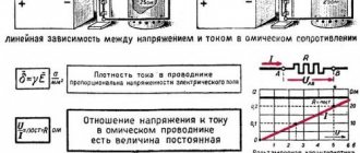
An external characteristic of any source of electrical energy is the dependence of the voltage at its terminals 01 of the source current. The external characteristic of a constant voltage source is a straight line parallel to the current axis (Fig. 1.12, b).
If you connect to the terminals of the source e. d.s. load resistance
As the load current decreases, the power released in it increases without limit. Because of this, the voltage source is sometimes called an infinite power source.
Operating modes of the E.M.F. source
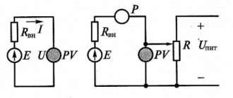
⇐ PreviousPage 3 of 4Next ⇒Fig.3.5. Scheme of a real EMF source with a load.
Idle mode (key S is open) (Figure 3.5). The open-circuit voltage at the output of the source is equal to its EMF (UХХ = E), the no-load current is zero (IХХ = 0), because the load resistance is equal to infinity (RN = ¥), the efficiency factor (C.P.D.) with an ideal EMF source in this mode tends to unity (h = 1).
1. Nominal mode is the mode for which the source is designed (switch S is closed). In this mode, source E operates efficiently in terms of reliability and efficiency
IN = INOM = , UOUT = UNOM,
h =
< 1.
2. Coordinated mode - a mode in which maximum power is supplied to the load.
Source power: P
И=
E×I
Load power: P
Н=
U
LOAD×
I
LOAD
I
LOAD = ,
U
LOAD =
I
LOAD
R
Н =
R
Н,
hence
P
N =
U
LOAD×
I
LOAD =
R
N
I
2LOAD = ( )2
R
N.
Question: “At what value of RN will the power in the load have its maximum value?”, i.e. it is necessary to determine the extremum of the function PH(RNH). To do this, take the derivative of the expression P
n=
R
n ·
I
2=
E
2 ·
R
/(
R
+
R
)2.
The maximum power value will be at =0. This will happen at Rн=Rвн.
Efficiency: h=Pn/Pi=E2×R/(Rin+Rn)2×(Rin+Rn)/E2=Rn/(Rn+Rin) =1/(1+Rin/Rn)
Thus, in a coordinated manner
Pvolt=Pmax=Pist/2; Un=E/2; Iн=Iк.з/2; Rн=Rвн; h
=0.5
4. Short circuit mode – mode when the load resistance is zero.
In this mode: Rн=0, Un=0, Iкз =E/Rвн, h=0, Pist= Рвн= Iкз× E, Рн=0.
Rice. 3.6. Dependence of powers: source, receiver and losses on current.
As can be seen from Fig. 3.6, the power loss is a parabola in accordance with the formula Pin = RinI2
, and the source power is a straight line in accordance with the formula
Pi = EI
, then the load power, in accordance with the power balance
Pi = Pin + Pn
, will have the form of an inverted parabola, because
Pn= Pi-Pin
.
Power balance , definition - “The sum of the powers of the sources is equal to the sum of the powers of the receivers and the powers of losses .
Rice. 3.7. External characteristic of a real source of E.M.F.
The external characteristic of a real EMF source is a falling straight line in accordance with the formula of Kirchhoff's second law Un=E-Uin=E-RinI
.
The voltage drop across the internal resistance is a growing straight line Uin=RinI
.
| Rн |
| Uvn |
| Un |
| Un |
| Uvn |
| In |
| In |
| E |
| E |
| E |
| Rin |
| E |
Rice. 3.8. Dependence of voltage drops at the source, receiver and current on the value of the load resistance.
In Fig. Figure 3.8 shows the dependences of the voltage drops at the source, receiver and current on the value of the load resistance. As you can see, these dependencies have the form of a hyperbola. Indeed, in the formula E and R
vn are
constant quantities, and R
n
is a variable quantity, which means this is a hyperbola equation. The graph of the voltage drop across the internal resistance is also a hyperbola, because according to Ohm's law Uin = RinIn , Rin is
a constant value, and the graph In (Rn) is
hyperbola, which means
Uin(Rin) is also a hyperbola.
Questions about the topic of the lecture.
1. Condition for circuit equivalence.
2. Equivalent resistance with series resistance, diagram, formula.
3. Equivalent resistance with parallel resistance, diagram, formula.
4. Converting a real EMF source into an equivalent current source. Scheme, formula.
5. Converting a real current source into an equivalent EMF source. Scheme, formula.
6. Converting a resistance triangle into an equivalent star, diagrams, formulas.
7. Conversion of resistances assembled according to a star circuit into an equivalent triangle, circuits, formulas.
8. Theorem about the equivalent generator (Helmholtz - Te Ve Nen), seme formula.
9. Theorem about equivalent current source (Norton).
10. Operating modes of the EMF source (types).
11. Idling of the EMF source, diagram, conditions of conduction, why it is carried out.
12. Nominal operating mode of the EMF source, definition, formulas for voltage drop: across the load, across the internal resistance.
13. Nominal operating mode of the EMF source, definition, current formulas and efficiency.
14. Nominal operating mode of the EMF source, definition, power formulas: source, receiver, losses.
15. Power balance, definition, formula.
16. Coordinated operating mode of EMF sources, where applicable.
17. Condition for the occurrence of an agreed operating mode, proof.
18. Short circuit mode EMF, short circuit current, formula.
19. Dependence of power and efficiency on current, formulas confirming the appearance of these graphs.
20. Dependences of EMF, voltage drop across the load and internal resistance on current, formulas confirming the appearance of these graphs.
21. Dependences of EMF, current, voltage drop on the internal resistance and on the load on the value of the load resistance.
Lecture 4.
⇐ Previous3Next ⇒
Conflicts in family life. How can I change this? It is rare that a marriage and relationship exists without conflict and tension. Everyone goes through this...
What to do if there is no reciprocity? And now let's come down from heaven to earth. Have you landed? Let's continue the conversation...
Live by the rule: IS THERE NOT MUCH THING IN THE WORLD EXISTING? It is no coincidence that I emphasize that the space in your head is limited, but there is a lot of information around, and that your right...
What will happen to the Earth if its axis shifts by 6666 km? What will happen to the Earth? - I asked myself...
Didn't find what you were looking for? Use Google search on the site:
Ideal current source
An ideal current source (current source) is an idealized active element whose current does not depend on the voltage at its terminals. The source current i=j(t) can be an arbitrary function of time; in a particular case, it may not depend on time i(t) = J_ (direct current source). The external characteristics of the DC source are shown in Fig. 1.14, b.
The conventional graphic designation of the current source is shown in Fig. 1.14, a. The double arrow in the figure shows the direction of the current inside the source. For direct current sources, this direction coincides with the direction of movement of positive charges inside the source, i.e., with the direction from a terminal with a lower potential to a terminal with a higher potential.
The current of the current source and the voltage of the voltage source are parameters of idealized active elements, just as resistance, capacitance and inductance are parameters of the same idealized passive elements.
If you connect the load resistance to the external terminals of the current source (Fig. 1.15), then according to (1.9), (1.11) the voltage at the load resistance and the power released in the load will be equal, respectively:
As the voltage across the load increases and the power released in it increases indefinitely, therefore the current source, like the voltage source, is a source of infinite power).
The dependence of the current of the current source on the voltage has the same form as the dependence of the voltage of the voltage source on the current, therefore these sources are dual elements.
Reactive internal resistance
Impedance
In addition to galvanic and electrolytic two-terminal networks, there are power supplies whose circuits include reactive elements. When determining their internal resistance, the complex amplitude method is used. It involves using the complex resistances of the elements included in the circuit in calculations. The values of currents and voltages are replaced by the values of their complex amplitudes. The calculation algorithm itself is the same as when calculating active resistance.
The process of measuring r-reactance is slightly different from measuring the active component of resistance. The methods depend on what parameters of this complex function need to be learned: individual components or a complex number.
These parameters are affected by frequency, therefore, in order to obtain information about the internal reactive value r during testing, it is necessary to remove the frequency dependence. This is achieved by a set of measurements over the entire frequency range generated by such a two-terminal network.
Equivalent circuits for real sources
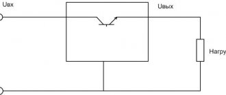
Idealized current and voltage sources can be considered as simplified models of real energy sources. Under certain conditions, in a fairly narrow range of currents and voltages, the external characteristics of a number of real energy sources can approach the characteristics of idealized active elements. Thus, the external characteristic of a galvanic element in the region of low currents has a form close to the external characteristic of the voltage source (see Fig. 1.12.6), and the external characteristic of the output stage on a transistor in a certain voltage range approaches the external characteristic of the current source (see Fig. 1.14.6).
At the same time, the properties of real energy sources differ significantly from the properties of idealized active elements. Real energy sources have finite power; their external characteristic, as a rule, is not parallel to the current axis or voltage axis, but intersects these axes at two characteristic points corresponding to the idle and short circuit modes (sometimes special types of protection are used in energy sources that exclude operation in extreme modes or in one of them).
With sufficient accuracy for practice, the external characteristics of most real energy sources can be approximately represented by a straight line intersecting the current and voltage axes at points 1 and 2 (Fig. 1.16, a):
corresponding to idle and source short circuit modes. Sources that have a linear external characteristic will be further called linearized energy sources (real).
Let us show that a linearized energy source can be represented by a modeling circuit consisting of an idealized voltage source E and internal resistance or an idealized current source J and internal conductivity. Indeed, the equation of a straight line passing through two points with coordinates has the form
Substituting (1.28), (1.29) into (1.30) and representing voltage u as a function of current i, we find an analytical expression for the external characteristic of the linearized source
In accordance with (1.31), the voltage of a linearized source consists of two components. The first one has the dimension of voltage and does not depend on the current flowing through the source. It can be interpreted as the voltage of some ideal voltage source with e. d.s. The second component of the source voltage is directly proportional to the current. It can be considered as a voltage drop across a certain resistance through which the source current i flows (this resistance will be called the internal resistance of the source in the future). So, equation (1.31) can be associated with the equivalent circuit of a linearized source, shown in Fig. 1.16, b. This replacement scheme is called
consistent. You can verify that the dependence of the voltage at the terminals of this circuit on the current is determined by the equation
equivalent to equation (1.31) and, therefore, the external characteristic of the circuit has the form shown in Fig. 1.16, a.
From the analysis of expression (1.32) it is clear that with a decrease in the internal resistance of the source, the external characteristic of a linearized source approaches the external characteristic of an ideal voltage source (Fig. 1.17, a). At = 0, a source with a linear external characteristic degenerates into an ideal voltage source. Thus, an ideal voltage source can be considered as an energy source whose internal resistance is zero.
Consider another linearized source equivalent circuit that contains an ideal current source. To do this, using (1.31), we express the current i as a function of the voltage at the source terminals:
As can be seen from expression (1.33), the current of the linearized source consists of two components. The first does not depend on the voltage at the source terminals. It can be considered as the current of some ideal current source. The second component of the current is directly proportional to the voltage at the terminals of the source, so it can be interpreted as the current flowing through some (internal) conductance to which a voltage u is applied. So, expression (1.33) can be associated with the equivalent circuit shown in Fig. 1.16, c. This equivalent circuit is called parallel.
The relationship between current and voltage at the terminals of the corresponding modeling circuit is determined by an equation equivalent to equation (1.33):
From equation (1.34) it is clear that with a decrease in the internal conductivity of the source, the external characteristic of the linearized source approaches the external characteristic of the ideal current source (Fig. 1.17, b). In the limit, at = 0, the linearized energy source degenerates into an ideal current source. Thus, an ideal current source can be considered as an energy source with infinitely small internal conductivity (infinitely large internal resistance).
Both considered linearized source equivalent circuits were obtained from the same equation (1.30), have the same external characteristic and, therefore, their behavior with respect to external terminals is exactly the same. The choice of one or another equivalent circuit can be made completely arbitrarily, however, in the process of studying the circuit, it may be necessary to switch from one circuit to another. Using expressions (1.31)—(1.34), you can find formulas for the transition from a series equivalent circuit to a parallel one
and from parallel circuit to serial
It is necessary to pay attention to the fact that the transition from one equivalent circuit to another is possible only for sources whose internal resistance has a finite value
Relations for mutual conversion of equivalent circuits of energy sources (1.35) and (1.36) are applicable for sources of direct current and voltage. Similar relationships can be obtained for sources in which the voltage u and current i are arbitrary functions of time.
Analyzing expressions (1 32), (1.34), it can be established that a circuit composed of a voltage source with a series-connected resistance and a circuit representing a parallel connection of a current source and conductivity are dual.
Types of electric current sources
There are the following types of electric current sources:
- mechanical;
- thermal;
- light;
- chemical.
Mechanical sources
In these sources, mechanical energy is converted into electrical energy. The transformation is carried out in special devices - generators. The main generators are turbogenerators, where an electric machine is driven by a gas or steam flow, and hydrogenerators, which convert the energy of falling water into electricity. Most of the electricity on Earth is produced by mechanical converters.
Heat sources
Here thermal energy is converted into electricity. The occurrence of electric current is caused by the temperature difference between two pairs of contacting metals or semiconductors - thermocouples. In this case, charged particles are transferred from the heated area to the cold one. The magnitude of the current depends directly on the temperature difference: the greater this difference, the greater the electric current. Semiconductor-based thermocouples produce thermopower 1000 times greater than bimetallic ones, so current sources can be made from them. Metal thermocouples are used only for measuring temperature.
REFERENCE! To make a thermocouple, you need to combine 2 different metals.
Currently, new elements have been developed based on the conversion of heat released during the natural decay of radioactive isotopes. Such elements are called radioisotope thermoelectric generator. A generator using the plutonium-238 isotope has proven itself well in spacecraft. It produces a power of 470 W at a voltage of 30 V. Since the half-life of this isotope is 87.7 years, the service life of the generator is very long. A bimetallic thermocouple converts heat into electricity.