Ohm's law for a circuit section states: current is directly proportional to voltage and inversely proportional to resistance.
If you increase the voltage acting in an electrical circuit several times, then the current in this circuit will increase by the same amount. And if you increase the circuit resistance several times, the current will decrease by the same amount. Similarly, the greater the pressure and the less resistance the pipe provides to the movement of water, the greater the water flow in the pipe.
In a popular form, this law can be formulated as follows: the higher the voltage at the same resistance, the higher the current, and at the same time, the higher the resistance at the same voltage, the lower the current.
To express Ohm's law mathematically in the simplest way, we consider that the resistance of a conductor in which a current of 1 A passes at a voltage of 1 V is equal to 1 Ohm.
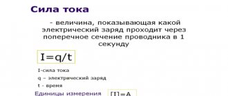
The current in amperes can always be determined by dividing the voltage in volts by the resistance in ohms. Therefore, Ohm's law for a section of a circuit is written as follows:
Any section or element of an electrical circuit can be characterized using three characteristics: current, voltage and resistance.
How to use Ohm's triangle: close the desired value - two other symbols will give the formula for calculating it. By the way, Ohm's law is called only one formula from the triangle - the one that reflects the dependence of current on voltage and resistance. The other two formulas, although they are its consequences, have no physical meaning.
You can also calculate the current in milliamps and microamps, while the voltage should be expressed in volts, and the resistance in kilo-ohms and mega-ohms, respectively.
What kind of lighting do you prefer?
Built-in Chandelier
Other articles about electricity in a simple and accessible presentation:
Ohm's law is valid for any section of the circuit. If it is necessary to determine the current in a given section of the circuit, then it is necessary to divide the voltage acting in this section (Fig. 1) by the resistance of this particular section.
Often, knowing the current and resistance, voltage is determined using Ohm's law. Let's write the formula for determining voltage
The voltage across a section of a circuit is often called voltage drop. This often leads to misunderstandings. Many people think that voltage drop is some kind of wasted unnecessary voltage. In reality, the concepts of voltage and voltage drop are equivalent. Losses and voltage drop - what's the difference?
How to increase DC and AC voltage?
In practice, you can use both purchased and homemade devices. Most homemade circuits can be reproduced with even an average level of training in electrical engineering and circuit design.
Expert opinion
It-Technology, Electrical power and electronics specialist
Ask questions to the “Specialist for modernization of energy generation systems”
Ohm's law for a section of a circuit » School for an electrician: electrical engineering and electronics When the mains voltage fluctuates, instead of the usual LATR, it is advisable to use a stabilizer, where it is included in the form of one of the blocks. Ask, I'm in touch!
AC Voltage Boost
Types of transformers
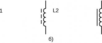
The simplest way to increase alternating voltage is to install a step-up transformer between the mains output and the supplied load. Devices used in practice are divided into two main types. The first is classical transformers, the second is autotransformers. Diagrams of these devices are shown in Figure 2.
A classic transformer contains two windings: a primary or input winding with the number of turns W1, and a secondary or output winding with the number of turns W2. The rule for a transformer is Uoutput = K×Uinput, where K = W2/W1 is the transformation ratio. Thus, in a step-up transformer, the number of turns of the secondary winding exceeds that of the primary.
Features of transformers
The operating efficiency of transformers is increased by using a core made of electrical steel. This component
The inevitable losses due to eddy currents are reduced by the fact that the core is a stacked package of thin profiled insulated plates.
All other things being equal, it is advisable to use a transformer. This is due to the fact that it does not allow direct current to pass through, i.e. provides galvanic isolation of the network from the receiver, allowing for greater electrical safety.
A special feature of the transformer is its reversible nature, i.e. depending on the situation, it can equally successfully perform the functions of a step-up and step-down device. The only serious limitation is the need to comply with the normal operating modes of the primary and secondary windings.
Laboratory autotransformers LATR
The strength of the autotransformer is the ease of regulating the output voltage by simply moving the current-collecting contact along the winding. Devices that allow this option are known as laboratory autotransformers LATR. They differ in their characteristic appearance due to the presence of a voltage regulator and a voltmeter for monitoring it, Figure 4.
LATRs are in demand not only in laboratories. They are widely used in garages, garden plots and other places where, due to overload and line wear, the voltage in the outlet is below the minimum permissible.
When the mains voltage fluctuates, instead of the usual LATR, it is advisable to use a stabilizer, where it is included in the form of one of the blocks.
Expert opinion
It-Technology, Electrical power and electronics specialist
Ask questions to the “Specialist for modernization of energy generation systems”
Physics | Great children's encyclopedia | 2I. SU Angle β characterizes the degree of inclination of the straight graph to the abscissa axis I n, that is, it characterizes the rate of voltage drop with increasing load current. Ask, I'm in touch!
Option 1
1. In 20 minutes, an electric charge of 960 C passes through the iron. Determine the current strength in the iron.
1) 0.6 A 2) 0.8 A 3) 48 A 4) 1920 A
2. The figure shows a graph of current versus voltage on one section of the TV. What is the resistance of this section?
1) 250 kOhm 2) 0.25 Ohm 3) 10 kOhm 4) 100 Ohm
3. If the voltage between the ends of the conductor is increased by 2 times, and its cross-sectional area is reduced by 2 times, then the strength of the current flowing through the conductor
1) will increase by 2 times 2) will decrease by 2 times 3) will not change 4) will increase by 4 times
4. The resistance of the circuit section shown in the figure is equal to
1) 3 Ohm 2) 5 Ohm 3) 8 Ohm 4) 21 Ohm
5. The plugs on some household electrical appliances are labeled “6 A, 250 V.” Determine the maximum permissible power of electrical appliances that can be turned on using such plugs.
1) 1500 W 2) 41.6 W 3) 1.5 W 4) 0.024 W
6. What is the time it takes for current to pass through a conductor if, at a voltage at its ends of 120 V, 540 kJ of work is done? Conductor resistance 24 Ohms.
1) 0.64 s 2) 1.56 s 3) 188 s 4) 900 s
7. Establish a correspondence between physical quantities and the formulas by which these quantities are determined. For each position in the first column, select the corresponding position in the second.
PHYSICAL IMPORTANCE
A) Current B) Voltage C) Resistance
FORMULA
1) A/q 2) I2R 3) ρl/S 4) IUt 5) q/t
Write down the selected numbers under the corresponding letters.
8. Using a boiler with an efficiency of 90%, 3 kg of water was heated from 19 °C to boiling in 15 minutes. What current did the boiler consume in a 220 V network? The specific heat capacity of water is 4200 J/(kg °C).
DC Voltage Boost
The general principle of increasing DC voltage by an arbitrary number of times
The block diagram of such a converter is shown in Figure 5.
Certain types of schemes differ from each other:
- the shape of the signal taken from the output of the generator (sinusoidal or close to it, sawtooth, pulse, etc.);
- the principle of increasing the generated voltage (transformer, multiplier);
- type of rectification and smoothing of voltage before applying it to the output of the device.
Microelectronic element base is available for sale, which allows you to assemble converters of this type even if you have the basic skills of a radio assembler.
Multipliers
Multipliers are used in cases where it is necessary to obtain a constant voltage from an alternating input voltage, which is a multiple of the input voltage.
There are a large number of multiplier circuits. One of them is shown in Figure 6.
The multiplication factor can be increased by increasing the number of cascades.
Rice. 7. Another example: 6 and 8 times multiplier Fig. 8. Voltage quadrupler
Option 3
1. Lightning discharge time is 3 ms. The current strength in the lightning channel is about 30 kA. What charge passes through the lightning channel?
1) 90 C 2) 0.1 µC 3) 90 kC 4) 0.1 µC
2. The figure shows a graph of the current in a conductor versus the voltage at its ends. What is the resistance of the conductor?
1) 0.25 Ohm 2) 2 Ohm 3) 8 Ohm 4) 4 Ohm
3. If the voltage between the ends of the conductor is reduced by 2 times, and its length is increased by 2 times, then the strength of the current flowing through the conductor
1) will not change 2) will decrease by 4 times 3) will increase by 4 times 4) will increase by 2 times
4. The resistance of the circuit section shown in the figure is equal to
1) 9 Ohm 2) 8 Ohm 3) 4 Ohm 4) 3 Ohm
5. On the body of the electric drill there is a sign with the inscription: 220 V, 500 W. Find the current consumed by the electric drill when plugged into the network.
1) 55,000 A 2) 2.27 A 3) 1.14 A 4) 0.88 A
6. How much work will be done by the electric current within 2 minutes if the current in the conductor is 4 A and its resistance is 50 Ohms?
1) 1600 J 2) 96 kJ 3) 24 kJ 4) 400 J
7. Establish a correspondence between physical quantities and the formulas by which these quantities are determined. For each position in the first column, select the corresponding position in the second.
PHYSICAL QUANTITY
A) Current B) Voltage C) Resistance
FORMULA
1) ρl/S 2) I2R 3) A/q 4) q/t 5) IUt
Write down the selected numbers under the corresponding letters.
8. The boiler heats 1.2 kg of water from 12 °C to boiling in 10 minutes. Determine the current consumed by the boiler if it is designed for a voltage of 220 V. The efficiency of the boiler is 90%. The specific heat capacity of water is 4200 J/(kg °C).
Examples of problems using Ohm's law for a closed circuit
A rheostat with a resistance of 4 Ohms is connected to an EMF source of 10 V and an internal resistance of 1 Ohm. Find the current in the circuit and the voltage at the source terminals.
- ε = 10 V
- r = 1 Ohm
- R = 4 ohm
- I – ?
- U – ?
- Let's write Ohm's law for a closed circuit - I=ε/(R+r) .
- We find the voltage drop at the source terminals using the formula U=ε-Ir=εR/(R+r).
- Let's substitute the given values and calculate I=(10 V)/((4+1)Ohm)=2 A, U=(10 V∙4Ohm)/(4+1)Ohm=8 V.
- Answer: 2 A, 8 V.
When a resistor with a resistance of 20 Ohms was connected to a battery of galvanic cells, the current in the circuit was 1 A, and when a resistor with a resistance of 10 Ohms was connected, the current became 1.5 A. Find the emf and internal resistance of the battery.
Lesson 8. alternating electric current – Physics – 11th grade – Russian electronic school
In this article we will look at how to increase the DC and AC voltage and how to do it correctly.
Expert opinion
It-Technology, Electrical power and electronics specialist
Ask questions to the “Specialist for modernization of energy generation systems”
How does current change when voltage changes? Best answers to questions For such devices, the current-voltage characteristic will not be a straight line passing through the origin of coordinates, but will be either a curve or a broken line. Ask, I'm in touch!
Increasing the current in a circuit: several possible options
Various categories of users quite often have situations in which it is necessary to make certain changes to the parameters of the current one. Previously assembled and tested network. It is possible to increase the strength of direct current flowing in a closed loop of a particular circuit; there are even several different options and methods of practical action. But it is important to understand that this can be done safely only if measures are taken to protect electrical appliances. To do this you will need to use a number of special devices.
1 way
The simplest solution to the problem is to increase the voltage supplied to the input of the circuit. So, for example, if a voltage of 3 volts is set in a circuit with a resistance of 20 Ohms, then the current here, according to Ohm’s law, is 0.15 A. If you introduce an additional device into the circuit, another power source with the same U = 3V, then and the current will double and be 3A.
Method 2
Reducing resistance. If we reduce the load in the circuit by half, from 2 Ohms to 1 Ohm, we get the following result: 2 V: 1 Ohm = 2 A. Thus, doubling occurs automatically by a similar amount (if there are no other sources, consumers and devices in the circuit that can influence the efficiency of the circuit and its parameters). Naturally, if you increase the resistance, the current will decrease.
3 way
We change the parameters of the conductors. To do this, you will need to assemble a circuit that will include: source, consumer and wires. The parameters of the conductors also play an important role in the formation of current strength in the circuit. First you need to understand what materials the original conductors are made of; using special tables, knowing the cross-sectional size, you can establish exact indicators. An increase in current can be achieved by reducing resistance, and for this you can select conductors made from other metals.
You can also adjust the parameters by shortening the length of existing conductors. If it is not possible to double the current, then in addition to changing the parameters of the conductors, you will need to make other decisions from those described above.
It is also possible to increase the cross-section of the conductor, which will lead to a parallel increase in current.
An interesting option for increasing the strength of direct current using a magnet, for which it is necessary to change and increase the magnetic induction of the field within which this conductor is located.
Electric circuit and Ohm's law
Three quantities—voltage, electric current, and resistance—can be clearly represented in an electrical circuit. In the simplest case, it consists of a constant voltage source and a resistor. The resistor is connected to a voltage source, and for simplicity, let's assume that the resistance of the wires is 0 Ohm.
Rice. 1. Electric circuit
Direction of electric current.
In electrical engineering, current flows from plus to minus (see Figure 1). In other words, as soon as a closed circuit occurs, current begins to flow from the positive pole to the negative pole of the voltage source. We talk about a closed circuit when the two poles of the voltage source are connected to each other by resistance.
How and with what to measure current and voltage?
There are two ways to determine current and voltage. On the one hand, they can be determined arithmetically using Ohm's law for a section of a circuit. On the other hand, two variables can also be determined by measurement.
However, for the arithmetic determination of current or voltage, two other quantities must be known (voltage and resistance or current and resistance).
On the other hand, the metrological method also works with any electrical circuit. To do this, you need to insert an ammeter and a voltmeter into the electrical circuit. They are used to measure current and voltage. But Ohm's law also applies here because resistance cannot be measured directly, but it can be calculated when the current and voltage values are measured.
So, the current is measured with an ammeter, which is connected in series to the consumer (resistor, incandescent lamp, etc.), through which the current must be determined. In the circuit diagram it is shown as A inside a circle (see Figure 1). The ammeter has a very low internal resistance so as not to affect the current that must flow through the consumer. Ideally, the internal resistance of the ammeter is taken to be 0 ohms and is therefore simply dropped.
Voltage is measured using a voltmeter, which measures the potential difference between its two connection points. On the electrical diagram it is indicated by the letter V inside a circle (see Figure 1). Unlike an ammeter, a voltmeter is connected in parallel to the load on which the voltage is measured. Adding a voltmeter in parallel with some consumer (for example, a resistor) creates another “bypass” path for the current, which dramatically changes the parameters of the circuit. To avoid these undesirable consequences, it is necessary to use voltmeters with the highest possible resistance.
Current-voltage characteristic (VAC).
The current-voltage or UI of a resistor can be recorded by applying various voltages to it and then measuring the current. Typically, with ohmic resistance, one measuring point is sufficient, which is then connected to the origin of the coordinate system. However, in practice, for control purposes, a series of measurements with three measurement points is performed.
These measurement points are then marked in the coordinate system and connected. Voltage is plotted along the abscissa axis, and current is plotted along the ordinate axis. An example of a current-voltage characteristic is shown in the figure below.
Volt-ampere characteristics
The I-V curve can be used to determine the current through a resistor at a specific voltage.

