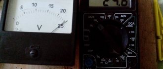
A voltmeter is a measuring instrument used to determine the voltage level in an electrical circuit when connected in parallel to the part of the circuit being measured.
When analyzing the operation of electrical and electronic circuits or when trying to understand why a circuit is not performing as expected, you will eventually have to use a voltmeter to measure different voltage levels. Voltmeters used to measure voltage come in many shapes and sizes, analog or digital, or as part of a digital multimeter, which is most commonly used today.
Voltmeters can also be used to measure DC voltage as well as sinusoidal AC voltage, but introducing a voltmeter as a measuring device into a circuit may disrupt its steady state.
As the name suggests, a voltmeter is an instrument used to measure voltage (V), which is the potential difference between any two points in a circuit. To measure voltage (potential difference), a voltmeter must be connected in parallel with the component whose voltage you want to measure.
Voltmeters can be used to measure the voltage drop across a single component or power source, or to measure the sum of the voltage drops across two or more points or components in a circuit.
For example, if you connect a voltmeter to the terminals of a fully charged car battery, it will read 12.6 volts. That is, between the positive and negative poles of the battery there is a potential difference of 12.6 volts. Thus, voltage, V, is always measured across or parallel to a circuit component.
The most basic type of analog DC voltmeter is the permanent magnet moving coil (PMMC) voltmeter, also known as a Darsonval mechanism.
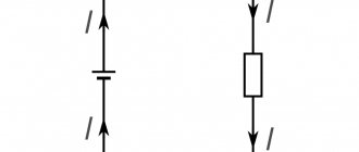
This type of analogue meter is a current measuring instrument (galvanometer) that can be configured to act as a voltmeter or an ammeter, the main difference being the way they are connected to the circuit.
A moving coil mechanism uses a stationary permanent magnet and a coil of very thin wire that can move (hence the name moving coil) in the magnetic field of the magnet.
When connected to a circuit, an electric current flows through the coil, which in turn creates its own magnetic field (electromagnetism), which reacts to the magnetic field created by the surrounding permanent magnet, causing the coil to move.
Since the galvanometer responds to an internal current, if we know the internal resistance of the coil (wound with copper wire), we can simply use Ohm's law to determine the corresponding potential difference to be measured.
Design of a permanent magnet moving coil measuring instrument
The amount of movement of the electromagnetic coil, called "deflection", is proportional to the amount of current flowing through the coil required to create the magnetic field needed to deflect the needle.
Typically a pointer, or needle, is connected to the coil so that the movement of the coil causes the pointer to deflect on a linear scale to indicate the quantity being measured, the angle of deflection being proportional to the input current. Thus, the galvanometer needle moves in response to the current.
Typically, thin, clock-type coil damping springs are used to control the angle of deflection, preventing oscillations or rapid movements that could damage the pointer, and also holding the coil motion at rest when no current is flowing through the coil.
Typically the needle moves between zero on the left and full scale deviation (FSD) on the far right of the scale. Some measuring mechanisms have a spring-centered pointer with the zero rest position in the middle of the scale, allowing the pointer to be moved in both directions. This is convenient when measuring voltage of any polarity.
Although this PMMC meter mechanism responds linearly to current flow in a moving coil, it can be adapted to measure voltage by adding a resistance in series with the movement of the coil. The combination of series resistance with moving coil motion produces a DC voltmeter that can give accurate results once calibrated.
Wiring type and its parameters
At home, you most often have to deal with alternating current, much less often with direct current. Typically, direct current is measured in batteries and batteries; house wiring always runs on alternating current. Even if the electrical network is powered by batteries (a backup power source, the main one in the absence of a centralized power supply), it must contain an “adapter” - a device that converts direct current into alternating current.
When figuring out how to measure current with a multimeter, you need to clearly understand: to work with direct current, use the DCA (A-) segment of the multimeter, for measuring alternating current, use the ACA (A) sector
). The designations are associated with abbreviations of English terms: direct current amperage (DCA) and alternating current amperage (ACA) is the designation of alternating current on a multimeter.
Typically, multimeters allow you to measure microcurrents - up to 200 mA - and stronger ones (up to 10A). Devices that allow measurements in more powerful electrical networks have an additional socket for a plug (probe) marked 20A. Typically, in models with four connectors, two are designed to measure current in different ranges, one is for other measurements (voltage, resistance).
The COM (COMMON) connector, common (universal) for all types of measurements, is intended for the negative (black) probe of the multimeter.
Thus, to measure current with a multimeter, you need to connect the black probe to the COM connector, and the red probe to the socket for checking microcurrents or ordinary currents. For sockets and switches, the device regulator is set to the alternating voltage sector, for batteries and batteries - constant. If the level is unknown in advance, the highest value allowed by the device is selected.
Important: if no energy-consuming device is connected to the outlet (on the switch), the electrical circuit is open and there is no current in it. Measuring the current directly in the socket or on the contacts of the switch is useless and dangerous! This causes a short circuit.
Voltage measurement
When electric charges are in equilibrium, the voltage between any two points in a circuit is zero, but if current flows through the circuit (charge movement), then a voltage will exist between two or more different points in the circuit.
Using a galvanometer, we can measure not only the current flowing between two points, but also the voltage difference between them, according to Ohm's law, since these quantities are proportional to each other. Thus, using a graduated voltmeter, we can measure the potential difference between any two points in a circuit.
But how do you convert a device that handles current into one that can be used to measure voltage? The deflection of a permanent magnet moving coil meter is proportional to the current passing through its moving coil.
If its full-scale deviation (FSD) is multiplied by the internal resistance of the moving coil, the meter can be made to read voltage instead of current, thus turning a permanent magnet moving coil meter into a DC voltmeter.
However, due to the moving coil design, most PMMC meters are very sensitive instruments that can have full-scale deflection current IG ratings as low as 100 µA (or less). If, for example, the resistance of the moving coil RG is 500Ω, then the maximum full-scale voltage we could measure is only 50mV (V = I*R = 100µA x 500Ω).
Therefore, in order for the sensitive moving coil of a PMMC voltmeter to measure higher voltage values, we need to find a way to reduce the voltage being measured to a value that the meter can withstand, and this is achieved by installing a resistor called a multiplier in series with the internal resistance of the meter coil.
Let's say we want to use our 100 µA, 500 ohm galvanometer to measure voltage in a circuit up to 1.0 volts. Obviously, we cannot connect the meter directly to measure 1 volt because, as we saw earlier, the maximum voltage it can measure is 50 millivolts (50 mV). But, using Ohm's law, we can calculate the value of the series resistor RS that is needed to obtain full-scale motion of the meter when measuring a potential difference of one volt.
Thus, if the current at which the galvanometer gives full scale deflection is 100 µA, then the required series resistance RS is calculated as 9.5 kΩ. Thus, a galvanometer can be converted into a voltmeter by simply connecting a sufficiently large resistance in series with it, as shown in the figure.
EMF and voltage, or what a voltmeter measures
Nowadays, in our home, at work and on the street, everything depends on electricity. We constantly use electric current - alternating and direct. Current is the directed movement of charge carriers under the influence of an electric field. So, voltage, or potential difference, is a physical quantity equal to the work an electric field does when transferring a unit charge from one place to another.
Read also: Do-it-yourself amplifier for a car subwoofer
When we talk about a galvanic cell, where internal chemical processes occur, or a turbine, which is rotated by the waters of a river, it is incorrect to use the expression “potential difference”, because the work of moving a charge is carried out by external forces of a chemical or mechanical nature. For such cases, the concept of electromotive force (EMF) is used. It is this indicator that is written on batteries that are sold at the checkout in a store, and when we connect a voltmeter to the terminals without connecting a circuit with a load, we will see exactly it.
Both EMF and voltage are measured in volts. Formally, the dimension of this unit is explained as follows: the potential difference between points A and B is equal to 1 V, if to move a charge of 1 coulomb from point A to point B we spend 1 joule of work. From this unit - volt - comes the everyday name for voltage when it is measured: voltage.
Example of voltmeter No1
The PMMC galvanometer has an internal coil resistance of 100Ω and produces a full-scale deflection of 200mV. Find the multiplier resistance required for the meter to give total deviation when measuring 5 volts DC.
Therefore, the required series resistance is 2.4kΩ.
We can use this method to measure any voltage value by changing the value of the multiplier resistors as needed as long as we know the current or voltage full scale deviation (FSD) values (IFSD or VFSD) of the galvanometer. Then all we have to do is relabel the scale to count from zero to the new measured voltage value.
This simple series-connected voltage divider circuit can be expanded to a number of different "multiplier" resistors, allowing the voltmeter to be used to measure a number of different voltage levels with the flick of a switch.
Voltmeter. Kinds. Device. Job. Application. Peculiarities
A voltmeter is a measuring device for reading the level of electrical voltage. It is connected in parallel to the load or directly to the voltage source (U). The unit of measurement for voltage is Volt (V). The device has high resistance. The larger it is, the better and more accurate it is. This reduces the impact on the measured circuit, and makes it possible to read voltage data with minimal error.
Design of a multi-range voltmeter
Our simple DC voltmeter described above can be expanded by using a number of series resistances, each rated for a specific voltage range, which can be selected one at a time using a single multi-pole switch, allowing our analog voltmeter to measure a wider range of voltage levels in one move .
This type of voltmeter configuration is called a multi-range voltmeter, where ranges are selected based on the number of switch positions, such as 4-position, 5-position, etc.
How to measure current with a multimeter on a battery
For low-power batteries and batteries, current measurement is simpler than for an alternating current network.
In this case, measuring the current strength with a multimeter is carried out on the “direct current” measurement range; the value is set taking into account the battery markings or, in the absence of data, to the maximum permissible value of the range.
Measurements, as in the case of alternating current, are made in the presence of a “load”; the contacts are connected in parallel.
A circuit for measuring current in a car battery is given below. Important: The leakage current is measured here.
Direct configuration multi-range voltmeter
In this voltmeter configuration, each multiplier resistor RS of the multi-range voltmeter is connected in series with the meter as before to obtain the desired voltage range. So, if we assume that our 50mV FSD meter is required to measure the following voltage ranges: 10V, 50V, 100V, 250V and 500V, then the required series resistors are calculated in the same way as before:
Reducing the circuit of a direct multi-range voltmeter from:
While this direct voltmeter configuration works very well for reading our voltage range, the multiplier resistor values needed to get the meter's correct FSD for the calculated ranges may produce resistor values that are not the standard preferred values, or require resistor soldering to obtain an accurate value.
The values we calculated from 99.5kΩ to 4.9995MΩ are not commonly accepted resistor values, so we need to find a variation on the voltmeter design above that will use more commonly available resistor values.