At many enterprises there is a need to measure various parameters, change the condition of parts, and various structures. To solve these problems, strain gauge sensors are used. They convert the amount of deformation into an electrical signal. This is obtained by reducing or increasing the resistance of the sensor during deformation, violating the geometry of the sensor from compression or stretching. As a result, the deformation value is determined.
A resistive converter is the main component of high-precision devices and instruments. The sensor is made from a sensitive strain gauge, which is a thin aluminum wire or foil. As a result of deformation, the resistor changes its resistance and sends a signal to the indicator.
Kinds
There are many types of strain gauges used in different industries.
- Devices that measure force and load.
- Pressure control.
- Acceleration meters.
- Displacement meters.
- Torque control sensors for machine tools and car engines.
Sensor models are varied, but the most commonly used is a weight detection sensor, which is manufactured in various versions: washer, barrel, S-shaped. Based on the purpose, the required execution is selected.
Strain gauges have a classification, both by shape and by design features, which depends on the type of sensing element.
The following types of sensors are used:
- From foil.
- Film.
- Made of wire.
Foil sensor
It is used in the form of gluing to a surface. The sensor design consists of 12 micron foil tape. Partially the film is dense, the rest is lattice-like. This design is distinctive in that auxiliary contacts can be soldered to it. Such sensors are easily used at low temperatures.
Film sensors
made by analogy with foil ones, except for the material. These types are made from strain-sensitive films that have a special coating that increases the sensitivity of the sensor. These meters are convenient to use for monitoring dynamic loads. Films are made of germanium, bismuth, titanium.
Wire version
The sensor can measure precise loads from hundredths of a gram to tons. They are called single-point, since the measurement does not take place over an area, but at one point, unlike foil and film sensors. Wire sensors can be used to control tension and compression.
Operating principle of strain gauges
Strain gauges are a structure made of a strain gauge with a contact on the panel. It comes into contact with the body to measure. The principle of the sensor operation is to act on the sensitive element of the part being examined. To connect the sensor to power, electrical taps connected to the sensitive plate are used.
There is a constant voltage in the contacts. The part is placed on the strain gauge through the substrate. The weight of the part breaks the chain by deformation. The strain is modified into a current signal.
The load cell measurement bridge makes it possible to measure minimum loads, thereby expanding the applicability of the device. The sensor bridge connection diagram is based on Ohm's law. If the resistances are equal, then the current passing will be the same. The action from outside is called “external factor”, the change in signal is called “internal factor”. Then we can say that the principle of operation of the sensor is to determine an external factor using an internal one.
In everyday life, strain gauges work in scales. Strain gauges are connected to the operating surface of the scales. The scales are connected to power via batteries.
This control device has high accuracy. The error of the sensitive elements is less than 0.02%, which is a high figure. There are devices with sensitivity much higher than this. Their work is based on controlling the action of force. The pressure force value is directly proportional to the converted strain gauge signal.
Operating principle of force sensors
Force sensors, in other words dynamometers, are part of devices that measure weight. Their absence makes it impossible for the system to automate technical processes in production. They are used in agriculture, construction, and metallurgy.
The work is based on the change in strain in the signal. In operation, many different phenomena occur, which lead to several types of strain gauges:
- Tactile.
- Resistive.
- Piezoresonant.
- Piezoelectric.
- Magnetic.
- Capacitive.
Tactile sensors
This type of sensor is the newest, appearing after the advent of robotics. Tactile sensors are divided into: force, touch, and slip sensors. The first two determine the strength and differ in signal. They differ from others in their small thickness due to the use of special materials that have strength, elasticity, and flexibility.
The design consists of 2 plates (1 and 2). Between them there is a gasket (3) with cells made of insulating material. One wire is connected to the top plate, the second to the bottom plate. When a force is applied to the upper plate, it bends and locks with the lower one. The voltage drop across the resistor is the output signal.
Resistive strain gauge
This is a widely used type of sensor, since the operating force range is from 5 N to 5 MN and is used for different loads. Its advantage was the linearity of the output signal. The working element is a strain gauge consisting of a wire on a flexible substrate.
1 - Substrate 2 - Sensing element 3 - Contacts
The sensor is glued to the object being measured. Under the influence of deformation, the resistance of the resistor and, accordingly, the supply signal changes.
Piezoresonance strain gauge
This type of sensor uses two effects: inverse and forward. The sensitivity element of the sensor is a resonator. The reverse piezoelectric effect is caused by the voltage that causes charges, this is called the direct piezoelectric effect.
Oscillations of the resonator cause resonant oscillations. Piezoresonant sensors are connected according to different schemes. The figure shows a circuit with a frequency generator and a resonance filter. The force acts on the resonator, changing the filter frequency settings, which determine the output voltage.
Piezoelectric strain gauges
The work is based on the direct piezoelectric effect. The following materials have it: crystals of barium titanate, tourmaline, quartz. They are chemically stable, have high strength, and their properties depend little on the ambient temperature.
The essence of the effect is the action of force on the material. Charges of different polarities arise, the magnitude of which depends on the force. The sensor consists of a housing, two piezoelectric plates, and leads. When exposed to force, the plates are compressed, causing a voltage to be applied to the signal amplifier.
Such strain gauges are used to monitor dynamic forces.
Magnetic strain gauges
Magnetostriction is a fundamental phenomenon for the operation of this type of sensor. This effect changes the geometry of dimensions in a magnetic field. Changing the geometry changes the magnetic properties, which is called the magnetoelastic effect. When the force is removed, the properties of the body return.
This is determined by a change in the arrangement of atoms in a crystal lattice in a magnetic field or under the influence of force. In our version, the inductor is located on a ferromagnetic core. The force causes the core to deform, resulting in a state of tension.
Changing the core results in a change in its permeability, and, consequently, the magnetic resistance and inductance of the coil changes.
Sensors with two coils have become widely used. The primary is powered by a generator, and an EMF is generated in the secondary. During deformation, the magnetic permeability changes. As a result, the EMF of the 2nd winding changes.
Capacitive sensors
This is a parametric type of sensor, which is a capacitor. The larger the plate area, the greater the capacity. And the larger the gap between the plates, the smaller the capacity.
This property is used for the design of capacitive sensors. To make measurements convenient, capacitance is converted into current. To do this, different connection schemes are used.
Typically, a variant with compression of the dielectric between the plates is used.
Advantages of strain gauges
- Increased measurement accuracy.
- Combined with voltage measurements, no distortion of measurement data. This convenience is indispensable when using sensors in transport or in critical situations and conditions.
- Small sizes make it possible to use them in any size.
The disadvantages of strain gauge sensors include a decrease in sensitivity during sudden temperature changes. To obtain accurate results, it is recommended to control measurements at room temperature.
Connecting strain gauges
You can easily connect strain gauges yourself using the diagram. Before purchasing strain gauges, determine the length of the connection cable. If a short cable is extended in length, the measurement accuracy of the indicator will be significantly less. This parameter can be optimized using the SE 01 controller, which acts instead of an amplifier.
If different indicators are used in the design of the scales, then they are connected in a parallel circuit using special boxes. Sensor conductors must be grounded, regardless of the type of power supply. Grounding is installed at a common point. A branch box is used for these purposes.
Next, the correct connection according to the sensor diagram, reliability of contacts and grounding are checked. The device is installed using a shielded cable. It suppresses interference; auxiliary modules are not needed when using it. The converter is connected to the dispenser in a similar way.
In many industries, it is necessary to measure the size of the deformation. For such purposes, a pressure strain gauge is used, which helps convert the level of deformation into a certain value. Thanks to this, its value can be determined.
What is a strain gauge?
A strain gauge, in accordance with clause 2.1.2 of GOST 8.631-2013, is a weighing element that responds to changes in the magnitude of physical impact (force) and converts it into an electrical signal. In fact, this is a resistor that changes the ohmic resistance parameter in relation to the applied force. In practice, they are widely used to measure mass and load in weighing systems. Depending on the scope of application, various types of strain gauges are used, differing both in their operating principle and design features.
Load cell diagnostics
Strain gauges are the main primary device for converting the physical quantity of weight into a standardized electrical signal. Which is subsequently processed by secondary converters (weight indicator, weight processor, analog-to-digital converter, etc.). The load cell is the most vulnerable component of a weighing system. During operation, load cells are affected by: aggressive environment, shock dynamic loads, electrostatic effects (welding), vibrations, etc. Therefore, during periods of maintenance, before installation on scales, as well as in emergency cases, there is a need to diagnose strain gauges. Next, we will consider an algorithm for checking the condition of the strain gauge.
General recommendations
Carefully check the general technical condition of the weight measurement system:
- presence of a grounding loop (shunt), tightening of threaded connections;
- checking the absence of traces of corrosion, damage to strain gauges, installation units, and load receptors;
- checking summing boards; weight indicator on the strain gauge simulator;
- testing the weight indicator, connecting to the strain gauge simulator;
- inspection of the condition of cable products, tightness of the cable entry on the strain gauge;
To perform diagnostics you must:
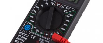
- ideally, a calibrator or volt-ohmmeter with a measurement limit of ≤0.5Ω and ≤0.1 mV (in extreme cases, a high-quality multimeter) to measure the zero balance and integrity of the strain gauge bridge;
- megohmmeter 1000 MΩ no more than 50V DC, for measuring insulation resistance;
- a lifting device (jack, crane, etc.) necessary to lift the load receptor and release the load cell from the load;
- prepare a table to record the values taken during measurement;
Diagnostic algorithm and troubleshooting of the strain gauge:
The algorithm proposed below shows possible malfunctions and a method for troubleshooting. Next, we will take a closer look at each of the tests and the sequence of checking the load cell.
Test 1: Checking zero balance
Measuring zero balance is necessary to check the condition of the load cell in an unloaded state; for this, the load cell is removed from the installation unit and all applied load is removed from the load cell. Next, connect a 10 V power source to the excitation circuit of the strain gauge, a signal in mV is taken from the output circuit and compared with the value in the calibration sheet. Example: with a strain gauge sensitivity of 2mV/V and a power supply of 10V, the zero balance voltage corresponds to +- 0.02 mV. If the values of the output signal differ significantly from the passport values, one can judge the deformation of the elastic element of the strain gauge, as well as the violation of the insulating layer of the strain gauges.
Test 2: Insulation Resistance Test
This is done by connecting a megger to the strain gauge cable and checking for leakage current between the strain gauge body and live parts. A low insulation resistance value of less than 1 kOhm indicates a short circuit (short circuit). The normal value is 5Mohm. A short circuit can occur between the load cell housing and live parts, as well as in the cable. With short circuit in the cable and leakage current appears, the cable can be replaced if the design of the strain gauge allows this.
Test 3: Checking the integrity of the strain gauge bridge (Wheatstone bridge)
The integrity of the bridge is verified by measuring the input and output resistance, as well as the balance resistance of the bridge. Disconnect the sensor from the box or meter. Input and output resistances are measured with an ohmmeter connected to each pair of input and output wires of the strain gauge. Next, the input and output resistance are compared with the values in the calibration certificate or with the technical specification of the original strain gauge. The bridge balance resistance is measured by connecting an ohmmeter to each pair of cable terminals in turn. The resistance value between pairs should not differ by more than 1-2 Ohms.
The difference between the input and output resistance of the strain gauge from the nameplate values indicates a malfunction of the strain gauge bridge; the appearance of unbalance resistance means the strain gauge is inoperable and needs to be replaced. Such malfunctions appear, as a rule, as a result of electrical influence (welding, static field, electrical breakdown), physical (impacts, twisting, lateral loads), and thermal.
Test 4: Test under load
The sensor must be connected to a weight indicator or to a device with a stable power source of at least 10V. Using a millivoltmeter connected to the output of the strain gauge, the sensor is loaded and the output signal readings are recorded; when the load is removed, the output signal readings should return to the original ones. Be extremely careful not to overload the load cell! If during the test the readings differ under a constantly applied load and do not return to the original values, it can be judged that the contact in the adhesive layer between the strain gauges and the elastic element is broken. The load cell requires replacement.
Design
As an example, let's consider the simplest version of a strain gauge, where a strain gauge acts as a sensitive element. Structurally, it can be represented in the form of a thin elastic wire or film distributed over the controlled surface.
The operation of a strain gauge is based on Hooke's law, which states that the change in electrical resistance relative to the initial position of the element is proportional to the elongation or compression of the sensor. Guided by this principle, the proportionality coefficient is determined:
K = Δl / l = ΔR / R
Where:
- K – proportionality coefficient;
- Δl is the magnitude of the change in length during deformation;
- l – length of the measured element at rest;
- ΔR – change in resistance value during deformation;
- R – resistance value of the strain gauge in the normal position.
In practice, this is implemented as follows (Figure 1):
Rice. 1. Strain gauge device
When at rest, the strain gauge tracks have a certain cross-section and conductor length. The resistance of the entire resistive element of the strain gauge will be determined by the formula:
R = (ρ*l)/S, where
- ρ is the resistivity of the material; as a rule, constantan is used as a metal with constant resistivity;
- l – length of the strain gauge conductor;
- S – cross-section of the strain gauge conductor.
Thus, if the strain gauge is extended, the length of the conductive paths increases and the cross-section decreases. As a result, the ohmic resistance of the strain gauge will increase. When compressed, the reverse process will occur - the length of the conductive elements will decrease, and their cross-section will increase. As a result of compression, the resistance of the strain gauge will decrease, which is the basis of its operating principle.
What is strain gauge and why are strain gauges needed?
Strain measurement (from the Latin tensus - tense) is a method and technique for measuring the stress-strain state of the measured object or structure. The fact is that it is impossible to directly measure mechanical stress, so the task is to measure the deformation of an object and calculate the stress using special techniques that take into account the physical properties of the material.
The operation of strain gauges is based on the tensoelectric effect - this is the property of solid materials to change their resistance under various deformations. Strain gauges are devices that measure the elastic deformation of a solid and convert its value into an electrical signal. This process occurs when the resistance of the sensor conductor changes when it is stretched and compressed. They are the main element in instruments for measuring the deformation of solid bodies (for example, machine parts, structures, buildings).
Principle of operation
In most cases, the strain gauge does not operate from a single strain gauge, but includes a bridge measuring circuit. This principle is called the Wheatstone bridge and is implemented as follows (Figure 2):
Rice. 2. Operating principle of the strain gauge
As you can see in the figure, four strain gauges are included in the bridge arms, which are located on a flexible substrate, which provides them with elastic deformation during measurements. All resistive elements of the strain gauge are selected to be equivalent, which ensures that the output at rest has a zero potential difference at points + S and – S. This means that in an unloaded ideal strain gauge no current will flow in the output circuit of the measuring device. In a real device, there is still a current load due to design differences in resistive parts and temperature fluctuations.
As soon as a mechanical load is applied to the measuring element of the device, the flexible base is deformed, which changes the operating parameters of all resistors in the strain gauge bridge circuit. In most cases, strain gauges are compressed and stretched in pairs (Figure 3):
Rice. 3. Impact of load on the load cell
As you can see, in the figure two resistors are compressed, and the other two are stretched, resulting in distortion of the bridge. The electrical circuit becomes unbalanced and electric current begins to flow through the output of the strain gauge. This will be indicated by the deviation of the galvanometer needle or the equipment display responding to changes in the potential difference. As soon as the load ceases to act on the load cell, the flexible plate will return to its original state, and the measuring bridge will again enter a state of equilibrium.
In this example, we looked at the simplest version of a four-wire strain gauge. But in practice, five and six-wire load sensors are also used, depending on the type of specific device.
Types
The scope of application of strain gauges covers a number of devices for various purposes. Therefore, strain gauges of various types are used to measure the magnitude of physical impact. Sensors are divided into types based on several factors.
Rice. 4. Types of sensors according to the shape of the load-receiving base
So, depending on the shape of the load-receiving base, the following are distinguished:
- Cantilever (beam) – installed in some types of scales, when weighing containers, etc.;
- S-shaped - used to measure lifted loads;
- Membrane – used in control systems, high-precision meters, etc.;
- Column – mounted in equipment with a large mass;
Depending on the type of measurement method, all strain gauges are divided into:
- Resistive - the work is based on a strain gauge or a bridge made of them, located on a flexible base. Such a strain gauge is attached to the surface of the meter and responds to mechanical deformations. In accordance with clause 1.1 of GOST 21616-91, they are divided into wire and foil. According to quantity and shape, they are divided into single, sockets, chains, and membrane sockets.
- Tactile - consist of two conductors, between which there is a perforated dielectric film. When pressed, the conductors push through the soft dielectric and provide some conductivity, which changes the resistance value. By type of measurement there are touch, slip, and force sensors.
- Piezoresonant - based on semiconductor elements, in such strain gauges the real signal is compared with the reference one.
- Piezoelectric - based on the intrinsic voltage of the electron output of some semiconductor crystals. When a force is applied to the crystal, the magnitude of the charges also changes, which is transmitted to the measuring element of the strain gauge.
- Magnetic - use the property of magnetic conductors to change the value of magnetic permeability depending on physical parameters. When the core is compressed or stretched, the electromagnetic flux generated by the coil will change. As a result, the inductance of the strain gauge will also deviate from the reference state.
- Capacitive - use the effect of a variable capacitor, in which the capacitance will increase as the distance between the plates decreases. And as the distance increases or the area of the plates decreases, the capacity will decrease.
5. Operating principle of a capacitive strain gauge In accordance with clause 1.2 of GOST 28836-90, according to the nature of the applied force, strain gauges can be divided into those that respond to compression, tension and universal ones.
Connection diagrams
In practice, various methods are used to connect a strain gauge to a common circuit. The simplest option is a four-wire connection diagram, which is shown in Figure 6 below:
Rice. 6. Four-wire connection diagram
In this case, the connection diagram implies strict adherence to the color marking of the wires: red and white for supplying voltage, and black and green for picking up the received signal. The fifth wire is used to ground the equipment frame; some models use a shield to eliminate interference. This option is used for power sensors and low-current equipment installed directly at the place of measurement and recording of the result. In practice it can be implemented as follows:
Rice. 7. Practical implementation of a four-wire connection diagram
When the weighing unit is removed from the control unit, a six-wire circuit is used to eliminate the influence of the ohmic resistance of the power wires on the measurement result.
Rice. 8. Six-wire circuit with feedback circuit
The + E and – E pins are used to supply voltage to the load cell. The voltage drop across the wires is taken from the + Sen and – Sen terminals, which is then subtracted from the resulting signal. Contacts + S and – S are used to take readings, the subtraction function is implemented as follows:
Rice. 9. Practical implementation of voltage subtraction
Load cell calibration:
The calibration process is shown in the video:
Code from video for calibration:
Calibration code
/* Set up your scale and start the sketch WITHOUT a weight on the scale Once readings are displayed place the weight on the scale Press +/- or a/z to adjust the calibration_factor until the output readings match the known weight Arduino pin 6 -> HX711 CLK Arduino pin 5 -> HX711 DOUT Arduino pin 5V -> HX711 VCC Arduino pin GND -> HX711 GND */ #include "HX711.h" HX711 scale(A1, A0); // DT, CLK float calibration_factor = -3.7; // this calibration factor is adjusted according to my load cell float units; float ounces; void setup() { Serial
.begin(9600);
Serial
.println("HX711 calibration sketch");
Serial
.println("Remove all weight from scale");
Serial
.println("After readings begin, place known weight on scale");
Serial
.println("Press + or a to increase calibration factor");
Serial
.println("Press - or z to decrease calibration factor");
scale.set_scale(); scale.tare(); //Reset the scale to 0 long zero_factor = scale.read_average(); //Get a baseline reading Serial
.print("Zero factor: ");
//This can be used to remove the need to store the scale. Useful in permanent scale projects. Serial
.println(zero_factor);
} void loop() { scale.set_scale(calibration_factor); //Adjust to this calibration factor Serial
.print("Reading: ");
units = scale.get_units(), 10; if (units < 0) { units = 0.00; } ounces = units * 0.035274; Serial
.print(ounces);
Serial
.print("grams");
Serial
.print(" calibration_factor: ");
Serial
.print(calibration_factor);
Serial.println
();
if( Serial
.available()) { char temp =
Serial
.read(); if(temp == '+' || temp == 'a') calibration_factor += 1; else if(temp == '-' || temp == 'z') calibration_factor -= 1; } }
Code for scales
#include "HX711.h" HX711 scale(A1, A0); float calibration_factor = -3.7; // calibration! float units; float ounces; void setup() { Serial
.begin(9600);
scale.set_scale(); scale.tare(); //Reset to 0 scale.set_scale(calibration_factor); //Apply calibration } void loop() { Serial
.print("Reading: ");
for(int i = 0;i < 10; i++) units =+ scale.get_units(), 10; // average the readings by counting 10 times units / 10; // divide by 10 ounces = units * 0.035274; // convert ounces to grams Serial
.print(ounces);
// send to the port monitor Serial
.print("grams");
Serial.println
(); }
The unit of weight has been changed in the code, the value in the port monitor is in grams, not in ounces.
Purpose
The strain gauge is installed in various devices and devices to monitor the response to physical impact. Today, its scope of application covers a wide variety of industries and the national economy, where it is used for:
- Weight measurements – installed in various types of electronic scales.
- Acceleration definitions – used in vehicle testing.
- Pressure measurements - common in surface finishing, force control, mechanical applications, etc.
- Movement control – records the movement of building elements, foundations, seismological devices, etc.
- Torque measurements - used in the mechanical engineering industry, for maintenance and others.
How to choose?
When choosing a model for measuring any physical effort or weight, you must be guided by the basic parameters of the sensor. These characteristics include:
- Measurement range – determines the limits of the weight load that the strain gauge can record;
- Accuracy class – selected depending on the equipment parameters and requirements for measurement accuracy;
- Connection diagram – depending on the number of connected pins, a four- or six-wire circuit can be used;
- Thermal compensation – for strain gauges where high measurement accuracy is required, it is important to take into account the influence of ambient temperature; thermal compensating elements are used;
- The degree of protection is indicated by the IP index and determines the resistance to dust and moisture on the load cell.
How to check a load cell or diagnose faults in the operation of load cells
The diagnostic parameters of strain gauges indicated in the article refer to products of the VPG group of companies produced under the brands: CELTRON, REVERE TRANSDUCERS, SENSORTRONICS, TEDEA-HUNTLEIGH. When diagnosing strain gauges from other manufacturers, you should use the testing parameters specified in the technical data sheet of the strain gauge being tested.
Load cells are designed to sense force or weight under a wide range of adverse conditions. They are not only the most important part of the electronic weighing system, but also the most vulnerable. Possible causes of failure of strain gauges: - overload - lightning - power surges - exposure to chemicals or moisture - improper installation - vibrations - shock loads These reasons can lead to zero drift, unstable data transmission or no data transmission at all. Trimming the length of the standard strain gauge cable leads to a decrease in the accuracy of readings, since its resistance is taken into account in the total resistance specified in the strain gauge data sheet.
This article examines typical problems during the operation of strain gauges and testing methods to identify points of failure of a complex of weighing equipment.
Carefully check the integrity of the weighing system: • Check the system for shorts (may be caused by contamination, mechanical damage) • Check for damage, corrosion or significant wear on the platform metal structures. • Check cable connections to the junction box and weighing terminal. • Check the functionality and accuracy of the indicator or weighing terminal on a working load cell. Perform a visual inspection of the weighing equipment before performing the tests described below. Particular attention should be paid to signs of corrosion (especially in places where strain gauges are installed), cable integrity (breaks, cuts, entanglements) and the condition of cable entries and connectors.
To test strain gauges, the following equipment is required: • A high-precision, calibrated, digital voltmeter and ohmmeter with measurement accuracy of ±0.1 mV and ±0.5 ohms to measure zero balance and bridge circuit integrity. • Megaohmmeter, with a measurement limit of 5000 MOhm with an accuracy of 500 MOhm at a voltage of 50 volts, for measuring insulation resistance. Do not use megohmmeters with an operating voltage of more than 50 volts to prevent failure of the strain gauge! • A lifting device (crane, hydraulic jack, etc.) will be required to measure zero balance.
For comparison, use the load cell parameters specified in the calibration certificate that comes with each load cell. The calibration certificate specifies the exact values of input and output resistance, insulation resistance, zero balance, load rating and wiring diagram.
Test procedures and analysis
The diagram below shows the suggested sequence of actions when testing a set of weighing equipment. To determine the location of the fault, it is necessary to take measurements on each load cell separately.
Test #1: Zero Balance
The zero point balance is determined at the load cell output in the “no load” state. Therefore, no load should be placed on the load cell (including the weight of the installation kit and the structures of the weighing equipment). To avoid obtaining incorrect results, measurements should be made on a strain gauge mounted in accordance with the installation diagram specified in the technical documentation for it. The strain gauge must be connected to a stabilized power source with a voltage of at least 10V. In systems with several sensors, it is necessary to disconnect the remaining sensors from the circuit during measurements. Measure the voltage at the strain gauge output with a millivoltmeter and divide by the input voltage value and you will get the zero balance value in mV/V. Compare with the value specified in the load cell calibration certificate or in the technical documentation for it. You can find technical documentation from manufacturers on our website on the page of the load cell of your model in the “Documentation” tab. Analysis of results.
Changes in zero balance usually occur if the load cell is constantly subjected to deforming overloads and/or shock loads. Strain gauges whose measured voltage readings change most likely have damage to the strain gauge due to exposure to chemicals or moisture, and therefore damage to the insulation and sealing layer is also likely.
Test #2: Insulation Resistance
Insulation resistance is measured between the electrical circuits of the load cell, the sensor body and the cable shield. Before starting measurements, disconnect the weight indicator from the load cell or the load cell from the distribution box, depending on the connection diagram, then connect together all the inputs and outputs of the load cell. Measure the insulation resistance using a megohmmeter between the connected wires (four or six) and the strain gauge body. Repeat the measurement between the same 4 or 6 pins and the cable shield. Then measure the insulation resistance between the load cell housing and the cable shield. Never use a megohmmeter to measure the input signal or output resistance of a strain gauge because it operates using a voltage value that exceeds the maximum allowable voltage for the strain gauge circuits. Analysis of results.
The insulation resistance of all strain gauges must be at least 5000 MΩ between the strain gauge and the strain gauge body, the strain gauge and the strain gauge body, and the cable shield. If the resistance is below this value, then this is most likely due to the harmful effects of chemicals or moisture on the strain gauge or cable. Extremely low readings (≤1 kΩ) indicate a short circuit rather than moisture. The stability of insulation resistance measurements may also depend on the ambient temperature.
Test #3: Bridge Integrity
The integrity of the bridge is verified by measuring the input and output resistance, as well as the balance of the bridge. Disconnect the load cell from the junction box or weigh terminal. The input and output resistance are measured using an ohmmeter for each pair of input and output signals. Compare the measured value with the value specified in the load cell calibration certificate or in the technical documentation for it. You can find technical documentation for the load cell on our website on the page of the load cell of your model in the “Documentation” tab. The balance of the bridge is obtained by measuring the resistance value between: • negative terminal OUT and negative terminal INPUT • negative terminal OUT and positive terminal INPUT The difference between both measurement values should be less than or equal to 1 ohm. Analysis of results.
Changes in bridge resistance or bridge balance are most often caused by a broken or burnt wire, electrical component failure, or internal short circuit. This most often occurs due to voltage surges (lightning or welding), physical failure from shock loading, vibration or metal fatigue, exposure to high temperature, or the use of incompatible components in the weighing equipment system.
Test #4: Impact Resistance
The load cell must be connected to a stabilized power source with a voltage of at least 10V. In systems with several sensors, it is necessary to disconnect the remaining sensors from the circuit during measurements. Connect a voltmeter to the output wires. Give the load cell a light blow with a small rubber hammer. Be extremely careful not to damage the load cell during impact testing. Monitor the voltmeter readings during the test. The readings should not become erratic or erratic, but should remain reasonably stable and return to the original zero reading. Analysis of results.
Erratic and random readings may indicate a damaged electrical connection or a damaged adhesive layer on the strain gauge.
If you have not found the answer to your question, perhaps it is on the forum on our website.
Universal strain gauge tester LCT-Ultimate
For professional work on diagnostics and testing of strain gauges, we recommend the universal strain gauge tester LCT-Ultimate, which is an autonomous hand-held device that was specially designed for testing and identifying faults of strain gauge elements of strain gauges. A distinctive feature of this tester is the ability to test the strain gauge for metal fatigue.
You may also be interested in articles
:
- Color coding of strain gauge wires
- Load cell electrical circuit diagram with description
Load cells
