Motor protection circuit
The reasons for the occurrence of non-full-phase operating modes of electrical equipment in most cases are burnout, breakage of one or two phase conductors, lack of contact at the connection point, tripping (burning) of a fuse.
Emergency transient operating processes arising as a result of phase loss are especially dangerous for three-phase asynchronous electric motors. The asymmetry of this mode is characterized by the occurrence of a redistribution of currents across the motor windings - the currents in the windings can exceed the rated ones several times.
When a three-phase motor is turned on in two phases, starting, as a rule, does not occur. If, however, in the absence of contact or burnout (break) of one of the phases during operation, it has already gained a speed equal to or close to the nominal one and the torque allows it to continue working with a decrease in rotation speed, then stopping may not occur.
And the manifestation of emergency mode in this case is externally possible only in the form of a change in the noise of the electric motor. This leads to unacceptable heating of the magnetic circuit, damage to the motor insulation and failure.
RP device
Intermediate relay design
The design of the device depends on the manufacturer and can be changed in accordance with the purpose. The standard device consists of the following components:
- electromagnetic coil with core;
- magnetic circuit;
- spring mechanism;
- contact group.
The coil winding contains a large number of turns of insulated copper wire. Inside there is a metal core, which is secured by an L-shaped plate (yoke). A plate or armature is installed above the coil. It is made of metal and is held in place by a return spring. The moving contacts are fixed to the anchor. A pair of fixed contacts are located opposite. The core and coil together form an electromagnet. Parts such as the yoke, core, and armature are components of the magnetic circuit.
RP can be designed for both direct and alternating current, with voltage from 12 to 220 volts. Externally, the devices are no different. The device operating on direct current has a solid magnetic circuit. If it is assembled from separate plates, the device is designed to operate with alternating current not exceeding 10 amperes.
For ease of installation, the devices use unique blocks, which allows you to install a 220V intermediate relay on a DIN rail. The device has holes for relay contacts, as well as contact screws for connecting external conductors. Both input and output pins have the same numbering.
What is it for?
Special phase controllers are in demand in places where it is necessary to frequently connect to the power supply and where it is important to observe their alternation. As an example, the situation is usually considered when the connected equipment is constantly transferred from one place to another. In this case, the probability of mixing up the phases of linear voltages is very high.
In some loads, incorrect alternation of them can lead to improper operation of the device and subsequent breakdown. Any unit connected to such a network for a long time is likely to fail. When operating such a device, you can easily make a mistake in assessing its condition, believing that the device needs repair.
Setting up an external overload relay
The full load current at a certain voltage indicated on the nameplate is the standard for setting the overload relay. Since different countries have different voltages, pump motors can be used at both 50 Hz and 60 Hz over a wide voltage range. For this reason, the motor nameplate indicates the current range. If we know the voltage, we can calculate the exact current carrying capacity.
Example calculation
Knowing the exact voltage value for the installation, the full load current at 254 / 440 YB, 60 Hz can be calculated.
The data is displayed on a nameplate as shown in the illustration.
Calculations for 60 Hz
The voltage gain is determined by the following equations:
Calculation of actual full load current (I):
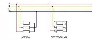
(Current values for delta and star connections at minimum voltages)
(Current values for delta and star connections at maximum voltages)
Now, using the first formula, you can calculate the full load current:
I for "triangle":
I for "star":
The values for full load current correspond to the permissible motor full load current at 254 Δ/440 Y V, 60 Hz.
Attention : The external motor overload relay is always set to the rated current value indicated on the nameplate.
However, if motors are designed to have a load factor, which is then indicated on the nameplate, e.g. 1.15, the current setting for the overload relay can be increased by 15% compared to full load current or service factor amps (SFA). ), which is usually indicated on the nameplate.
Operating principle and functions of phase control relays
So, in each machine there is a correct phase order in which all motors for a given connection rotate in the correct direction. If the supply phases are mixed up, then everything will also spin, but incorrectly, and perhaps not for long.
The phase control relay has a circuit that calculates the phase sequence (Phase-sequence), and the output contacts operate in accordance with this order. These contacts can be connected anywhere - into the control circuit
, to a bell or light bulb, break the power circuit, the power supply circuit of the entire device or the motor contactor coil.
The last use is recommended by the manufacturer, but I recommend including it in the emergency (control) circuit so that the entire machine in which this relay is installed cannot start. Naturally, if the emergency circuit is executed correctly, as I recommend in the article at the link provided.
This is the main application.
Another application is protection against phase loss (Phase-loss). Or from a significant decrease in voltage on one of the phases ( asymmetry, or phase imbalance ) (Three-phase Asymmetry).
The last two functions are basically identical, the only question is the level of voltage drop.
An automatic motor or thermal relay is also used to protect electric motors from phase failure, but they are triggered by thermal overload, and this is already a critical mode. And the phase control relay is an electronic device, and will work earlier (1-3 seconds), preventing the engine from overheating. In the case of phase alignment, switching on does not occur immediately, but after the required time (5-10 seconds).
The asymmetry voltage level can be set in all phase control relays, but the on/off time, as a rule, is regulated only in sophisticated models. In addition, the asymmetry detection function has a useful parameter called hysteresis, which ensures smoother operation of the device. It is also usually not regulated.
How hysteresis works, ask someone who knows what it is))
Thus, we can say that a phase control relay is a device that monitors the quality of three-phase supply voltage in industrial equipment. And naturally, the phase control relay is a 3-phase device.
Types of intermediate relays
Intermediate relay for Din rail
By design, they are divided into relays, electromagnetic intermediate or mechanical and electronic devices. Mechanical relays can operate under different conditions. These are durable and reliable devices, but not accurate enough. Therefore, more often their analogs are mounted in the circuit - electronic relays on a DIN rail. The relay can also be installed on a flat surface. To do this, the lock latches need to be moved apart.
Based on their purpose, devices are divided into the following categories.
- Combined interdependent devices operating in a group.
- Logic devices that operate on microprocessors in a circuit with digital relays.
- Measuring, with an adjustment mechanism, triggered at a certain signal level.
According to the method of operation of the RP, there are direct ones, which directly open or close the circuit, and indirect ones, which work together with other devices. They do not open the circuit immediately after a signal is received.
There are devices of the maximum switching type, when operation occurs at the moment the threshold value of the circuit parameter increases. The minimum type is triggered during a decrease in characteristics.
According to the method of connection to the circuit, there are primary ones that can be connected directly to the circuit. Secondary ones are installed through inductors or capacitors.
Three-phase voltage control relay EL-11, EL-12 and EL-13
Hello, dear visitors and readers of the Electrician's Notes website.
This article will focus on phase control relays of the EL-11, EL-12, EL-13 types, as well as its modernized models EL-11MT and EL-12MT.
These relays are also called three-phase voltage control relays.
I came across these relays for the first time recently, because they are not widely used in relay protection and automation circuits. For these purposes, we use simpler and no less reliable electromechanical relays.
And then the other day a colleague from the “shop” asked to check the EL-11 phase control relay, which was installed in his ATS (automatic transfer switch) circuit at the input of the administrative building. According to him, the phase control relay did not work correctly, and most likely did not work at all.
Operating principle of thermal circuit breaker
The graph on the right shows resistance versus temperature for a standard thermal circuit breaker. Each manufacturer has its own characteristics. TN usually lies in the range of 150-160 °C.
Connection
Connection of a three-phase electric motor with built-in thermal switch and overload relay.
TP symbol on the chart
Protection according to IEC 60034-11:
TP 111 (gradual overload). In order to provide protection when the rotor is blocked, the electric motor must be equipped with an overload relay.
Thermistors built into windings
The second type of internal protection is thermistors, or positive temperature coefficient (PTC) sensors. Thermistors are built into the windings of the electric motor and protect it when the rotor is blocked, prolonged overload and high ambient temperatures. Thermal protection is provided by monitoring the temperature of the motor windings using PTC sensors. If the winding temperature exceeds the shutdown temperature, the sensor resistance changes according to the temperature change.
As a result of this change, the internal relays de-energize the control circuit of the external contactor. The electric motor cools down, and the acceptable temperature of the electric motor winding is restored, and the sensor resistance drops to its original level. At this moment, the control module is automatically reset to its original position, unless it has previously been configured to reset the data and turn it on again manually.
If the thermistors are installed at the ends of the coil themselves, the protection can only be classified as TP 111. The reason is that the thermistors do not have full contact with the ends of the coil, and therefore cannot respond as quickly as if they were originally built into the winding.
The thermistor temperature sensing system consists of positive temperature coefficient (PTC) sensors installed in series and a solid state electronic switch in an enclosed control box. The set of sensors consists of three - one per phase. The resistance in the sensor remains relatively low and constant over a wide temperature range, with a sharp increase at the response temperature. In such cases, the sensor acts as a solid state thermal circuit breaker and de-energizes the monitoring relay. The relay opens the control circuit of the entire mechanism to turn off the protected equipment. When the winding temperature is restored to an acceptable value, the control unit can be returned to its previous position manually.
All Grundfos electric motors with power from 3 kW and above are equipped with thermistors. A positive temperature coefficient (PTC) thermistor system is considered to be fault tolerant because when a sensor fails or a sensor wire is disconnected, infinite resistance occurs and the system responds in the same way as when the temperature rises - de-energizing the control relay.
IPC / Tags
Device for protecting three-phase voltage consumers from phase loss and phase rotation changes
Patent number: 957344
. 15 and 16, respectively. The doors of the other arms of the phase-sensitive star contain a transistor 17 connected to the first phase by the emitter, a base through a resistor 18 to the input terminal 4, and a parallel circuit of capacitor 19 and resistor 20 is connected in series with it, and a transistor 21 connected by the emitter to the input terminal third phase, in the base - to the output terminal 6 through resistor 22, resistor 23 is included in the collector of this transistor. The emitter-base junctions of the 4 transistors are shunted: by diodes 24, 25 and 26. The device operates as follows. If we assume that the supply voltage of phases 1, 2 and 3 is connected to input terminals 1, 2 and 3, respectively, and the load is connected to output terminals 3, 4 and 5, then through the bases.
Current protection against multiphase short circuits in the motor stator winding
Protection against multiphase faults in the stator winding should operate as quickly as possible. For this purpose, overcurrent protection with dependent or independent time delay is used. In this case, for quick shutdown in case of short circuit overcurrents, a current cutoff is used, which is adjusted from the maximum value of the starting current at the moment the engine is turned on. The remaining range of possible short-circuit currents is covered by overcurrent protection stages with an independent (dependent) time delay.
The function of dynamic switching of protection parameters (setpoints) ensures its hardening for a certain time (when the electric motor is turned on after a previous pause) and thereby increases sensitivity to short circuits. In this case, a signal of the presence of a previous pause in the voltage supply is generated, and the overcurrent protection settings are switched, which ensures that the protection is blocked during the subsequent start of the engine.
Danger and consequences of misalignment
What is the danger of phase imbalance in the electrical network? Conditionally negative aspects can be divided into three groups:
- Harm to electrical receivers (devices, equipment): damage to them, reduction in service life.
- Harm to electricity sources: mechanical damage, increased electricity consumption, reduced service life of the source.
- Consequences for consumers: increased electricity costs, need for electrical equipment repairs, possible injury.
Due to the fact that electricity is distributed unevenly across conductors, electricity consumption in the electrical network increases significantly. A three-phase network that has developed asymmetry can reduce the service life of electrical appliances and household appliances.
If this is an autonomous power plant, then the oil and fuel consumption in this situation increases significantly, and the generator may break down. When one phase receives more voltage than the other two, electrical safety is compromised. And this can lead to various electrical injuries, as well as fire of electrical household appliances and the wiring itself.
As you can see, the consequences of this phenomenon are significant and their solution and elimination can lead to large material costs. In order to avoid such an unpleasant situation, certain measures should be taken in advance.
How it works
In order to understand the importance of installing a voltage control relay in your home, you need to understand the principle of its operation. This is special equipment that responds to changes in voltage in the electrical network of the room. The usual circuit for installing a protective device is the connection between the energy supply meter and the distribution panel
Its work is aimed at fixing a certain voltage level on the power supply line. If the value is outside the default or arbitrary range, the voltage control relay will disconnect the circuit to ensure the safety of all electronics and other equipment that were connected to the electrical network.
The most important element in the design of this protective equipment is the voltage relay. It is manufactured on the basis of a microprocessor or a standard comparator. In designs with a built-in microprocessor relay, voltages usually have increased smoothness when regulating the minimum and maximum voltage levels in the electrical network.
The ability to independently set the permissible operating range of the installation makes it more versatile than designs with a static value. This may be due to the operating requirements of a certain type of equipment. The ability to adjust the operating range of the voltage control relay is not provided in all designs for this purpose. If the device provides the ability to change the sensitivity threshold, then the function is implemented using a toggle switch on a graduated scale.
Also, a very important characteristic of a safety device is its response speed when there is a sudden change in voltage in the electrical network. In order to provide electrical equipment with the best protection, the voltage control relay must operate in a minimum time
The safety of all devices connected to the line usually depends on this. If the time period is too long, connected household appliances and electronics may burn out, causing significant losses for the family.
Therefore, you should not save on installing such a device. Today there are devices that can de-energize an entire line in tens of nanoseconds, which is a very good indicator. This protective equipment has nothing in common with a conventional stabilizer, which is aimed at constantly equalizing the voltage in the network to a stable one in order to ensure normal functioning of all connected devices. During sudden voltage surges, the stabilizer will not protect electrical equipment.
PROTECTIVE DEVICES FOR MOTORS ABOVE 1000 VOLT
The security of high-voltage electrical machines is ensured only by remote relay devices. Thermal and electromagnetic releases are the prerogative of low-voltage devices.
The principle of operation and calculation of the settings for current cut-off and overload protection are the same as for low-voltage machines. But besides this, there are specific protective devices that are not used at low voltages.
Protection against single-phase earth faults.
A feature of high voltage networks (6 – 10 kV) is operation in isolated neutral mode. In such networks, the magnitude of a ground fault can be only a few amperes, which is outside the sensitivity zone of maximum current overload protection.
Single-phase earth faults are characterized by the presence of zero-sequence currents flowing in the same direction in all three phases.
The ground protection relay for the electric motor (this is its name in the jargon of relay specialists) is connected to a special zero-sequence transformer, which is a torus (donut) through which the power cable passes.
In this case, the output of the shielding shell of the high-voltage cable should not pass through the torus, otherwise false operations of the device will occur and the switch will trip.
2012-2020 All rights reserved.
The materials presented on the site are for informational purposes only and cannot be used as guidelines or regulatory documents.