Three-phase electric motors can be connected in different ways. Each of the schemes has its own technological nuances, advantages and disadvantages. Features of star and delta motor connections.
Asynchronous machines are a class of technological equipment that has a wide range of advantages. The positive aspects of such an engine include increased performance, which allows for a more complex list of technical processes, and reliability. Also settings:
- unpretentious in operation;
- repairing an electric motor is not difficult - this ensures significant savings when carrying out restoration measures;
- an asynchronous three-phase unit tolerates high overloads of the mechanical type.
The above-mentioned positive aspects are due to the simple design. The same applies to the possibility of using star or delta connection methods. Ensuring uninterrupted operation of an asynchronous motor involves the use of various types of connections, which include star and delta.
Depending on the specifics of the technical process, the windings of a three-phase motor, generators, and transformers are connected using different methods, i.e. The connection of the windings varies. The variety of ways to connect a three-phase motor affects the technical characteristics of the installations. Therefore, the method is selected taking into account the technological features of the operations for which the unit will be used.
Why do we need diagrams?
The start-up is notable for the occurrence of a starting load that significantly exceeds the rated parameter. If the engine is low-power, then special protective components can withstand the impact. But in the case of high-power units, an inevitable voltage drop occurs. Fuses and circuit breakers designed to protect industrial installations from destructive influences fail. The rotation frequency of the moving part during startup is significantly lower than the rated speed.
The inrush current is reduced in the following ways:
- placement in the system with a transformer, inductor or control rheostat;
- switching the connection diagram of the rotor windings - occurs using a production automation system (PAS). Responsible for automated adjustment of the functionality of the enterprise infrastructure - turns on certain equipment, turns off technological equipment if it is not needed at the moment.
The latter method is more widely used in production - it is quite simple and effective. A reduction in inrush current is achieved by changing the star-to-delta circuit. When starting the engine, the windings are connected in a star, and after gradual and uniform acceleration, they are switched to a triangle.
Recommendation : If the equipment uses both circuits, then an additional neutral from the power supply network is connected to the common connection point. During operation, amplitude phase asymmetry is possible. Neutral compensates for this effect, which prevents problems with the performance of power units.
These electric motor circuits differ significantly from each other. Before connecting a three-phase motor using the delta or star method, it is necessary to understand as accurately as possible the nuances of each of the circuits. Otherwise, instead of a positive result in the form of efficient operation, there is a possibility that serious problems will arise with the functioning of the equipment.
Theory
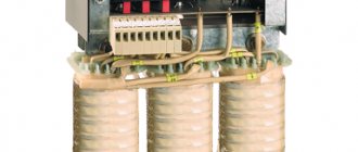
As already mentioned, star and delta connection diagrams are typical not only for an electric motor, but also for transformer windings, heating elements (for example, electric boiler heating elements) and other loads.
To understand why these connection diagrams for the elements of a three-phase circuit are called that way, you need to modify them somewhat.
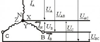
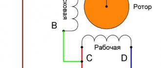
In a “star”, the load of each phase is connected to each other by one of the terminals, this is called the neutral point. In a “triangle”, each of the load terminals is connected to opposite phases.
Everything said in the article below is true for three-phase asynchronous and synchronous machines.
Let's consider this issue using the example of connecting the windings of a three-phase transformer or a three-phase motor (in this context it does not matter).
In this figure, the differences are more noticeable; in a “star,” the beginnings of the windings are connected to the phase conductors, and the ends are connected together; in most cases, the neutral wire from the supply generator or transformer is connected to the same load point.
The dots indicate the beginning of the windings.
That is, in a “triangle” the end of the previous winding and the beginning of the next are connected, and the supply phase is connected to this point. If you confuse the end and the beginning, the connected machine will not work.
Three-phase motor technology diagrams: star and delta connection, more about methods
If we recall the principle of operation of asynchronous equipment, then the power of such equipment comes from a three-phase voltage (alternating) network. The stator (also known as the stationary component) has three windings. The latter are shifted relative to each other - a shift of 120 degrees.
This approach is an unproductive error; it was done deliberately so that a rotating magnetic flux (MF) is formed. Stator windings have special designations:
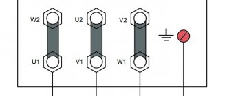
- the beginning of the windings – C1-C3;
- end of stator windings – C4-C
The above markings are outdated, but are still used. The new designation is as follows:
- beginning – U1, V1, W1;
- end – U2, V2, W2.
The conclusions are output directly to the terminal block, block. They are positioned in such a way that a star or delta connection can be made without crossing jumpers on a three-phase motor. The terminal block (aka boron) is located at the top, less often - on the side of the unit. Some of these parts can be easily unfolded to facilitate installation and connection. This also simplifies the installation of cables for power supply systems.
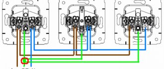
A star connection involves connecting the windings at one point. The latter is called zero, neutral, and is designated “O”. Produced through the use of a jumper, a three-phase electrical load is supplied to the beginning of the windings. Provides for the connection of all three windings. This connection with a 380V/220 network has some nuance. An electrical load of 220V is supplied to each winding, and 380V to those connected in series.
The triangle connection is carried out as follows: the beginning of the first phase is combined with the end of the second, and the beginning of the second with the end of the third, and the beginning of the third with the end of the first. Three-phase voltage is supplied to the places where the windings are connected.
Important : Special circuits are needed due to the fact that the electric motor, if power is supplied directly, experiences increased starting currents and increased loads. This leads to premature wear of the internal components of the installation, increasing the likelihood of serious breakdown, followed by costly repairs to electrical equipment.
The use of diagrams is especially important in systems where there is no reduction gear, for example, a gearbox or belt is not installed on the pulleys. They are also used when dimensional elements are located on the shaft - impellers, centrifuges. They are used to ensure trouble-free operation of high-power units - extremely important for electric motors producing power over 5 kW with a rotation speed of more than 3 thousand revolutions/minute.
In order to reduce power at start-up, a special technology is used. The equipment is turned on at a reduced voltage, followed by uniform acceleration. Further, the equipment is operated at rated power. This principle of operation is implemented not by regulating the voltage by other components such as a rheostat or transformer, but more deeply and effectively by connection diagrams.
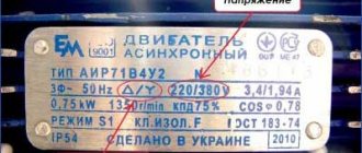
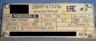
Tip : The motor connection type is indicated on the back cover of the boron. Production information will allow you to immediately study the basic technical characteristics.
The power of the motor shaft is equal in both star and delta, but subject to the supply of rated voltage. The currents are different - the differences are due to varying characteristics - the parameters are different. The star is notable for its line voltage greater than the coil rating, and the delta has a current higher than the coil.
With a base coil voltage of 220V, the indicator in the “Star” circuit is 380V. Some of the mentioned parameters (or all at once) are indicated by the manufacturer of the power plant on the nameplate. Knowing one of the voltages, you can easily calculate the other performance characteristics. Therefore, you should carefully study all the passport information presented along with the electrical equipment.
What is a delta winding connection?
Connecting windings in a triangle consists of connecting the end of each winding to the beginning of the next. The end of the first winding is connected to the beginning of the second. The end of the second is from the beginning of the third. The end of the third winding creates an electrical loop because it completes the electrical circuit.
With this connection, a linear voltage is adjusted to each winding, usually equal to 220 or 380 V. Such a connection is physically implemented using metal jumpers, which must be provided with the factory equipment of the electrical equipment.
What types of electric motors can be connected according to the diagrams?
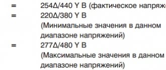
Modern industry produces a wide range of electric motors designed to solve technical problems of any complexity. They differ in characteristics, functionality, and design. One of the most popular installations are low-voltage units. Used in 0.4 kV 50 Hz networks. They differ in two voltages - 220/380, 380/660V.
Interesting : The first number indicates the characteristic for a star connection, and the second for a triangle connection. But there are ratings that operate at non-standard voltages - 230/400, 240/400V.
Connection of 220/380V units
Equipment operating at low voltage has special connection specifications. Such equipment can be used at 220V using a phase-shifting capacitor or a single-phase frequency converter in the circuit. In this case, the network should be exclusively single-phase, and the principle should be only a triangle. 380V units are connected to a three-phase power supply via a contactor, soft starter or via a frequency converter in star only.
What is an industrial contactor?
An industrial contactor (IC) is a specialized two-position device, which is an apparatus operating on an electromagnetic principle. It is designed for frequent remote switching on/off of industrial electrical circuits. This device is one of the types of electromagnetic relays.
The most commonly used are one- and two-pole contactors operating with direct current, and three-pole contactors operating on alternating current. Due to the fact that a significant number of switchings occur, particularly stringent requirements are imposed on the elements regarding certain characteristics. The latter includes resistance to mechanical and electrical wear.
Design of industrial contactors used in the “Triangle” circuit for connecting 380V electric motors:
- electromagnetic system;
- contact complex, including moving/static contacts;
- arc suppression system;
- block contacts - the latter switch the signaling circuit and control system during operation of the contactors.
Industrial contactors are capable of switching only nominal characteristics, and therefore it is not advisable to use them to influence short-circuit currents. The PC control process occurs due to the influence of the auxiliary circuit. The components show themselves most effectively in electrical circuits with voltages up to 660V and up to 1.6 thousand A. The specific operation involves use for controlling high-power electric motors, switching reactive power compensation circuits and high direct currents.
Motors 380/660V
Such installations are the best option for a Star/Delta connection. When working directly through a contactor and a frequency converter, the windings are assembled into a “triangle”. As practice shows, 660V is not used or is used in highly specialized tasks. Therefore, most often circuits are used to accelerate the moving part of an electric motor.
Frequency converter (FC)
An element is an electronic device designed to vary the frequency of an electric current. It is necessary to convert the mains 3-phase or single-phase alternating current of 50 Hz into a similar one, but with a higher frequency. Electrical induction frequency generators are produced. The design is similar to an asynchronous electric motor equipped with a wound rotor, which is capable of operating as a generator or electronic converter.
Frequency generators of asynchronous type are used in the arrangement of a system for smoothly controlling the speed of an asynchronous machine or a synchronous motor. This occurs by generating an output voltage of a certain frequency. Simple control specifications are based on changes in voltage-frequency characteristics, and more complex ones involve vector control.
Element base of the frequency generator:
- rectifier bridge responsible for converting alternating current into direct current;
- inverter – converts direct current into alternating current corresponding to the required frequency;
- GTO thyristors, transistors
The shape of the output voltage is improved by the location in the space between the motor and the inductor converter. Electromagnetic interference is reduced by an EMC filter.
How to reduce starting currents of an electric motor?
The phenomenon of a significant increase in inrush currents when starting high-power devices connected according to the Δ circuit leads in networks with overload to a short-term voltage drop below the permissible value. All this is explained by the special design of the asynchronous electric motor, in which the rotor with a large mass has high inertia. Therefore, at the initial stage of operation, the motor is overloaded, this is especially true for the rotors of centrifugal pumps, turbine compressors, fans, and machine tools.
To reduce the influence of all these electrical processes, they use a “star” and “delta” connection to the electric motor. When the engine picks up speed, the knives of a special switch (a starter with several three-phase contactors) transfers the stator windings from the Y circuit to the Δ circuit.
To implement mode changes, in addition to the starter, you need a special time relay, thanks to which there is a time delay of 50-100 ms when switching and protection against three-phase short circuits.
The very procedure of using the combined Y/Δ circuit effectively helps to reduce the inrush currents of powerful three-phase units. This happens as follows:
When a voltage of 660 V is applied according to the “triangle” circuit, each stator winding receives 380 V (√3 times less), and, therefore, according to Ohm’s law, the current strength decreases by 3 times. Therefore, when starting, the power in turn decreases by 3 times.
Operation of the Star/Delta connection circuit
The operating principle is based on four stages:
- the terminals that have the appropriate markings (discussed above), U1, V1, W1, are supplied with power with the same voltage in all modes. The remaining terminals U2, V2, W2 are combined at one point - a “Star” is organized, replacing the 660-volt rating with 380V. The actual parameter is 220V;
- The electric motor operates from 5 seconds - the time may vary. It depends on how heavy the launch was. The operating period is set by another automation component - a time relay. It is also connected within the circuit;
- the power supply is removed by means of a second timer, and the unit itself, according to the principle of inertia, carries out a couple of rotation periods, according to the voltage. Typically, this is from 50 to 500 ms. This protective gap is necessary to avoid interruptions in performance. It guarantees the normal functioning of the circuit. The industrial “star” contactor must have time to turn off before the “delta” contactor comes into operation. The nuance must be taken into account due to the more delayed switching off of contactors - the effect is due to the magnetization process;
- further, the “star” mode changes to “triangle”. In it, the motor operates at nominal characteristics until the end of the technical process.
Instead of a second timer, a complex can be used that blocks mode switching until the “star” is turned off. It is impossible to do without additional regulators - correct operation will not be ensured if the time interval is disrupted.
Arrangement of the power section (MF)
The electrical unit is switched on using industrial contactors in the amount of three units. The common PC starts the electrical load on the terminals U1, V1, W1, the star contactor - combines U2, V2, W3 into a single point - needed to accelerate the rotor.
The last PC is a “triangle” element that supplies the necessary electrical load to the terminals U2, V2, W2, which allows the installation to function normally. There are projects where soft starters (SCDs) are used instead of contactors.
MF based on SCP
Soft starters are various classes of devices whose task is to ensure smooth starting and stopping of electric motors. Devices are used:
- for smooth acceleration of the motor and its smooth stop;
- reducing the current that occurs at the moment of starting the power plant;
- equalizing torque and load torque.
Starting is characterized by a multiple increase in torque - 200% more than the nominal one. The effect causes destruction of the mechanical structure of the electric drive. The operation of the soft starter limits the rate of increase of the inrush current at a certain moment.
Thyristor switches (also known as soft starters), made on the basis of controlled valves, provide a simple way to regulate the rate of increase/decrease of voltage, which creates the required basic conditions for the safe operation of electric motors. Soft starters allow you to form phase regulation and change voltage characteristics.
Installation of soft starters provides the ability to control electromagnetic torques (the dynamics of a three-phase asynchronous electric drive). Taking into account the specifics of the load, soft starters can equip various modes for monitoring the performance of the electric motor.
Control modes:
- linear dependence - is formed by installing frequency converters of simple design. This is necessary to create a stable load torque while simultaneously monitoring the operation of asynchronous units, parallel-connected motors;
- quadratic dependence – relevant in the operation of drives of pumping units and fans;
- vector and flux linkage control - both methods are based on the operation of the adaptive design of the motor model.
The last control mode is a method in which the operation of both synchronous and asynchronous machines is monitored. According to vector control (VC), harmonic phase currents are formed and control of the magnetic flux of the moving part of the installation is ensured. The control unit is organized by several technologies, including the use of a mathematical model without additional measurements, with the latter using electric motor speed sensors.
Creating a control part
Industrial devices are launched using several methods - the most suitable one is selected taking into account the specifics of the process. The following methods of use exist:
- using three toggle switches - the main thing is to follow the on/off algorithm. Quite simple and cheap way of control;
- using a specialized switch - sold in certified hardware stores or assembled by hand. To assemble it yourself, you need a biscuit/cam PKP;
- application diagram with a preset timer relay;
- control using a specialized element;
- universal control through a controller - the technique is relevant if the enterprise has an industrial automation system.
Some low-current systems are equipped with galvanic isolation from the power system by installing a transformer or power supply. The only caveat is that the voltages of the starter coils must be matched. Voltage is supplied to the circuit using both toggle switches and a classic self-retaining circuit.
More details about the circuit with a time relay
The element refers to the components that create infrastructure automation. Devices are necessary to form an independent time delay necessary to ensure a given sequence of operation of the components. The devices are used when a certain operation needs to be carried out not immediately, but after a certain period of time.
There are relays such as;
- electromagnetic;
Relevant exclusively for machines operating on direct current. There is an auxiliary short-circuited winding made of a copper sleeve. When the main magnetic flux increases, a current is created in the additional winding. The result is that the rate of increase in magnetic flux is less, the time of armature shift decreases - a shutter speed is formed. Range from 0.07 to 0.11 s when turned on, and 0.5 - 1.4 when turned off.
- pneumatic;
The relay is distinguished by the presence of a damper, which acts as a slowing component. The adjustment is carried out by monitoring the cross-section of the hole responsible for air intake. Range – from 0.4 – 180 seconds.
- anchor and sentry;
Operates via a spring. It is started by an electromagnet, the contacts come into operation after counting the period of time set on the device scale. Often used in high-power circuit breakers. The design is represented by a slowing mechanism, a current winding. Spring tension affects the travel speed parameter. At the end of the stroke, the product turns off the machine, which provides protection against the temperature effects of overload. Range – 0.1 – 20 seconds.
- motor elements;
They are used to count time intervals from 10 seconds to several hours. Design: gearbox, small synchronous motor, electric magnet. The latter engages and disengages the contact pairs of the motor and gearbox.
- electronic;
Operation is adjusted using analog (integrated) elements and digital devices. Specialized relays are manufactured on the basis of a microprocessor element base.
It is worth noting that modern equipment practically does not use the “Star/Triangle” principle based on a time relay due to some disadvantages:
- capriciousness of pneumatic, mechanical devices;
- installation of a second relay that performs the task of maintaining a pause between modes;
- almost identical cost of operating a standard and specialized relay.
The acceleration time is selected smoothly - from 1 second to 16 minutes, the pause varies in steps, based on the acceleration time of the work. The control panel is presented:
- power indicators – green if power is connected;
- indicators indicating mode switching - flashes red when “Star”, lights without flickering if “Triangle”;
- a regulator, also known as a switch, with the ability to select a time range - together with a multiplier potentiometer, it provides the setting of any time;
- a regulator that allows you to smoothly set the time period.
The configuration of the connection diagram for a three-phase asynchronous motor depends on the nuances of production operations, the technical characteristics of the power unit itself, and the capabilities of the infrastructure.
How to control motor switching
Often, to start a high-power electric motor, switching the delta connection to a star connection is used; this is necessary to reduce the current parameters at start-up. In other words, the engine starts in star mode, and all work is carried out on a delta connection. For this purpose, a three-phase contactor is used.
When automatically switching, the following prerequisites must be met:
- block contacts from simultaneous activation;
- mandatory performance of work, with a time delay.
A time delay is necessary for 100% disconnection of the star connection, otherwise, when the delta connection is turned on, a short circuit will occur between the phases. A time relay (RT) is used, which delays the switching by an interval of 50 to 100 milliseconds.
Functioning of "Star"
State standard GOST 28173 (analogous to IEC 60034-1) states that it is permissible to use power plants when the electrical load deviates by 5, both upward and downward, with a similar frequency deviation of 2%. The technical parameters of the units may vary from the nominal ones. In this case, the temperature conditions of the windings may exceed the permissible values according to the mentioned GOST by 10 degrees.
Starting the engine outside the mode significantly increases the temperature effect on the internal structure of the power unit. This leads to overheating, which negatively affects the condition. Therefore, it is extremely important to ensure timely cooling and protection from such influence of the specific operation.
Differences
The difference between both connection principles is that even if the same network is used, the electrical load parameters may differ. Also, connection methods differ in implementation technology.
“Triangle” is used less frequently due to the increased load on the motor. The star-shaped connection principle has a gentle effect on the electric drive and transformer. The current passing directly through the windings is less. The “triangle” is used in the construction of high-power mechanisms and industrial units, where a significant starting load is required. Significant current parameters contribute to high EMF values. The latter - greater torque.
Important : For significant starting loads, you should not use star technology. Using this principle, you can cause significant damage to the engine. The effect is due to the lower torque.
Advantages of the star method:
- power reduction, which increases the reliability of electrical equipment;
- stable use without jumps in technological parameters;
- formation of a smooth start without a sharp increase in characteristics.
There is equipment that is designed to use exactly the above method. The equipment has an internal connection of windings. 3 outputs are connected to the terminal block.
Advantages of using a “triangle”:
- possibility of using higher power units;
- insignificant inrush currents;
- increased torque;
- strengthening traction characteristics.
Acceptable connection methods are indicated on the motor nameplate. There are installations that can operate in several modes, and units that do not provide for operation in two connection technologies at once. Information about the characteristics is provided directly by the manufacturer. But it is worth understanding that any changes to the internal design may affect the installation parameters. This must be taken into account when a “makeshift” engine upgrade is carried out.
Advantages and disadvantages of the “triangle”
Using this type of connection allows you to create an unbroken circuit in the electrical circuit. The circuit received this name because of its ergonomic shape, although it can also be called a circle. Among the advantages of the “triangle” it is worth noting:
- The maximum power of the unit is achieved during operation.
- A rheostat is used to start the motor.
- Significantly increases torque.
- A powerful traction force is created.
Among the disadvantages, one can note only high values of starting currents, as well as active heat generation during operation. This type of connection is widely used in powerful mechanisms that contain large load currents. It is due to this that the EMF increases, affecting the power of the torque. It should also be said that there is another connection diagram called “open delta”. It is used in rectifier installations designed to produce triple-frequency currents.
Reverse
Industrial complexes allow switching between modes (if provided by the equipment manufacturer). The reverse principle is based on the installation of a relay contactor element base (RCEB) - the engine reaches certain values, the switching module is activated, and the connection changes.
The presence of RCEB increases the reliability and productivity of the power machine since the equipment will not be used constantly at maximum performance. The need for the latter is determined by an automatic infrastructure management system.
What does the PUE say?
Electric motors used to ensure the operation of power machines and performing a single technical process must be equipped with a common switching device - if safety requires this. Otherwise, it is allowed to equip the engines with separate switching devices (CDs).
CPs located in common circuits with motors must simultaneously turn off all conductors through which voltage passes. If the enterprise infrastructure contains remote, automatic control of an electric motor (AEC), then a specialized emergency shutdown device is located near the latter. This forms protection against emergency incidents occurring due to interruptions in the operation of units.
The PUE allows for the absence of an AUE if:
- installations exclude the possibility of any accidental contact with the rotating elements of the mechanisms. Posters are placed near such installations notifying that the unit can be started using remote control or automatically;
- power plants are equipped with specialized devices that provide local control with a subsequent shutdown command.
The need to install automatic shutdown devices is determined at the design stage of industrial manipulator complexes. In this case, AUE circuits can be powered both from a centralized power supply and through decentralized sources of electricity.
Prevention of sudden starts is ensured by interlocking communication. It automatically turns off the main circuit when there is no power. Devices responsible for switching must have increased resistance to rated short-circuit currents.