How to connect a three-phase motor to a 220 or 380 V network?
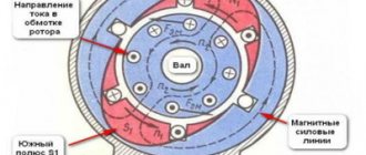
Among electrical machines designed to perform mechanical work, three-phase units are considered one of the most productive. The rotor rotates through the simultaneous influence of magnetic flux from the phase windings. Which ensures the simultaneous force of three moments at once, proportionally interacting with each other. How you can connect a three-phase motor, depending on their design features and the parameters of the electrical network, we will consider further.
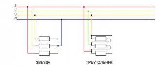
Connection diagrams STAR and DELTA
Manufacturers offer three-phase electric motors both with the ability to change the connection diagram and without it.
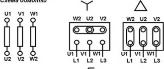
The earlier designation of the winding terminals C1 - C6 corresponds to the modern U1 - U2, W1 - W2 and V1 - V2. In distribution The box contains three wires (the factory default connection diagram is *star*) or six (the motor can be connected to a three-phase network with either a star or a delta). In the first case, it is necessary to connect the beginning of the windings (W2, U2, V2) at a single point, and connect the three remaining wires (W1, U1, V1) to the phases of the supply network (L1, L2, L3).
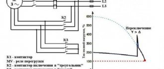
The advantage of the star method is smooth motor starting and soft operation (due to gentle operation and a beneficial effect on the operating life of the unit), as well as lower starting current. The disadvantage is a loss of power by about one and a half times and less torque. It is used for equipment that has a freely rotating load on the shaft - fans, centrifugal pumps, shafts of machine tools, centrifuges and other equipment that does not require torque. The triangle diagram is used for electric motors that initially have a non-inertial load on the shaft, such as the weight of a winch load or the resistance of a piston compressor. To reduce the starting current, a combined type of switching
(applicable for electric motors with a power of 5 kW or more) - combining the advantages of the first two schemes - the start-up occurs according to the star circuit, and after the electric motor enters the operating state, automatic (time relay) or manual switching (packet) occurs - the power increases to the nominal.
Uniting at one common point: star connection
The ends of the stator windings are connected together at one point. Three-phase voltage is supplied to the beginning of the windings. The value of inrush currents when connecting a triangle is more powerful. A star connection means a connection between the ends of the stator winding. Voltage is supplied to the beginning of each winding.
Connection drawing of a classic frequency converter with a star
According to this scheme, domestic 380 volt motors are connected.
Expert opinion
It-Technology, Electrical power and electronics specialist
Ask questions to the “Specialist for modernization of energy generation systems”
MONTAĜKA: Star and triangle. Connecting motors. Such two-phase networks should not be confused with the two-phase networks that existed at the beginning of the 20th century in the USA, where the phases were shifted by 90 degrees, to which motors with two windings, like modern servomotors, could be directly connected. Ask, I'm in touch!
Using a frequency converter
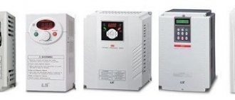
Currently, everyone has quite actively begun to use frequency converters to control the rotational speed (RPM) of an electric motor.
This allows you not only to save energy (for example, when using frequency control of pumps for water supply), but also to control the supply of positive displacement pumps, turning them into dosing ones (any pumps of a positive displacement principle).
But very often when using frequency converters, they do not pay attention to some of the nuances of their use:
- frequency adjustment, without modifying the electric motor, is possible within the frequency adjustment range +/- 30% of the operating frequency (50 Hz), - when the rotation speed increases above 65 Hz, it is necessary to replace the bearings with reinforced ones (now, using a state of emergency, it is possible to increase the current frequency to 400 Hz , ordinary bearings simply fall apart at such speeds), - when the rotation speed decreases, the built-in fan of the electric motor begins to work inefficiently, which leads to overheating of the windings.
Due to the fact that they do not pay attention to such “little things” when designing installations, very often electric motors fail.
To operate at low frequencies, it is MANDATORY to install an additional forced cooling fan for the electric motor.
A forced cooling fan is installed instead of the fan cover (see photo). In this case, even with a decrease in the shaft speed of the main engine, an additional fan will ensure reliable cooling of the electric motor.
We have extensive experience in retrofitting electric motors to operate at low frequencies. In the photo you can see screw pumps with additional fans on electric motors.
These pumps are used as dosing pumps in food production.
We hope that this article will help you correctly connect the electric motor to the network yourself (or at least understand that this is not an electrician, but a “general specialist”).
How do you know whether to connect with Star or Triangle?
Three-phase AIR motors have two rated voltages: 220/380 V and 380/660 V, which is indicated on the nameplate. This is the main criterion for choosing the type of connection of asynchronous motors.
| Electric motor connection diagram | Voltage | |
| Star | 380 V | 660 V |
| Triangle | 220 V | 380 V |
- Electric motors 220/380 - modern models up to size 112 - 7.5 kW. Previously, they were produced in sizes up to 315 - up to 132 kW. Connection to a 220V network with a triangle, to 380V with a star.
- Electric motors 380/660 - found in models with a power of 4 kW or more. The circuit for 380V is triangle, for 660V it is star.
Star
The “star” provides that the ends of the stator windings are closed at one point, called the zero point or neutral, and the beginnings are connected to their phases - L. Therefore, it is customary to start medium-power motors with a “star”. However, it is impossible to achieve the rated power of the electric motor.
Advantages of the “Star” connection scheme:
- Smooth start
- More reliable engine operation
- Not long-term overload is allowed
Triangle
When connecting a motor in a triangle, the end of one stator winding is connected in series to the beginning of the next. However, delta connection significantly increases inrush currents, which can lead to insulation breakdown; the engine heats up more.
Advantages of the “Triangle” connection diagram:
- Operating power corresponds to the nameplate
- Increased torque
- Improved traction
"Star-delta" (combined)
In the case of powerful electric motors (starting from 5.5/3000), it is important to ensure a smooth start without overloads and further operation at maximum power. Such motors are often connected in a star-delta configuration. It is only suitable for models marked (Δ/Y), which indicates the possibility of connection in two ways.
The combined connection diagram will protect the motor from high starting currents and ensure the nominal power of the motor. Practically it looks like this: the electric motor starts in a star pattern, and when it gains speed, it switches to a triangle pattern, either automatically or with the help of additional devices. In this case, current surges are possible.
Star/delta starting is suitable for motors with large flywheel masses that are immediately loaded at rated speed.
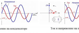
Connecting the motor to a single-phase 220V network via a capacitor
To use an asynchronous electric motor from a 220V household electrical network, a phase-shifting capacitor is used. This ensures a soft start of the unit. Methods for connecting capacitors to a 220V household network:
- with switch
- directly, without switch
- parallel connection of two electrolytes
The capacitor for the motor must exceed its voltage by at least 1.5 times. Otherwise, voltage surges will occur, which can lead to breakdowns.
Calculation of a capacitor for a three-phase network
Correct selection of a capacitor for connecting a three-phase motor to a single-phase network involves calculating the capacitance. Its value depends on the winding connection diagram and other parameters.
Formula for calculating capacitor capacity for the “Triangle” circuit
Where Emk is the capacitance of the working capacitor in μF, I is the current in A, U is the network voltage in V.
Star or triangle. Optimal connection of an asynchronous motor
In practical work, it is customary to use two main methods of connecting three-phase electric motors to the electrical network. These connection methods are called: “star connection” and “delta connection”.
When a three-phase electric motor is connected using the star connection type, then the ends of the stator windings of the electric motor are connected at one point. In this case, three-phase voltage is supplied to the beginning of the windings. Below, in Figure 1, the connection diagram for a star asynchronous motor is clearly illustrated.
When a three-phase electric motor is connected using the “delta” connection type, then the stator windings of the electric motor are connected in series one after another. In this case, the beginning of the subsequent winding is connected to the end of the previous winding, and so on. Below, in Figure 2, the connection diagram for a delta asynchronous motor is clearly illustrated.
The electric motor control circuit is shown in Figure 3.
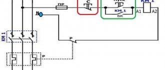
Another version of the electric motor control circuit is as follows (Fig. 4).
The NC (normally closed) contact of time relay K1, as well as the NC contact of relay K2, in the circuit of the short-circuit starter coil, is supplied with supply voltage.
After the short-circuit starter is turned on, the normally closed short-circuit contacts disengage the circuits of the K2 starter coil (prohibition of accidental activation). The short circuit contact in the power supply circuit of the starter coil K1 closes.
When the magnetic starter K1 starts, the K1 contacts close in the power circuit of its coil. The time relay turns on at the same time, the contact of this relay K1 in the short circuit starter coil circuit opens. And in the starter coil circuit K2 it closes.
When the short circuit starter winding is disconnected, the short circuit contact in the starter coil circuit K2 will close. After the K2 starter turns on, it opens the power circuit of the short-circuit starter coil with its K2 contacts.
In order to start the electric motor using a delta-star connection, various manufacturers produce special starting relays. These relays can have various names, for example, “start-delta” relay or “start time relay”, as well as some others. But the purpose of all these relays is the same.
Expert opinion
It-Technology, Electrical power and electronics specialist
Ask questions to the “Specialist for modernization of energy generation systems”
The principle of operation of an asynchronous motor and the connection diagram of the electric motor windings in a star or triangle. In order to reduce the starting currents, starting the electric motor is required in a certain sequence, namely. Ask, I'm in touch!
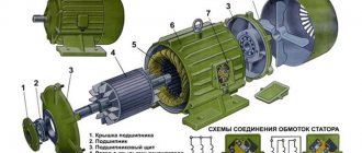
Connection diagrams
Let's start by looking at the design of a three-phase electric motor. Here we will be interested in three windings, which create a magnetic field that rotates the motor rotor. That is, this is exactly how the transformation of electrical energy into mechanical energy occurs.
There are two connection schemes:
- Star.
- Triangle.
Let’s immediately make a reservation that a star connection makes the unit start-up smoother. But at the same time, the power of the electric motor will be lower than the rated one by almost 30%. In this regard, the triangle connection wins. The motor connected in this way does not lose power.
But there is one nuance that concerns the current load. This value increases sharply at start-up, which negatively affects the winding. High current in copper wire increases thermal energy, which affects the wire's insulation. This can lead to breakdown of the insulation and failure of the electric motor itself.
I would like to draw your attention to the fact that a large amount of European equipment imported to the vast expanses of Russia is equipped with European electric motors that operate at 400/690 volts. By the way, below is a photo of the nameplate of such a motor.
So, these three-phase electric motors must be connected to the domestic 380V network only in a triangle diagram. If you connect a European motor with a star, it will immediately burn out under load.
Domestic three-phase electric motors are connected to a three-phase network according to a star circuit. Sometimes the connection is made in a triangle; this is done in order to squeeze out the maximum power from the motor, which is necessary for some types of technological equipment.
Manufacturers today offer three-phase electric motors, in the connection box of which the ends of the windings are made in the amount of three or six pieces. If there are three ends, this means that a star connection diagram has already been made inside the motor at the factory.
If there are six ends, then the three-phase motor can be connected to a three-phase network with both a star and a delta. When using a star circuit, it is necessary to connect the three ends of the beginning of the windings in one twist. Connect the other three (opposite) to the phases of the three-phase 380 volt supply network.
When using a triangle diagram, you need to connect all the ends together in order, that is, in series. The phases are connected to three points connecting the ends of the windings to each other. Below is a photo showing two types of connecting a three-phase motor.
Star-delta circuit
This connection scheme to a three-phase network is used quite rarely. But it exists, so it makes sense to say a few words about it. What is it used for? The whole point of such a connection is based on the position that when starting an electric motor, a star circuit is used, that is, a soft start, and for the main work a triangle is used, that is, the maximum power of the unit is squeezed out.
True, such a scheme is quite complicated. In this case, three magnetic starters must be installed in the connection of the windings. The first one is connected to the supply network on one side, and on the other side the ends of the windings are connected to it. The opposite ends of the windings are connected to the second and third. The second starter is connected with a triangle, and the third with a star.
Attention! The second and third starters cannot be turned on at the same time. A short circuit will occur between the phases connected to them, which will reset the machine. Therefore, a block is established between them. Essentially, everything will happen like this - when one is turned on, the contacts of the other open.
The operating principle is as follows: when the first starter is turned on, the temporary relay also turns on starter number three, that is, connected according to the star circuit. The electric motor starts smoothly. The time relay is activated for a certain period during which the motor will return to normal operation. After which starter number three is turned off, and the second element is turned on, transferring the triangle to the circuit.
Inverter with star/delta switching capability
Some converters operating with powerful motors have the ability to quickly switch the operating scheme. This is done in order to expand the range of engine speed adjustment upward from the nominal one. The method is based on the fact that a star connection provides higher torque at low speed, while a delta connection provides higher torque at high speed. You can set the output frequency at which switching occurs, the pause (delay) time for switching, and the motor parameters for the first and second modes.
Frequency converters of this type have outputs for switching on the corresponding contactors, ensuring the formation of the necessary switching circuits.
Diagram for connecting electric motor windings with a triangle
This is what a boron electric motor looks like and here the windings are connected by a triangle. Those. the end of the winding is connected to the beginning of the next winding.
Phase and line voltages are equal. Linear current is 1.73 times greater than phase current.
The total power formula will look like this:
If we pay attention to the formula for total power when connected by a star, we will notice that the formulas for total power are the same.
And to find the active power we apply the following formula:
where cosф is power factor, n is efficiency
From the active power formula we express the current:
The attentive reader should have noticed that the power formula is the same when connected by a triangle and when connected by a star. That’s right, just to maintain the required power, we will change the current.
But to prevent the motor from burning out when switching from delta to star, it is necessary to reduce the load on the motor shaft until the phase current becomes equal to the phase current when connected by a delta.
That is why they say that the power when connecting the electric motor windings with a star is less than when connecting with a delta.
Three-phase motor connection diagrams
Of the many schemes created by specialists, two methods are practically used for installing an asynchronous motor:
- Star diagram.
- Triangle diagram.
The names of the circuits are given according to the method of connecting the windings to the supply network. To determine on an electric motor which circuit it is connected to, you need to look at the specified data on a metal plate that is installed on the motor housing.
Even on old motor samples, it is possible to determine the method of connecting the stator windings, as well as the mains voltage. This information will be correct if the engine has already been in operation and there are no operational problems. But sometimes you need to make electrical measurements.
Star connection diagrams for a three-phase motor make it possible to start the motor smoothly, but the power is 30% less than the rated value. Therefore, in terms of power, the triangle circuit remains the winner. There is a feature regarding the current load. The current increases sharply during startup, this negatively affects the stator winding. The heat generated increases, which has a detrimental effect on the winding insulation. This leads to insulation failure and damage to the electric motor.
Many European devices supplied to the domestic market are equipped with European electric motors operating with voltages from 400 to 690 V. Such 3-phase motors must be installed in a 380 volt network of domestic voltage only using a triangular stator winding pattern. Otherwise, the motors will immediately fail. Russian motors for three phases are connected in a star. Occasionally, a delta circuit is installed to obtain the greatest power from the engine, used in special types of industrial equipment.
Manufacturers today make it possible to connect three-phase electric motors according to any circuit. If there are three ends in the mounting box, then the factory star circuit has been produced. And if there are six terminals, then the motor can be connected according to any circuit. When mounting in a star, you need to combine the three terminals of the windings into one unit. The remaining three terminals are supplied to phase power with a voltage of 380 volts. In a triangle circuit, the ends of the windings are connected in series in order to each other. Phase power is connected to the node points of the ends of the windings.
Checking the motor connection diagram
Let's imagine the worst case scenario for connecting the windings, when the wire terminals are not marked at the factory, the circuit assembly is carried out in the inside of the motor housing, and one cable is brought out. In this case, it is necessary to disassemble the electric motor, remove the covers, disassemble the internal part, and deal with the wires.
Stator phase determination method
After disconnecting the lead ends of the wires, use a multimeter to measure the resistance. One probe is connected to any wire, the other is brought in turn to all wire terminals until a terminal belonging to the winding of the first wire is found. Do the same for the other terminals. It must be remembered that marking the wires in any way is mandatory.
If there is no multimeter or other device available, then use homemade probes made from a light bulb, wires and batteries.
Winding polarity
To find and determine the polarity of the windings, you need to apply some techniques:
- Connect pulsed direct current.
- Connect an alternating current source.
Both methods operate on the principle of applying voltage to one coil and transforming it along the magnetic circuit of the core.
How to check the polarity of the windings with a battery and a tester
A voltmeter with increased sensitivity is connected to the contacts of one winding, which can respond to a pulse. Voltage is quickly connected to the other coil with one pole. At the moment of connection, the deviation of the voltmeter needle is monitored. If the arrow moves to the positive, then the polarity coincides with the other winding. When the contact opens, the arrow will go to minus. For the 3rd winding the experiment is repeated.
By changing the terminals to another winding when the battery is turned on, it is determined how correctly the markings of the ends of the stator windings are made.
AC test
Any two windings are connected in parallel with their ends to the multimeter. The voltage is turned on to the third winding. They look at what the voltmeter shows: if the polarity of both windings matches, then the voltmeter will show the voltage value, if the polarities are different, then it will show zero.
The polarity of the 3rd phase is determined by switching the voltmeter, changing the position of the transformer to another winding. Next, control measurements are made.
Star diagram
This type of three-phase motor connection circuit is formed by connecting the windings in different circuits, united by a neutral and a common phase point.
Such a circuit is created after the polarity of the stator windings in the electric motor has been checked. A single-phase voltage of 220V is supplied through a machine to the beginning of 2 windings. Capacitors are inserted into the gap into one: working and starting. The neutral power wire is connected to the third end of the star.
The capacitance value of capacitors (working) is determined by the empirical formula:
C = (2800 I) / U
For the starting circuit, the capacity is increased by 3 times. When the motor is operating under load, it is necessary to control the magnitude of the winding currents by measurements and adjust the capacitance of the capacitors according to the average load of the mechanism drive. Otherwise, the device will overheat and an insulation breakdown will occur.
It is best to connect the motor to operation through the PNVS switch, as shown in the figure.
It already contains a pair of closure contacts, which together supply voltage to 2 circuits by means of the “Start” button. When the button is released, the circuit breaks. This contact is used to start the circuit. A complete power shutdown is done by clicking on “Stop”.
Triangle diagram
The diagram for connecting a three-phase motor with a delta is a repetition of the previous version in startup, but differs in the method of connecting the stator windings.
The currents passing in them are greater than the values of the star circuit. The operating capacitances of capacitors require increased rated capacitances. They are calculated using the formula:
C = (4800 I) / U
The correct choice of capacitances is also calculated by the ratio of currents in the stator coils by measuring with a load.
Motor with magnetic starter
A three-phase electric motor operates through a magnetic starter in a similar circuit to a circuit breaker. This circuit additionally has an on and off block, with Start and Stop buttons.
One phase, normally closed, connected to the motor, is connected to the Start button. When it is pressed, the contacts close and current flows to the electric motor. It must be taken into account that when the Start button is released, the terminals will open and the power will turn off. To prevent this situation from happening, the magnetic starter is additionally equipped with auxiliary contacts, which are called self-retaining. They block the chain and prevent it from breaking when the Start button is released. You can turn off the power using the Stop button.
As a result, a 3-phase electric motor can be connected to a three-phase voltage network using completely different methods, which are selected according to the model and type of device, and operating conditions.
Connecting a motor from a machine
A general version of this connection diagram looks like in the figure:
Shown here is a circuit breaker that turns off the power supply to the electric motor in case of excessive current load and short circuit. The circuit breaker is a simple 3-pole circuit breaker with a thermal automatic load characteristic.
For an approximate calculation and assessment of the required thermal protection current, it is necessary to double the rated power of a motor designed to operate from three phases. The rated power is indicated on a metal plate on the motor housing.
Such connection diagrams for a three-phase motor may well work if there are no other connection options. The duration of the work cannot be predicted. This is the same if you twist an aluminum wire with a copper one. You never know how long it will take for the twist to burn out.
When using a connection diagram for a three-phase motor, you need to carefully select the current for the machine, which should be 20% greater than the operating current of the motor. Select the thermal protection properties with a reserve so that the blocking does not work during startup.
If, for example, the motor is 1.5 kilowatts, the maximum current is 3 amperes, then the machine needs at least 4 amperes. The advantage of this motor connection scheme is low cost, simple design and maintenance.
Connection methods and diagrams
Depending on the type of load used for the electric motor, its design features and characteristics, and the desired result, various connection schemes can be used. Most often, capacitors are used to connect a three-phase unit as a single-phase household load, but their number and method of putting them into operation depend on many parameters. Therefore, next we will look at various options for connecting electric motors.
Without capacitors
To connect an asynchronous electric motor to a 220V network, it is not at all necessary to use a capacitive element. Thanks to the development of semiconductor switches and circuits using them, you can avoid unnecessary power losses. For this, a transistor or dinistor switch is used.
Triangle capacitorless starting circuit
The above circuit is designed for starting electric motors with low speeds up to 1500 rpm and relatively low power.
The circuit works as follows:
- when voltage is applied to the input, the wires are connected to two points of the motor;
- voltage is supplied to the third point of the triangle through a timing RC circuit;
- the resistance store R1 and R2 regulates the shift interval by moving the slider;
- after the capacitor in the chain is saturated, dinistor VS1 passes a signal to open triac VS2.
If the connection of an electrical unit involves a large starting load and requires operation at high speeds - up to 3000 rpm, then it is necessary to use a similar electronic key circuit with two triacs and separate timing elements for each of them. But the windings of the electric machine will be connected according to an open star circuit. The operation of the scheme is similar to the previous one:
Capacitorless star starting circuit
With capacitors
Using capacitive elements to connect an electric motor is the most common method. For this, two capacitors are used, one of which is starting and the second is working. The starting voltage is introduced briefly, the additional capacitance allows you to increase the voltage shift in the corresponding winding and create more force.
Connection diagram with capacitors
As you can see from the figure above, a single-phase voltage is supplied to the electric motor between points L and N. The asynchronous motor IM is connected to them with two windings, and the same phase is connected to the third windings through the contacts of the push-button switch SA1 and SA2, which switch parallel-connected capacitors C1 and C2.
The asynchronous electric motor is switched on according to the following principle:
- By pressing the Start button, two pairs of contacts are set in motion - SA1 and SA2, after which electric current begins to flow in the windings;
- After the button is released, contact SA2 remains closed, supplying a biased phase through capacitor C1, and SA1 opens, removing the starting capacitor C2 from the circuit;
- The starting characteristics return to nominal and the engine operates normally.
But with this connection of an asynchronous motor to a 220V network, the rotor will rotate in only one direction. Therefore, to perform reverse movements, you will need to completely sort out the connection points or use another method.
With reverse
Some technological operations require forward and reverse rotation of the motor shaft, so the connection must change the sequence of voltage alternation on the windings. Of course, it is impractical to perform such operations manually, especially when changing direction is performed several times an hour.
Therefore, it is much more efficient to reverse the electric motor through a switch with two pairs of contacts having opposite logic. This could be a toggle switch or rotary switch included in the circuit instead of a regular button:
Switching on a three-phase motor with reverse
As you can see in the figure, the connection principle is no different from the considered circuit with a capacitor, with the only difference being that the SA switch has two stable positions. In one case, it supplies voltage to the capacitors from the phase, in the second from the neutral conductor. Therefore, the alternation of windings is reversed by simply switching the toggle switch.
Using a starter
If the electric motor creates a large starting and operating load during operation, then it is better to connect it through a magnetic starter or contactor. Which will ensure reliable switching and subsequent protection of the electrical machine from emergency situations.
Switching circuit via a magnetic starter
As you can see in the diagram, switching is carried out by pressing the Start button, which closes the starter coil control circuit and supplies voltage to the Descent starting capacitor. When current flows through the starter coil K1, its contacts K1.1 and K1.2 close. The first ones are designed to close the supply line of the electric motor. The latter bypass the Start button, which returns to the off state and opens the power supply circuit to the starting capacitor.
Connecting an asynchronous motor
The three-phase asynchronous electric motor and the connection diagram depend on your needs. The most common option is a direct connection circuit; for motors connected by a delta circuit, a star connection circuit with a transition to a delta connection is possible; if necessary, a reverse connection option is possible.
In our article we will look at the most popular direct connection and direct connection circuits with the possibility of reverse.
Scheme of direct connection of an asynchronous electric motor
In previous chapters, we connected the motor windings, and now it’s time to connect it to the network. Motors must be connected to the network using a magnetic starter, which ensures reliable and simultaneous activation of all three phases of the electric motor.
The starter, in turn, is controlled by a push-button station - the same “Start” and “Stop” buttons in one housing.
Note! Instead of a machine, it is quite possible to use fuses. Only their rated current must correspond to the rated current of the motor. It must also take into account the starting current, which for different types of motors ranges from 6 to 10 times the rated one.
- Now let's proceed directly to the connection. It can be roughly divided into two stages. The first is connecting the power section, and the second is connecting the secondary circuits. Power circuits are circuits that provide connection between the engine and a source of electrical energy. Secondary circuits are necessary for ease of engine control.
- To connect the power circuits, we just need to connect the motor output with the first terminals of the starter, the starter terminals with the terminals of the circuit breaker, and the machine itself with a source of electrical energy.
Note! Connecting the phase outputs to the contacts of the starter and the machine does not matter. If after the first start we determine that the rotation is incorrect, we can easily change it. The engine grounding circuit is connected in addition to all switching devices.
Now let's look at a more complex secondary circuit diagram. To do this, first of all, as in the video, we need to decide on the nominal parameters of the starter coil. It can be 220V or 380V.
- You should also deal with such an element as the starter block contacts. This element is available on almost all types of starters, and in some cases it can be purchased separately with subsequent installation on the starter body.
- These block contacts contain a set of contacts - normally closed and normally open. Let us warn you right away - don’t be alarmed, there is nothing complicated about this. A normally closed contact is a contact that is closed when the starter is in the off position. Accordingly, the normally open contact is open at this moment.
- When the starter is turned on, the normally closed contacts open and the normally open contacts close. If we are talking about a three-phase asynchronous electric motor and connecting it to the electrical network, then we need a normally open contact.
- There are also such contacts on the push-button post. The Stop button has a normally closed contact, and the Start button has a normally open contact. First we connect the “Stop” button.
- To do this, we connect one wire to the starter contacts between the circuit breaker and the starter. We connect it to one of the contacts of the “Stop” button. There should be two wires coming off the second contact of the button at once. One goes to the contact of the “Start” button, the second to the block contacts of the starter.
- From the “Start” button we lay a wire to the starter coil, and we also connect the wire from the starter block contacts there. We connect the second end of the starter coil either to the second phase wire on the power contacts of the starter, when using a 380V coil, or it is connected to the neutral wire, when using a 220V coil.
- That's it, our direct connection circuit for an asynchronous motor is ready for use. After the first turn on, we check the direction of rotation of the motor and if the rotation is incorrect, then simply swap the two power wires at the starter terminals.
Electric motor reversal circuit diagram
A common option for connecting an asynchronous electric motor is the option using reverse. This mode may be required in cases where it is necessary to change the direction of rotation of the engine during operation.
- To create such a circuit, we will need two starters, which is why the price of such a connection increases slightly. One will turn on the engine in one direction, and the second in the other. A very important point here is the inadmissibility of turning on both starters at the same time. Therefore, we need to provide blocking from such inclusions in the secondary circuit.
- But first, let's connect the power section. To do this, as in the above option, we connect the starter from the machine, and the motor from the starter.
- The only difference will be the connection of another starter. We connect it to the inputs of the first starter. In this case, an important point will be to swap the two phases, as in the photo.
- We simply connect the output of the second starter to the output of the first. And here we don’t change anything anymore.
- Well, now, let's move on to connecting the secondary circuit. It all starts again with the “Stop” button. We connect it to one of the incoming contacts of the starter - it doesn’t matter the first or second. From the “Stop” button we again have two wires. But now one is to pin 1 of the Forward button, and the second is to pin 1 of the Back button.
- The further connection is made using the “Forward” button; using the “Back” button it is identical. To contact 1 of the “Forward” button we connect the contact of the normally open contact of the starter block contacts. Pun, but you can't say it more precisely. To contact 2 of the “Forward” button we connect the wire from the second contact of the starter block contacts.
- We also connect a wire there that will go to the normally closed contact of the starter block contacts number two. And from this block contact it is connected to the starter coil number 1. The second end of the coil is connected to the phase or neutral wire, depending on the voltage class.
- The coil of the second starter is connected in the same way, only we connect it to the block contacts of the first starter. This is what ensures blocking from turning on one starter while the second one is pulled up.
votes
Article rating
Star-Triangle
Switching the motor from star to delta is used to protect electrical circuits from overloads. Mostly powerful three-phase asynchronous motors from 30-50 kW, and high-speed ones ~3000 rpm, sometimes 1500 rpm, are switched from star to delta.
It is known that when the electric motor starts, its current increases up to 7 times. A squirrel-cage induction motor resembles a transformer with a short-circuited secondary winding.
If the engine is connected in a star, then a voltage of 220 Volts is supplied to each of its windings, and if the engine is connected in a triangle, then a voltage of 380 Volts is supplied to each of its windings. Here Ohm’s law “I=U/R” comes into play; the higher the voltage, the higher the current, but the resistance does not change.
Simply put, when connected to a delta (380), the current will be higher than when connected to a star (220).
When the electric motor accelerates and reaches full speed, the picture completely changes. The fact is that the engine has power that does not depend on whether it is connected to a star or a delta. Engine power depends largely on the iron and wire cross-section. Another law of electrical engineering “W=I*U” applies here.
Power is equal to current multiplied by voltage, that is, the higher the voltage, the lower the current. When connected to a delta (380), the current will be lower than to a star (220).
Let's get to practice
In the engine, the ends of the windings are brought out to the “terminal block” in such a way that, depending on how you place the jumpers, you will get a star or delta connection as shown in the figure. Such a diagram is usually drawn on the lid.
In order to switch from star to delta, we will use magnetic starter contacts instead of jumpers.
Let's look at the power section diagram, shown in thick lines.
Magnetic starter P1 is used to turn the motor on and off. The contacts of the magnetic starter P2 work as jumpers to turn on the asynchronous motor in a triangle. Please note that the wires from the motor terminal block must be connected in the same order as in the motor itself, the main thing is not to confuse them. I will repeat once again this is the most important thing in the circuit. CONTACTS P2 PERFORM THE ROLE OF JUMPERS FOR CONNECTING INTO A TRIANGLE.
Magnetic starter P3 connects star jumpers to one half of the terminal block, and voltage is applied to the other half.
Let's look at the control diagram using thin lines.
When you press the “START” button, power is supplied to the magnetic starter P1; it is triggered and voltage is supplied to it through the contact block; now the button can be released. Next, voltage is supplied to the RT time relay, it counts the set time. Also, voltage through the closed contact of the time relay P1 is supplied to the magnetic starter P3 and the engine starts in the “star” .
After the set time, the RT time relay is activated. Magnetic starter P3 is turned off. Voltage through the time relay contact is supplied to the normally closed (closed in the off position) block contact of the magnetic starter P3, and from there to the coil of the magnetic starter P2. And the electric motor is switched into a triangle . By the way, it is not shown in the diagram, but the P3 starter should also be connected through a normally closed block contact of the P2 starter, to protect against the simultaneous activation of the starters.
It is better to take double magnetic starters P2 and P3 with a mechanical lock for simultaneous activation.
The “STOP” button turns off the circuit; in series with this button you can connect “limit switches”, “emergency lights”, and so on.
If the network voltage is 220/380, then the motor should be 380/660
Power of a three-phase motor in a single-phase network
Three-phase motor in a single-phase network