Design features and principle of operation
In fact, a commutator motor is a rather specific device that has all the advantages of a DC machine and, therefore, has similar characteristics.
The difference between these motors is that the stator housing of the AC motor is made from separate sheets of electrical steel to reduce eddy current losses. The excitation windings of the machine are connected in series to optimize operation in a 220V household network. They can be either single- or three-phase; due to the ability to operate on direct and alternating current, they are also called universal. In addition to the stator and rotor, the design includes a brush-commutator mechanism and a tachogenerator. The rotation of the rotor in a commutator motor occurs as a result of the interaction of the armature current and the magnetic flux of the field winding. Through the brushes, current is supplied to a commutator assembled from trapezoidal plates and is one of the rotor units connected in series to the stator windings.
In general, the principle of operation of a commutator motor can be clearly demonstrated using the experiment known from school with the rotation of a frame placed between the poles of a magnetic field. If current flows through the frame, it begins to rotate under the influence of dynamic forces. The direction of movement of the frame does not change when the direction of current movement in it changes.
Connecting the field windings in series gives a large maximum torque, but high idle speeds appear, which can lead to premature failure of the mechanism.
Basic parameters of a DC motor
Torque constant
For a DC commutator motor, the torque constant is determined by the formula:
see also
Basic parameters of a DC motor
Key Parameters of DC Motor
- Torque constant
- Constant EMF
- Motor constant
- Mechanical Rigidity
- Motor voltage
- Mechanical time constant
Basic parameters of the electric motor
- Motor torque
- Motor power
- Efficiency
- Rated speed
- Rotor moment of inertia
- Rated voltage
- Electrical time constant
Bibliography
Expert opinion
It-Technology, Electrical power and electronics specialist
Ask questions to the “Specialist for modernization of energy generation systems”
Advantages and disadvantages The working one has the lowest resistance, the average value is the starting winding, and the highest is the total output; the resistance of two windings connected in series is measured. Ask, I'm in touch!
Simplified connection diagram
A typical connection diagram can include up to ten output contacts on a terminal strip. The current from phase L flows to one of the brushes, then is transmitted to the commutator and armature winding, after which the second brush and jumper pass to the stator windings and exits to neutral N. This connection method does not provide for motor reversal due to the fact that series connection of the windings leads to simultaneous replacement of the poles of magnetic fields and as a result the moment always has one direction.
The direction of rotation in this case can be changed only by swapping the positions of the winding outputs on the contact strip. The motor is switched on “directly” only with the stator and rotor leads connected (via a brush-commutator mechanism). The output of half the winding is used to turn on the second speed. It should be remembered that with this connection the motor operates at full power from the moment it is turned on, so it can be operated for no more than 15 seconds.
Types of CD
It is customary to classify these devices according to the type of power supply; depending on this, two groups of CDs are distinguished:
- Direct current. Such machines are characterized by high starting torque, smooth speed control and a relatively simple design.
- Universal. They can operate from both constant and variable power sources. They are distinguished by their compact size, low cost and ease of management.
The first ones are divided into two subtypes; depending on the organization of the inductor, it can be on permanent magnets or special excitation coils. They serve to create the magnetic flux necessary to generate torque. CDs, where excitation coils are used, are distinguished by types of windings, they can be:
- independent;
- parallel;
- consistent;
- mixed.
Having dealt with the types, let's consider each of them.
Universal type CD
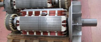
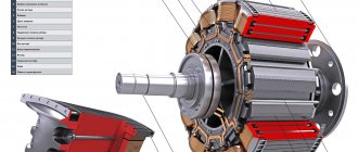
The figure below shows the appearance of an electric machine of this type and its main structural elements. This design is typical for almost all CDs.
Design of a universal commutator motor
Designations:
- A is a mechanical commutator, it is also called a collector, its functions were described above.
- B – brush holders, used to attach brushes (usually made of graphite), through which voltage is supplied to the armature windings.
- C – Stator core (made up of plates, the material for which is electrical steel).
- D – Stator windings, this unit belongs to the excitation system (inductor).
- E – Armature shaft.
For devices of this type, excitation can be serial or parallel, but since the latter option is not currently produced, we will not consider it. As for universal sequential excitation CDs, a typical diagram of such electric machines is presented below.
Scheme of a universal commutator motor
Features and scope of universal CDs
The main disadvantages of this device appear when it is connected to AC voltage sources, which is reflected in the following:
- decrease in efficiency;
- increased sparking in the brush-collector unit, and as a result, its rapid wear.
Previously, CDs were widely used in many household electrical appliances (tools, washing machines, vacuum cleaners, etc.). At the moment, manufacturers have practically stopped using this type of motor, giving preference to brushless electric machines.
Now let's look at collector electric machines operating from constant voltage sources.
CD with permanent magnet inductor
Structurally, such electric machines differ from universal ones in that permanent magnets are used instead of excitation coils.
Design of a permanent magnet commutator motor and its diagram
This type of CD is most widespread compared to other electric machines of this type. This is due to the low cost due to the simplicity of the design, simple control of the rotation speed (depending on voltage) and changing its direction (it is enough to change the polarity). The motor power directly depends on the field strength created by the permanent magnets, which introduces certain restrictions.
The main area of application is low-power drives for various equipment, often used in children's toys.
CD on permanent magnets from a toy from the times of the USSR
The advantages include the following qualities:
- high torque even at low speed;
- dynamic management;
- low cost.
Main disadvantages:
- low power;
- magnets lose their properties due to overheating or over time.
Engine control
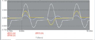
In practice, engines are used with various methods of regulating operation. The commutator motor can be controlled using an electronic circuit in which the role of a regulating element is played by a triac, which “passes” a given voltage to the motor. A triac works like a fast-acting switch, the gate of which receives control pulses and opens it at a given moment.
In circuits using a triac, an operating principle based on full-wave phase control is implemented, in which the amount of voltage supplied to the motor is tied to the pulses arriving at the control electrode. The frequency of rotation of the armature is directly proportional to the voltage applied to the windings. The operating principle of the commutator motor control circuit is simplistically described by the following points:
- the electronic circuit sends a signal to the triac gate,
- the shutter opens, current flows through the stator windings, giving rotation to the motor armature M,
- the tachogenerator converts instantaneous rotation speed values into electrical signals, resulting in feedback with control pulses,
- as a result, the rotor rotates evenly under any load,
- Reversing the electric motor is carried out using relays R1 and R
In addition to the triac, there is a phase-pulse thyristor control circuit.
With field windings
DC motors with excitation windings have found wider application. This type of engine powers cordless power tools: angle grinders, drills, screwdrivers, etc. The field windings are made of insulated copper wire (in a varnish sheath). The grooves in the pole pieces are used as a basis. Windings are wound on them as a base.
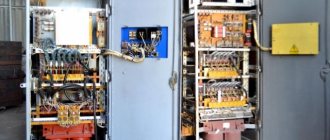
Commutator motor with winding excitation system
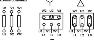
If we look at the design of a commutator motor, we see two unrelated devices, the rotor and the field windings. The characteristics and properties of the engine depend on the method of their connection. There are four ways to connect the rotor and field windings. These methods are called excitation methods. Here they are:
- Independent. This is only possible if the voltages on the field winding and the armature are unequal (this happens very rarely). If they are equal, a parallel excitation circuit is used.
- Parallel. Speed is well regulated, stable operation at low speeds, constant characteristics, independent of time. The disadvantages of this type of connection include instability of the motor when the inductor current drops below zero.
- Consistent. With this connection, you cannot turn on the motor with a shaft load below 25% of the nominal one. When there is no load, the rotation speed increases greatly, which can destroy the engine. Therefore, this type of connection is not used with a belt drive; if the belt breaks, the motor is destroyed. The series drive circuit has high torque at low speeds, but does not work very well at high speeds, making it difficult to control the speed.
- Mixed. Considered one of the best. Handles well, has plenty of low-end torque, and rarely gets out of control. Among the disadvantages is the highest price compared to other types.
Methods for connecting field windings
Brushed DC motors can have an efficiency from 8-10% to 85-88%. Depends on the connection type. But high-performance ones are characterized by high speeds (thousands of revolutions per minute, less often hundreds) and low torque, so they are ideal for fans. For any other equipment, low-speed models with low efficiency are used, or a gearbox is added to productive models; no other solution has yet been found.
Advantages and disadvantages
The undeniable advantages of such machines include:
- compact dimensions,
- increased starting torque, “versatility”, operation on alternating and direct voltage,
- speed and independence from network frequency,
- soft adjustment of speed over a wide range by varying the supply voltage.
The disadvantage of these engines is considered to be the use of a brush-commutator junction, which causes:
- decreased durability of the mechanism,
- sparking between the commutator and brushes,
- increased noise level,
- a large number of collector elements.
Typical faults
The brush-commutator mechanism requires the greatest attention, in which sparking is observed even when the new engine is running. Worn out brushes should be replaced to prevent more serious problems: overheating of the commutator lamellas, their deformation and peeling. In addition, an interturn short circuit of the armature or stator windings may occur, which results in a significant drop in the magnetic field or strong sparking of the commutator-brush junction.
Premature failure of a universal commutator motor can be avoided by proper operation of the device and the professionalism of the manufacturer during the assembly process of the product.