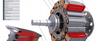
Operating principle.
The operation of this motor directly depends on the interaction of the magnetic fields of the stator and collector. As you and I already know, there are windings in the stator and on the collector. If voltage is applied to these windings, magnetic fields will be created due to this. And these magnetic fields will force the collector to rotate. See how it is shown in the picture.
Advantages and disadvantages.
Main advantages of DBT:
1. Simple engine design.
2. The shaft rotation speed can be changed very easily.
3. Due to the strong torque, very good starting characteristics.
4. Can be used both as a motor and as a generator.
5. Compared to some other engines, it is not large in size.
Flaws:
1. Very high price.
2. If you connect the motor to an alternating network, then rectifier devices are also needed.
3. Very often it is necessary to service the commutator-brush assembly.
4. The manifold has a limited service life due to wear.
§36. Regulating the rotation speed of the electric motor armature
From formula (65) it follows that the rotation frequency of the armature of a DC electric motor depends on the voltage drop Iа? Rя in the armature winding circuit, the supply voltage U and the magnetic flux Ф. Therefore, it can be adjusted in three ways:
inclusion of a rheostat with resistance Rп in the armature winding circuit;
changing the supply voltage U;
change in magnetic flux F.
Let us consider these methods in more detail using motors with series and parallel excitation as an example.
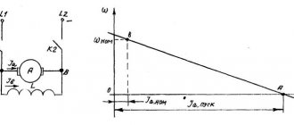
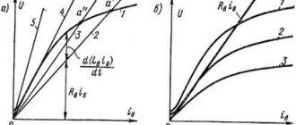
Inclusion of a rheostat in the armature winding circuit. When a rheostat with resistance Rп is connected to the armature winding circuit, in addition to the natural mechanical characteristic 1, a number of rheostatic characteristics 2, 3 and 4 are also obtained (Fig. 133). In this case, the given load torque Mvn corresponds to different values of rotation speed n1, n2, n3 and n4; the greater the resistance Rп, the lower the rotation speed of the motor armature. This control method is very simple and allows for smooth control of the rotation speed over a wide range. (However, this results in large energy losses in the control rheostat, as a result of which it is practically used only during short-term operating modes of the engine (for example, during startup). Another disadvantage of the control method under consideration is that the rotation speed n can only be reduced from n1 to zero.
Change in supply voltage. When the supply voltage changes, the rotation speed n changes in proportion to U. Consequently, by applying different voltages U1, U2, U3 to the armature winding, a family of mechanical characteristics can be obtained.
Rice. 133. Mechanical characteristics of electric motors with series (a) and independent or parallel (b) excitation when regulating the rotation speed by including a rheostat in the armature winding circuit
Rice. 134. Mechanical characteristics of an electric motor with sequential (a) and independent (b) excitation when regulating the rotation speed by changing the supply voltage
Rice. 135. Power supply circuits for an electric motor with sequential excitation from a generator (a) and a rectifier (b)
ristik 1, 2 and 3, for which at any load n1:n2:n3 = U1:U2:U3 (Fig. 134). When the supply voltage decreases, the mechanical characteristics of the engine shift to the region of lower rotation speeds and are located in parallel. To implement this method of regulating the rotation speed, the engine must be connected to a direct current source with adjustable voltage: to a generator T with independent excitation (Fig. 135, a) or a rectifier Bn (Fig. 135, b). Traction motors are powered from a generator on diesel locomotives, and from a rectifier on electric locomotives and AC electric trains. On electric locomotives and electric trains, the rectifier is connected to a transformer, which allows you to change the voltage supplied to the input of the rectifier, and therefore its output voltage U. On diesel locomotives, the control circuits have special electrical equipment that allows you to change the excitation current of the generator, i.e. its output voltage U, manually or automatically.
Despite the fact that the considered method requires rather complex equipment, it is widely used on modern locomotives and electric trains, since it provides smooth and economical (without energy loss in rheostats) control of the rotation speed over a very wide range. It should be noted that for electric motors with parallel excitation, this control method cannot be used, since if the supply voltage were reduced, the magnetic flux of the motor would correspondingly decrease and the armature winding current would increase. In this case, the engine must be switched to independent excitation.
On e. p.s. DC voltage supplied from the contact network to an electric locomotive or motor car cannot be adjusted, therefore, here, to change the voltage supplied to the motors, series-parallel switching of traction motors is used. This changes the voltage applied to each locomotive engine and the rotational speed.
When regulating the engine speed by switching them in series-parallel, the number of possible connection schemes depends on the number of engines installed on a given locomotive. For example, on four-axle electric locomotives a series connection of traction motors can be used (Fig. 136, a); in this case, the voltage supplied to the motor is 4 times less than the voltage U in the contact network and the motor has a certain minimum rotation speed nmin at a given torque Mvn. When connecting the motors into two parallel groups (Fig. 136, b), each of which includes two series-connected motors, the voltage supplied to each motor will be 2 times less than the voltage U in the contact network and its rotation speed will be 2nmin . The characteristics of the engines are located one above the other (Fig. 136, c).
Series-parallel switching of traction motors is also used on diesel locomotives. This allows you to limit the voltage regulation range of the generator, which determines its overall dimensions and weight.
Change in magnetic flux. In order to change the magnetic flux F, regulate the motor excitation current using
Rice. 136. Connection diagrams for traction motors on four-axle electric locomotives or electric trains (a and b) and mechanical characteristics of motors for various connection schemes (c): 1 - series connection; 2—serial-parallel connection
Rice. 137. Scheme for connecting an adjusting rheostat parallel to the excitation winding in a motor with series excitation (a) and mechanical characteristics (b) at different rheostat resistances
adjusting rheostat Rрв (Fig. 137, a). In motors with sequential excitation, the adjusting rheostat is connected in parallel to the excitation winding, as a result of which only part of the armature current will flow through the excitation winding (the other part branches off at point O into the rheostat Rрв). Typically, the control rheostat has several stages with resistances R1, R2, R3, which make it possible to obtain several stages of regulation of the motor excitation current.
Stages R1, R2, R3 are switched on by contactors 1, 2 and 3; in this case, the mechanical characteristics of the engine 2 (when stage R1 is turned on), 3 (when R1 and R2 are turned on, and 4 (when R1, R2 and R3 are turned on) are located above the natural characteristic 1 (Fig. 137, b).
The degree of regulation of the excitation current is characterized by the excitation regulation coefficient ?, which is the ratio of the excitation current Iв0 with weakened excitation (the control rheostat Rрв is turned on) to the excitation current Iвн with normal excitation at the same current in the armature winding:
? = Iin0/Iin = Rin/(Rin+Rin)
where Rв is the resistance of the excitation winding.
The considered control method is simple and economical, therefore it is widely used on locomotives and electric trains. However, in this case, the rotation speed can be controlled only within a relatively small range. The lower limit nmin is limited by the saturation of the magnetic circuit of the machine, which does not allow the magnetic flux to increase significantly, the upper limit nmax is limited by stability conditions (with a strong decrease in F, the motor goes into overdrive), as well as by the fact that with a deep weakening of the excitation, the armature current Iа greatly increases, which leads to an increase in reactive e. d.s. and the distorting effect of the anchor reaction. This increases the risk of sparking on the collector and the appearance of a circular fire. For this reason, motors designed to operate in deep excitation weakening modes must have a compensation winding and a reduced value of reactive e. d.s. at nominal mode. Usually the limiting value of the excitation coefficient is ? for motors without a compensation winding it is 0.3-0.33, and with a compensation winding - 0.2.
In motors with independent and parallel excitation, the adjusting rheostat, by means of which the excitation current Iв and magnetic flux Ф are changed, is connected in series with the excitation winding (see Fig. 125). In this case, when the excitation current changes, the rotation speed n0 at idle will change, i.e., mechanical characteristic 2 with weakened excitation will be located above characteristic 1 with normal excitation (Fig. 138). However, characteristics 1 and 2 at different values of Ф will not be parallel, since according to formula (65) the reduction in rotational speed, caused by the voltage drop Iа? Rа in the armature winding circuit, changes.
Operation of an electric motor with weakened excitation during transient processes . When the control rheostat is turned on in parallel with the field winding (see Fig. 137, a), special measures must be taken to maintain the required current distribution between it and the rheostat during transient processes that occur in cases of a sudden change in the operating mode of the engine, a change in voltage in the contact network, etc.
During transient processes, when the currents Iа, Iв and Iрв change, a significant emission occurs in the excitation winding. d.s. self-induction eL. As a result of its action, the current Iv decreases compared to its value in stationary mode, and the current Irv increases, i.e., a significantly greater weakening of excitation occurs. The most dangerous transient process for traction motors operating with weakened excitation is their inclusion at full voltage after a short-term disconnection from
Rice. 138. Mechanical characteristics of an electric motor with independent and parallel excitation when regulating the rotation speed by changing the magnetic flux
Rice. 139. The direction of the electromagnetic moment M with different directions of current in the armature winding and different polarities of the poles
Rice. 140. Switching diagrams for the winding of an electric motor with sequential excitation when changing the direction of rotation
network (when the pantograph is separated from the contact wire). In this case, due to the large e. d.s. self-induction eL at the first moment after switching on, almost all of the current Iya will flow through the control rheostat Rрв, and the current Iв in the excitation winding will be small. This will lead to a significant increase in current Iya in the armature winding due to a decrease in e. d.s. E induced in it. In practice, under these conditions, a sharp surge of current Ia occurs, accompanied by a disruption of normal commutation (sparking under the brushes) and the formation of a circular fire. In addition, due to the high rate of change in current, large switching overvoltages are created, which can cause breakdown of the insulation of the armature and excitation windings.
The inrush current Iа when the motor is turned on under voltage and the rate of its change depend on the distribution of currents Iв and Iрв between the excitation winding and the adjusting rheostat Rрв. To ensure during transient processes the same distribution of currents Iv and Irv as in stationary mode, an inductive shunt ISh, which is a coil with a ferromagnetic core, is connected in series with the rheostat Rrv. The inductance of this coil is selected so that the ratio of the inductances of the excitation winding and the rheostat circuit Rрв is approximately equal to the ratio of their resistances. Under this condition, e.g. arising during transient processes. d.s. self-induction eL in the excitation winding and eL1 in the inductive shunt will not affect the distribution of currents Iв and Iрв and the increase in current Iа will be small.
Changing the direction of rotation. To change the direction of rotation of the motor, it is necessary to change the direction of the electromagnetic moment M acting on the armature. The direction of the moment M is determined by the left-hand rule (see Fig. 68, b). You can change the direction of M in two ways (Fig. 139, a - c): 1) changing the direction of the current Iya in the armature winding; 2) changing the polarity of the poles, i.e. the direction of the magnetic flux Ф, by changing the direction of the excitation current Iв. To do this, switch the wires supplying current to the armature winding or to the field winding. For example, if when the electric motor rotates in the Forward direction, the current Ia passes from brush A to brush B (Fig. 140, a), and the excitation current Ib passes from terminal B1 to terminal B2, then to move the motor in the Reverse direction it is necessary to switch the armature winding circuit so that current Iа passes from brush B to brush A, leaving the direction of current Iв unchanged (Fig. 140, b), or, leaving the direction of current Iа unchanged from A to B, switch the excitation circuit so that current Iв passes from terminal B2 to clamp B1 (Fig. 140, c).
Application.
DC motors are widely used in various equipment. Such as: cranes, excavators, trams, electric trains, diesel locomotives, motor ships and so on. Also, such engines are used in power tools. In production, they can be found on machines where it is necessary to regulate the rotation speed over a very wide range.
That's all I have. The article was not very voluminous, but for the general concept it was quite informative. If you have questions, ask them in the comments, click on the social media buttons and subscribe to updates. Bye.
Sincerely, Alexander!
PWM
The simplest method of controlling the rotation speed of a DC motor is based on the use of pulse width modulation (PWM or PWM). The essence of this method is that the supply voltage is supplied to the motor in the form of pulses. In this case, the pulse repetition rate remains constant, but their duration can vary.
The PWM signal is characterized by such a parameter as the duty cycle or duty cycle. This is the reciprocal of the duty cycle and is equal to the ratio of the pulse duration to its period.
D = (t/T) * 100%
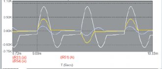
The figures below show PWM signals with different duty cycles.
With this control method, the motor rotation speed will be proportional to the duty cycle of the PWM signal.
The simplest DC motor control circuit consists of a field-effect transistor, the gate of which is supplied with a PWM signal. The transistor in this circuit acts as an electronic switch that switches one of the motor terminals to ground. The transistor opens at the moment of the pulse duration.
How will the engine behave when turned on like this? If the frequency of the PWM signal is low (several Hz), the motor will turn jerkily. This will be especially noticeable with a small duty cycle of the PWM signal. At a frequency of hundreds of Hz, the motor will rotate continuously and its rotation speed will change in proportion to the duty cycle. Roughly speaking, the engine will “perceive” the average value of the energy supplied to it.
There are many circuits for generating a PWM signal. One of the simplest is a circuit based on a 555 timer. It requires a minimum of components, requires no setup and can be assembled in one hour.
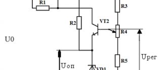
The supply voltage of the VCC circuit can be in the range of 5 - 16 Volts. Almost any diodes can be used as diodes VD1 - VD3. If you are interested in understanding how this circuit works, you need to refer to the block diagram of the 555 timer. The timer consists of a voltage divider, two comparators, a flip-flop, an open collector switch and an output buffer.
The power supply (VCC) and reset pins are connected to the power supply plus, say +5 V, and the ground pin (GND) to the minus. The open collector of the transistor (DISC pin) is connected to the power supply positive through a resistor and the PWM signal is removed from it. The CONT pin is not used; a capacitor is connected to it. The THRES and TRIG comparator pins are combined and connected to an RC circuit consisting of a variable resistor, two diodes and a capacitor. The middle pin of the variable resistor is connected to the OUT pin. The extreme terminals of the resistor are connected through diodes to a capacitor, which is connected to the ground with the second terminal. Thanks to this inclusion of diodes, the capacitor is charged through one part of the variable resistor and discharged through the other. At the moment the power is turned on, the OUT pin is at a low logical level, then the THRES and TRIG pins, thanks to the VD2 diode, will also be at a low level. The upper comparator will switch the output to zero, and the lower one to one. The output of the trigger will be set to zero (because it has an inverter at the output), the transistor switch will close, and the OUT pin will be set to a high level (because it has an inverter at the input). Next, capacitor C3 will begin to charge through diode VD1. When it charges to a certain level, the lower comparator will switch to zero, and then the upper comparator will switch the output to one. The trigger output will be set to a unity level, the transistor switch will open, and the OUT pin will be set to a low level. Capacitor C3 will begin to discharge through diode VD2 until it is completely discharged and the comparators switch the trigger to another state. The cycle will then repeat. The approximate frequency of the PWM signal generated by this circuit can be calculated using the following formula:
F = 1.44/(R1*C1), [Hz]
where R1 is in ohms, C1 is in farads. With the values indicated in the diagram above, the frequency of the PWM signal will be equal to:
F = 1.44/(50000*0.0000001) = 288 Hz.
Let's combine the two circuits presented above, and we get a simple DC motor speed controller circuit, which can be used to control the engine speed of a toy, robot, micro drill, etc.
VT1 is an n-type field-effect transistor capable of withstanding the maximum motor current at a given voltage and shaft load. VCC1 is from 5 to 16 V, VCC2 is greater than or equal to VCC1. Instead of a field-effect transistor, you can use a bipolar npn transistor, a Darlington transistor, or an opto-relay of appropriate power.