Another homemade product for those who are bored at home
I needed a couple of antennas for digital, in places with “not the best reception”... I went shopping (this was before self-isolation - if it’s relatively budget-friendly, then it’s complete G. The more expensive one looks decent, but how it works is questionable.
I decided to make something homemade. It was somehow awkward to “twist” an antenna from a piece of cable (although rumor has it it works) - I wanted something simple, but more decent and advanced
In fact, the one I made is not radically more complicated, but somehow more “solid” or something. And the results of its testing were very encouraging, so I decided to sketch out a short description of what and how, in case someone else finds it useful
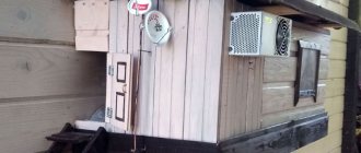
... even if my street cats have a “normal” antenna on their house, what can you do without an antenna?!
The wire is not all finished yet, now we’ll assemble something!
In the places described, I previously used home-made broadband log-periodic antennas, probably since the “beginning of perestroika.” They worked well in analog and not only on UHF, but “for some reason, digital was too tough for them.” I didn’t really delve into the essence of the reasons, I removed them and began to think about what to replace them with. Here is one of them, waiting for a place in the trash
A little history
In the early 60s of the last century, our compatriot Kharchenko K.P. developed a simple flat zigzag antenna with good characteristics.
Copyright certificate No. 138277 for an invention called “Band directional antenna” was issued to Konstantin Pavlovich Kharchenko in 1961 (according to his application dated June 16, 1960). In the same year, materials were published in the magazine “Radio” for repetition by radio amateurs.
The antenna is not critical to materials and dimensions during manufacturing, has a simple good match with the reduction cable, and it successfully combines multiple elements of a common-mode antenna array with a single feed point.
Theory and calculations
The described antenna, in theory, has a horizontal “figure-of-eight” radiation pattern and a relatively high gain, which can be further increased by using a reflector/reflector.
To obtain maximum gain on all channels, it is necessary to make an antenna approximately in the middle of the range between the multiplexes used.
Finding (for calculations) the frequencies of multiplexes used in your region is easy,
for example, a request like “dvb-t2 channel frequencies” + “Krasnodar”
I found something like this:
The middle, between “my” two multiplexes, is 700 MHz - we will calculate the antenna at this frequency.
As a basis for calculating the dimensions of the antenna, we take the drawing of its author
Calculate the wavelength: λ = 300 / f [m]
300/700 = 0.428m, approximately 43cm length of each side of the rhombus
λ/4
=43/4= 10.75
The total length of the material we need (11cm*8=88cm) is less than a meter. The distance between the reduction contacts, where we will solder the cable, is 10-12mm (the standard value for this antenna for frequencies below 900 MHz).
I will make a simple antenna, without a reflector, however, to further increase the gain of this antenna, it is quite possible to install it behind it
for example, from a metal mesh/grill, foil material or simply a metal plate. Its dimensions should be approximately 20 percent larger than the dimensions of the antenna and it should be located at a distance of ƛmax/7. For my case: wavelength (channel 39) 300/618, it turns out...49/7= that is, about 7cm
For those who are too lazy to do the calculations themselves
— you can use an online calculator, the results will differ only slightly from those I received. Here, for example, this one - here you immediately enter the frequencies of two multiplexes and get the dimensions of the antenna (without a reflector) Or another option, with a reflector - I really want to note that in the second option a slightly different calculation option is used, different from the author’s. An antenna with angles other than 90° is assumed and the reflector distance is calculated as λ/8
To make the antenna sheet, it is recommended to use aluminum or copper (copper is easily soldered) with a diameter of 3 mm and higher - the larger the diameter, the more broadband the antenna is. You can use tubes; the thickness of the walls is not important, since only the surface of the material is used (in fact, you can wrap any dielectric with foil to obtain the required material). However, in my opinion, the easiest way is to buy a meter of large-gauge copper wire at an electrical supply store.
Radio Wave Theory: Antennas
In addition to the properties of radio waves, it is necessary to carefully select antennas to achieve maximum performance in signal reception/transmission.
Let's take a closer look at the different types of antennas and their purposes. Antennas
— convert the energy of high-frequency vibrations from the transmitter into an electromagnetic wave that can propagate in space. Or, in the case of reception, it produces a reverse conversion - an electromagnetic wave into HF oscillations.
Directional pattern
— graphical representation of the antenna gain, depending on the orientation of the antenna in space.
Antennas
Symmetrical vibrator
In the simplest case, it consists of two conductive sections, each of which is equal to 1/4 of the wavelength.
Widely used for receiving television broadcasts, both independently and as part of combined antennas. So, for example, if the range of meter waves of television broadcasts passes through the 200 MHz mark, then the wavelength will be equal to 1.5 m. Each segment of a symmetrical vibrator will be equal to 0.375 meters.
Directional pattern of a symmetrical vibrator
Under ideal conditions, the radiation pattern of the horizontal plane is an elongated figure eight, located perpendicular to the antenna. In the vertical plane, the diagram is a circle. In real conditions, the horizontal diagram has four small lobes located at an angle of 90 degrees to each other. From the diagram we can conclude how to position the antenna to achieve maximum gain.
If the vibrator length is not selected correctly, the radiation pattern will take the following form:
The main application is in the ranges of short, meter and decimeter waves.
Asymmetrical vibrator
Or simply a whip antenna, it is “half” of a symmetrical vibrator mounted vertically. The vibrator length is 1, 1/2 or 1/4 wavelength.
The radiation pattern is as follows:
It is a figure eight cut lengthwise. Due to the fact that the second half of the “eight” is absorbed by the ground, the directional coefficient of an asymmetrical vibrator is twice as large as that of a symmetrical one, due to the fact that all the power is emitted in a narrower direction. The main application, in the DV, HF, SV bands, is actively installed as antennas in transport.
Inclined V-shaped
The structure is not rigid; it is assembled by stretching conductive elements on stakes. Has a shift in the radiation pattern to the sides opposite to the tip of the letter V
Used for communication in the HF range. It is a standard antenna for military radio stations.
Traveling wave antenna
It also has a name - inclined beam antenna.
It is an inclined stretch, the length of which is several times longer than the wavelength. The height of the antenna suspension is from 1 to 5 meters, depending on the operating range. The radiation pattern has a pronounced directional lobe, which indicates good antenna gain.
Widely used in military radio stations in the HF range. When expanded and collapsed it looks like this:
Wave channel antenna
Here: 1 - feeder, 2 - reflector, 3 - directors, 4 - active vibrator.
An antenna with parallel vibrators and directors close to 0.5 wavelengths located along the line of maximum radiation. The vibrator is active, HF vibrations are supplied to it, in the directors, HF currents are induced due to the absorption of EM waves. The distance between the reflector and the directors is supported in such a way that when the phases of the RF currents coincide, a traveling wave effect is formed.
Due to this design, the antenna has a clear directivity:
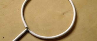
Loop antenna
Directivity - bilobe
Used to receive UHF TV programs.
As a variation - a loop antenna with a reflector:
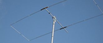
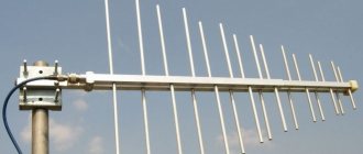
Log-periodic antenna
The gain properties of most antennas vary greatly with wavelength.
One of the antennas with a constant radiation pattern at different frequencies is the LPA. The ratio of maximum to minimum wavelength for such antennas exceeds 10 - this is a fairly high ratio. This effect is achieved by using vibrators of different lengths mounted on parallel carriers. The radiation pattern is as follows:
It is actively used in cellular communications during the construction of repeaters, using the ability of antennas to receive signals in several frequency ranges at once: 900, 1800 and 2100 MHz.
Polarization
Polarization
is the direction of the vector of the electrical component of an electromagnetic wave in space. There are: vertical, horizontal and circular polarization.
Polarization depends on the type of antenna and its location. For example, a vertically located asymmetrical vibrator gives vertical polarization, and a horizontally located one gives horizontal polarization.
Horizontal polarized antennas give a greater effect, because... natural and industrial interference have mainly vertical polarization. Horizontally polarized waves are reflected from obstacles less intensely than vertically. When vertically polarized waves propagate, the earth's surface absorbs 25% less of their energy.
When passing through the ionosphere, the plane of polarization rotates; as a result, the polarization vector on the receiving side does not coincide and the efficiency of the receiving part decreases. To solve the problem, circular polarization is used.
All of these factors should be taken into account when designing radio links for maximum efficiency.
PS:
This article outlines only a small part of the antennas and does not pretend to replace the textbook on antenna-feeder devices.
Antenna assembly
Let's remove the insulation from a piece of wire one meter long.
I got a wire with a diameter of 4.5mm
The tools you will need are a vice and a hammer. Measure approximately 11cm each and bend at an angle of 90°
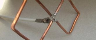
The end result is to get such a “geometric” figure
We cut off the excess and solder the ends. It should look something like this...
Solder the cable as shown in the photo.
We lay the cable along one side of the square and secure it with clamps. This arrangement of the cable is necessary for its coordination (there are different opinions, not everyone agrees with this statement).
When using a reflector, the antenna sheet at the extreme points of the squares can also be secured using metal stands, for example, soldered onto the remains of the same copper wire - there are points with zero potential (highlighted in green). In other places, fastening is allowed only through a dielectric.
Three-element antenna Wave Channel
Two-element “Wave Channel” antennas are rarely used, since their characteristics are not much better than those of a single vibrator. Therefore, consider a three-element antenna, which is shown in Fig. 1. The antenna elements are made of a metal tube with a diameter of 12-20 mm.
Rice. 1. Three-element antenna “Wave channel”.
The mast and boom can be metal. In this case, the antenna elements must be reliably electrically connected to the boom by soldering or welding. If the boom is made of insulating material, there is no need to specially connect the antenna elements together. The location of the antenna elements corresponds to the horizontal polarization of the signal.
Tests
And finally, a performance check and a rough
assessment of the quality of the resulting antenna.
In fact, everything is simple with the test - turn it on, it works! And to evaluate whether the game was “worth the candle,” let’s compare the parameters of the received signal from the manufactured antenna with the one I’m already using at the dacha, with a declared gain of 11dBi
The antenna is installed in the attic of a country house, at a distance of approximately 16 km from the tower.
Signal level: factory stationary antenna on the left / homemade on the right
At first glance, the difference is only 1% (95 versus 94) - but this is not a completely correct comparison, since my external antenna is connected through a splitter, which further weakens the signal.
How a digital antenna for a TV works: I’ll explain it simply
Before you start assembling any of the four models of receiving antennas, you should have a good understanding of the processes that should take place in them.
Electromagnetic waves propagate in all directions of the horizon from the electrical signal transmitter generator installed on the television tower.
They have sufficient power for their coverage area, but their signal weakens as distance increases. Its magnitude is also affected by the terrain, various electrical and magnetic obstacles, and the state of the atmosphere.
In a vibrator oriented perpendicular to the movement of the electromagnetic wave, voltage is induced according to the laws of induction. The positive and negative half-waves of the harmonic create their own sign.
The voltage reaches its maximum value - amplitude at points of time corresponding to ¼ and ¾ of the period or 90 and 270 degrees from the sinusoid of electromagnetic wave intensity.
Any shape and size of active vibrators are created for the most effective voltage induction with minimal energy loss. The position of these points is calculated using the wavelength or harmonic frequency.
The voltage, closed to the internal resistance of the television receiver, generates an electric current in the created circuit. Its shape and direction change and proportionally repeat the signals of the transmitter on the active load.
Due to the use of various types of digital modulation on the transmitter side, information signals are received and processed within the television receiver circuit.
I will not go further into considering the question of how a digital antenna for a TV works during its creation.
What technical characteristics of the antenna determine the quality of TV signal reception?
The antenna is classified as a reversible device because it works the same on the transmitter and receiver sides. When analyzing the characteristics, its inclusion is used as a generator.
To effectively receive a digital signal, it is necessary to take into account that on the generator side, the emitter of electromagnetic waves can be positioned at any angle to the horizon, but only two directions are legally accepted: horizontal and vertical.
Our task is to repeat this orientation for our own TV.
The direction of polarization and other digital signal transmission data can be found on the operator’s website through a search engine.
We go to the website and select the required information.
We are primarily interested in 3 characteristics:
- channel number and its frequency, for which we will create an antenna according to strict dimensions;
- the radius of the transmitter service area, which affects the signal quality and the choice of vibrator design;
- direction of polarization.
The distance the TV is located from the transmitting tower greatly affects the design of the antenna.
The higher the antenna is installed, the better the quality of the received signal, but the length of the cable can weaken it significantly . In this regard, residents of the upper floors of multi-story buildings have a significant advantage over their neighbors below.
For a reliable reception zone, I tested the simplest Kharchenko models and loop assemblies made of coaxial cable and wire, which have a wide range of reception frequencies.
For long distances it is better to assemble a wave channel or a log-periodic circuit. Of the simple designs, the Turkin antenna, modified by Polyakov, has proven itself well.
For example, in my area the distance from the TV tower was 25 km, which is within the zone of reliable reception, and the signal frequency is 626 MHz of vertical polarization.
I calculate the length of the electromagnetic wave through the speed of light by frequency: λ=300/626=0.48 meters. The half wave will be 24 cm, and the quarter wave will be 12.
Based on these characteristics, I made 4 test antennas for digital television with my own hands, which I describe below.
Assessing the performance of the antenna
Let's try to make a more correct comparison by connecting through the splitter input.
Well, in addition, for clarity, let’s add the number of participants List of antennas taking part in the comparison:
1. External antenna Funke BM 4551 external long-range,
declared gain, from some sources (bought at Yulmart), up to 16dB
2. There is an old UHF loop antenna, from TV Electronica 313d, I must say, despite its simplicity, it’s a very good antenna, that’s why it’s been preserved
3. I went to the store and bought for comparison in the review one of the cheapest, such as a symmetrical vibrator (100% the most purchased by pensioners, due to the low price).
I will carry out all “measurements” at one point, located as close as possible to the external antenna - its location was experimentally selected based on the maximum signal, so we can say that the conditions are approximately the same
So, we have already seen the signal level from the external antenna at 95% (at the time of current measurements it showed 94%), we take it as a standard. All comparisons are made by connecting antennas to the input on the splitter, to which an external antenna is usually connected.
Loop antenna, from Electronics 82% on 39 multiplex and 66% on 60
Budget with “horns” - 62%/38% (on the verge of losing the broadcast)
Double square - 92% on both multiplexes, about a couple of percent less than the external one
Out of curiosity, I decided to check the work of the reflector, which is easy to make from any metal mesh, plate or even foil... It REALLY works noticeably! The level rose to 96%!, which is even higher than the stationary one, with a declared gain of 11dB.
The most interesting thing is the object that I used as a reflector!
There was no foil in the house; the only thing available with a metal surface of the required size was... a laptop cover (I have a metal case). But the main thing is the result! It’s clear that I’m not going to “tie” the laptop to the antenna, and its amplification is enough for me without a reflector
Conclusion:
I can confidently recommend repeating it!
Simple, “cheap and tasty”... One of the simplest, indoor antenna mounts... with ordinary suction cups - if you’re lucky with the direction to the television center
The next antenna "recommended for repetition" is... log periodic
“Crazy hands” were with you. Good luck and good mood to everyone! ☕
How to make an antenna
In addition to the description of the manufacturing process, the advantages and disadvantages of each antenna for digital TV will be described. Not every type of antenna can be quickly made for a TV. This is explained by the complexity of the design and the need for appropriate calculations.
Antenna cable loop
This can always be done if the old antenna has stopped showing.