Author: Alexander Starchenko
These two types of voltage stabilizers are classified as electronic devices. They do not contain any mechanical or electromechanical devices. They are assembled entirely on semiconductor elements and are characterized by noiselessness, high speed of response to voltage changes and reliability. Such stabilizers are widely used in everyday life and in production.
Design and principle of operation of thyristor and triac stabilizers
The main components of these voltage stabilizers are:
- power autotransformer - used to correct the mains voltage;
- electronic control circuit (usually implemented on a microprocessor basis) – controls all functions of the stabilizer in accordance with signals from sensors of network parameters and load power consumption;
- block of switching power semiconductor switches (thyristors or triacs) - used for switching taps of the windings of a power autotransformer;
- network interference filtering devices – suppress pulse and high-frequency interference.
On the body of electronic stabilizers, as a rule, there is an LCD display and LED indicators that display the values of the operating parameters of the device: voltage values at the input and output, power of the connected load.
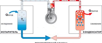
The operating principle of thyristor and triac stabilizers is the same. The input alternating mains voltage is supplied to a converting autotransformer - a type of transformer whose primary and secondary windings are connected, that is, they are not only electromagnetically coupled, but also electrically connected. The secondary voltage is removed from one of several terminals of the autotransformer winding. Connection to each terminal uses a different number of turns of the transformer coil, which will determine the transformation ratio and, accordingly, the output voltage. The most similar operating principle is the relay type of stabilizers.
The parameters of the input and output voltage of the autotransformer are constantly monitored by the microprocessor of the control board. If they deviate from the norm in any direction, the microprocessor sends a control signal to turn on a specific power switching device - a semiconductor switch. Depending on the type of power switches used, a distinction is made between thyristor (using thyristors) and triac (respectively, using triacs) devices.
Types of modern devices
The development of semiconductor technology has made it possible to control power using radioelements with an efficiency of eighty percent. This made it possible to comfortably use them in a network with a voltage of 220 volts, without requiring large cooling systems. And the advent of integrated circuits made it possible to achieve miniature sizes of the entire regulator as a whole.
Currently, production produces the following types of devices:
- Phase. Used to control the brightness of incandescent or halogen lamps. Another name for them is dimmers.
- Thyristor. The operation is based on the use of a delay in switching on a thyristor switch during a half-cycle of alternating current.
- Triac. Power is regulated by changing the number of voltage half-cycles that act on the load.
- Travel regulator. Allows you to smoothly change the electrical power supplied to the electric motor.
In this case, the adjustment occurs regardless of the shape of the input signal. Based on their location, control devices are divided into portable and stationary. They can be carried out either in an independent housing or integrated into the equipment. The main parameters characterizing electrical energy regulators include:
- smooth adjustment;
- operating and peak power input;
- range of input operating signal;
- Efficiency
Thus, a modern electrical power regulator is an electronic circuit, the use of which allows you to control the amount of energy passed through it.
Thyristor control device
The operating principle of such a device is not particularly complicated. Basically, a thyristor converter is used to control low-power devices. A typical circuit of a thyristor power regulator consists directly of the thyristor itself, bipolar transistors and resistors that set their operating point, and a capacitor.
Transistors, operating in switching mode, generate a pulse signal. As soon as the voltage value on the capacitor is compared with the operating voltage, the transistors open. The signal is supplied to the control output of the thyristor, opening it too. The capacitor is discharged and the key is locked. This repeats in a cycle. The longer the delay, the less power goes to the load.
The advantage of this type of regulator is that it does not require adjustment, but the disadvantage is that it generates excessive heat. To combat overheating of the thyristor, an active or passive cooling system is used.
This type of regulator is used to convert power supplied to both household appliances (soldering iron, electric heater, spiral lamp) and industrial ones (soft start of powerful power plants). Switching circuits can be single-phase or three-phase. The most used: ku202n, VT151, 10RIA40M.
Triac power converter
A triac is a semiconductor device intended for use in an alternating current circuit. A distinctive feature of the device is that its terminals are not divided into anode and cathode. Unlike a thyristor, which passes current in only one direction, a triac conducts current in both directions . That is why it is used in AC networks.
An important difference between triac circuits and thyristor circuits is that there is no need for a rectifier device. The principle of operation is based on phase control, that is, on changing the opening moment of the triac relative to the transition of the alternating voltage through zero. This device allows you to control heaters, incandescent lamps, and electric motor speeds. The signal at the output of the triac has a sawtooth shape with a controlled pulse duration.
Independent production of this type of device is easier than thyristor one. Medium power triacs of the following types have gained wide popularity: BT137–600E, MAC97A6, MCR 22−6. The power regulator circuit based on a triac using such elements is characterized by ease of manufacture and no need for configuration.
Phase transformation method
The dimmer itself has a wide range of applications. One option for using it is to adjust the lighting intensity. The electrical circuit of the device is most often implemented on specialized microcontrollers that use a built-in electronic voltage reduction circuit in their operation. Because of this, dimmers are able to smoothly change power, but are sensitive to interference.
Read also: DIY three-phase power regulator
Phase power regulators are not stabilized using zener diodes, but use thyristors operating in pairs as a stabilizer. The basis of their operation lies in changing the opening angle of the key thyristor, as a result of which the load receives signals with the initial part of the half-cycle cut off, reducing the effective voltage value. The disadvantages of dimmers include high ripple factor and low power factor of the output signal.
When dimmers operate in a wide range of frequencies, electromagnetic interference is generated. Such radiation leads to a decrease in efficiency due to the appearance of parasitic current in the conductors. To combat such currents, inductive-capacitive filters are added to the design.
Thyristors and triacs. What is the difference?
Thyristors and triacs are semiconductor elements, the control of which (changing their switching state) is carried out by applying a positive potential to the control electrode. Their difference lies in the number of layers with different conductivities in the element plate.
The thyristor is a unidirectional AC converter. In its structure, the element has a control electrode, an anode and a cathode.
A triac is two back-to-back thyristors that are located parallel to each other. In a triac, each electrode is an anode and a cathode at the same time, due to which this semiconductor switch is capable of conducting current in two directions.
Next, we will consider the features and differences of devices with switching implemented on thyristor and triac switches.
Do-it-yourself 220 V stabilizer circuit for home
Triac-type stabilizers function similarly to relay devices, and the significant difference is the presence of an element responsible for switching the transformer winding. The relay in this case is replaced by powerful triacs, which are controlled by controllers.
Winding control of triacs is non-contact, with no characteristic sound signals in the form of fairly loud clicks. Winding an automatic transformer involves the use of copper wire.
Voltage stabilizer circuit
The main components and tools required for self-assembly of the stabilizer are presented:
- power supply;
- a rectifier that measures the voltage amplitude;
- comparator;
- controller;
- amplification devices;
- light diodes;
- a unit for braking the load connection;
- automatic transformer;
- keys;
- fuse switch;
- household soldering iron and tweezers.
A standard printed circuit board measuring 11.5x9.0 cm is made using traditional foil-type fiberglass laminate, after which the layout of the elements printed on a laser MFP is transferred using an iron.
- magnetic circuit with a cross section of 187 mmVI;
- PEV-2 cable in the amount of three pieces for a winding with a number of turns of 8669 and a pair of windings with 522 turns.
At the final stage of assembling the voltage stabilizer, flashing light diodes are installed on the board.
Independent implementation of the simplest 220 V stabilizer involves connecting a non-electronic transformer to obtain output values that are approximately 11% higher than the standard mains voltage.
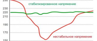
Operation scheme, strengths and weaknesses of thyristor stabilizers
Let's take a closer look at the operating algorithm of the thyristor stabilizer:
- When changing the input current parameters, a delay phase (up to 20 ms) is used to measure the value of the input network voltage.
- Having compared the actual and permissible current characteristics, if necessary, the control board processor issues a command to correct the output voltage:
- in cases where input voltage deviations are within the permissible range, it is corrected to the required value;
- In case of voltage surges outside the permissible range, the protection system ensures emergency shutdown of the device.
Thyristor voltage stabilizers have the following advantages:
- relatively high performance – 20 ms (compared to relay devices);
- high efficiency, which is achieved due to the absence of relays and moving elements;
- ability to function in an external environment with high or low temperatures;
- durability and reliability due to the absence of mechanical parts;
- silent operation;
- overload resistance.
Thyristor devices are also distinguished by a fairly high accuracy of output voltage stabilization (from 5 to 10%) compared to relay models, as well as a relatively wide input voltage range, which allows them to be used in networks with extremely low-quality voltage.
A serious disadvantage of thyristor stabilizers is the discreteness (steps) of voltage correction. Stepped voltage surges that appear when switching transformer windings impair the accuracy of stabilization and reduce the operating speed of the device.
Due to these disadvantages, thyristor stabilizers cannot be used to power loads that are particularly sensitive to voltage changes (for example, PCs and peripheral devices, professional audio and video devices, as well as electronically controlled devices).
In addition, the output voltage of thyristor stabilizers has a shape other than sinusoidal (trapezoidal or with other distortions, depending on the specific model), which makes their use undesirable to power loads with electric motors (for example, pumps, heating systems).
Design characteristics
Compared to analogues, stabilizers of this type have the following design features:
- High-speed semiconductor parts such as triacs are used as power switches in this device;
- To obtain a stable output potential difference, stabilizers of this type use a built-in autotransformer with windings connected in series;
- The operation of the device is controlled by an electronic controller - a special board with a microcircuit placed on it.
Triac
Scheme of operation, advantages and disadvantages of triac stabilizers
Triac voltage stabilizers have an operating principle similar to thyristor devices.
Their obvious advantages, of course, include the above-listed advantages that distinguish thyristor devices:
- speed and accuracy of voltage regulation;
- high efficiency value;
- silent operation (which is especially important when installed in residential areas);
- long-term service life;
- reliability of operation due to the complete absence of mechanical moving parts.
Modern triac voltage stabilizers, like their thyristor analogues, are distinguished by a wide input voltage range and the ability to operate at fairly low temperatures.
Their significant disadvantages are their high cost compared to relay models and stepwise regulation of the output voltage. The disadvantages also include the greater bulkiness of power switches compared to thyristor analogues: one triac occupies an area sufficient to accommodate several thyristors. Of course, this does not have a positive effect on the overall dimensions and weight of the devices.
Comparing the types of semiconductor switches used, we add that triacs are less resistant to current overloads and during operation can heat up much more, which increases the risk of their failure.
Triac stabilizers have the same application restrictions as thyristor ones. They cannot be called a good solution for organizing the protection of electric motors or loads with an electric drive due to the distortion of the output signal shape: as a rule, this is a modified sine wave. Speaking about limitations in use, it is worth adding their low resistance when working with an inductive load.
Attention!
When purchasing a triac stabilizer to power voltage-sensitive electrical devices, it is necessary to clarify the number of power semiconductor switches involved in the stabilizer circuit - the more there are, the more the device will be able to provide an output voltage closer to the rated value.
Powerful electronic stabilizer
One of the leaders in the production of energy systems is, it uses innovative technologies in its developments, which makes it possible to minimize some of the disadvantages of thyristor voltage stabilizers.
The single-phase thyristor stabilizer “Energy Classic 12,000” is a modern and reliable device with high parameters. The device operates in the input voltage range from 125 to 254 volts. The maximum permissible values can be 60 volts at a minimum and 265 volts at a maximum. The stabilizer has a 12-stage switching circuit made using powerful thyristors. Switching time does not exceed 20 ms.
This and a large number of other thyristor stabilizers are presented on the website of the official partner of the Energia company - VoltMarket.ru.
If you want to purchase a triac stabilizer, then look at the options on the company’s website at this link.
The stabilizer has protection against undervoltage, overvoltage and overload. When the temperature of the power transformer exceeds 120°C, the protection is also triggered and the stabilizer is turned off. Permissible short-term overload up to 180%, can be 0.3 seconds. The input filter suppresses all types of high-frequency and impulse noise. When powering a load with normal mains voltage, a bypass system is used. This stabilizer from Energia is designed for operation in a heated room with a humidity level of no more than 80%.
With this they read:
Selecting a battery for a UPS: characteristics, features and types of batteries
Voltage stabilizers for the home: reviews, which one is better and what criteria to use to make a choice
How to choose a three-phase voltage stabilizer?
Which voltage stabilizer is better: main types and their features
Did you like the article? Share with friends on social networks!
- Sergey
08/02/2017 at 18:42Hello! As I understand it, thyristor and triac stabilizers are better than relay ones. But there are some kind of Inverter (double conversion) stabilizers. Therefore, the question arose: Are inverter stabilizers the same as thyristor and triac stabilizers or is it a different technology? Thank you!
Reply ↓
Alexander Starchenko
(Post author)08/05/2017 at 17:43
Hello, Sergey. Each has its own advantages and disadvantages, for example, thyristor and triac stabilizers cannot be used with equipment that has an electric motor in its structure, since they do not produce a pure sine wave. Inverter stabilizers have a significant difference from this type of stabilizer; they do not have an autotransformer in their structure. They are also distinguished by their higher cost, ideal sine wave output, and the ability to operate at low temperatures. Read more about inverters here. I also advise you to read the article about the differences between types of stabilizers at this link.
07/24/2018 at 21:14
Good afternoon At the entrance to my country house there are 3 phases. There are no three-phase consumers. Question: can I hang a stabilizer (and what type?) on only one phase, or in the case of 3 phases, do I need to hang stabilizers on each? I don’t consider a three-phase stub, because equipment important for protection hangs on one phase.
Reply ↓
- Alexander Starchenko
(Post author)08/07/2018 at 05:39
Good afternoon. What will be the type and power of the load? For demanding consumers, for example, RUCELF BOILER-600 is well suited. It has a sinusoidal voltage for sensitive electronics, power up to 600VA (about 300W recommended). Its cost is 3500 rub. Delivery throughout Russia 500 rub. If interested, call the phone number listed on the website.
08/01/2018 at 21:43
Hello! I purchased a relay stabilizer on the Internet. In principle, not a bad thing, but with the help of a measuring device I saw that in XX mode it consumes about 1.6 - 1.7 A !!! What an appetite!.. Why is there no such important point as current xx in the descriptions / characteristics / of stabilizers??? Commercial ploy? Now my stab. hanging on the wall in bypass mode as a pile of metal a la “suitcase without a handle”... Are there really no stubs with “divine” current xx?!. Thank you and good luck!
Reply ↓
- Igor
03/03/2020 at 20:58
See efficiency parameter. Usually 95-97%. 3% of the power of 8 kW is 240 W or 240 V * a / 220 V = 1.1 A
08/20/2018 at 21:58
Good day. Tell me, is it possible to use the IEK-2000 seven-voltage stabilizer to power an inverter-type air conditioner and a TV? And then they write that there is no sinusoid at the output, and it is harmful for the motor, etc. So, is it possible to use it or look for it with a servo drive? I don’t want a relay because of the clicking of the relay.
Reply ↓
- Alexander Starchenko
(Post author)08/28/2018 at 06:34
Good day, Sergey. That's right, it's very harmful for the motor, the brushes will burn out. But the servo will also make noise - the motor will hum. The relay will not click much at low power.
02.12.2018 at 12:24
The person writes that the air conditioner is an INVERTER type, that is, it has no limitation on the shape of a sinusoid at the input.
Let's sum it up
Comparing triac and thyristor voltage stabilizers with each other and with other types of devices, we can come to the following conclusions:
- both types of devices have both similar capabilities for voltage stabilization and almost identical disadvantages, one of which is stepwise adjustment and, as a consequence, a non-sinusoidal shape of the output signal;
- these stabilizers cannot protect equipment sensitive to network quality, as well as devices with electric motors;
- both devices are not much superior to relay voltage stabilizers in their operating parameters, but their cost is much higher;
- If thyristor and triac devices break down, repairing their electronic components will cost more than previous generations of voltage stabilizers operating on a similar principle.
Practical examples for review
The most popular among radio amateurs are circuits designed to control the brightness of a lamp and change the power of a soldering iron. Such circuits are easy to repeat and can be assembled without the use of printed circuit boards by simple overhead mounting.
Circuits made independently are in no way inferior in performance to factory ones, since they do not require settings and, with working radio components, are immediately ready for use. If you are unable or want to make the device yourself from scratch, you can purchase kits for self-production. Such kits contain all the necessary radio elements, a printed circuit board and a circuit with assembly instructions.
Dominant scheme
The easiest way to assemble such a device is with a thyristor. The operation of the circuit is based on the ability of the thyristor to open when the input sinusoid passes through zero, as a result of which the signal is cut off and the voltage across the load changes.
The circuit for replicating the thyristor power regulator is based on the use of thyristor VS1, which is used as KU202N. This radio element is made of silicon and has a pnp type structure. Used as a symmetrical switch for medium power signals and switching AC power circuits.
When a voltage of 220V is applied, the input signal is rectified and sent to capacitor C1. As soon as the voltage drop across C1 is equal to the potential difference, at the point between resistances R3 and R4, bipolar transistors VT1 and VT2 open. The voltage level is limited by the zener diode VD1. The signal is sent to the control terminal of KU202N, and capacitor C1 is discharged. When a signal occurs at the control terminal, the thyristor is unlocked. As soon as the capacitor is discharged, VT1 and VT2 close, and the thyristor also closes accordingly. At the next half-cycle of the input signal, everything repeats again.
KT814 and KT815 are used as transistors. The discharge time is adjusted using R5 and the power too. Zener diode is used with a stabilization voltage from 7 to 14 volts.
Such a regulator can be used not only as a dimmer, but also to control the power of a commutator motor. The dominant circuit can operate at currents up to 10 amperes; this value directly depends on the characteristics of the thyristor used, and it must be installed on the radiator.
Soldering iron heating controller
Controlling the power of a soldering iron not only has a positive effect on its service life, preventing the tip and its internal elements from overheating, but also allows you to solder radioelements that are critical to the temperature of the device.
Devices for monitoring the temperature of a soldering iron have been produced for a long time. One of its types was a domestic device, produced under the name “Additional device for an electric soldering iron type P223.” It allowed connecting a low-voltage soldering iron to a 220V network.
The easiest way to make a regulator for a soldering iron is using a triac KU208G.
Power contacts are connected in series to the load. Therefore, the current flowing through the triac coincides with the load current. To control the key mode, dinistor VS2 is used. Capacitor C1 is charged through resistors: R1 and R2. Operation indication is organized using VD1 and LED. Because it takes time for the voltage across the capacitor to change, a phase shift occurs between the mains voltage and the capacitor voltage. By changing the value of resistance R2, the magnitude of the phase shift is adjusted. The longer the capacitor is charged, the less the triac is in the open state, and therefore the power value is lower.
This regulator is designed to connect a load with a power of up to 300 watts. When using a soldering iron with a power of more than 100 watts, the triac should be installed on a radiator. The manufactured board easily fits on a PCB measuring 25x30 mm and is freely placed in an internal power socket.
Inverter stabilizers as an alternative to thyristor and triac ones
Despite the fact that triac and thyristor stabilizers are still quite popular, they are gradually but surely being forced out of the market by a new type of device - inverter voltage stabilizers. These devices were developed in 2015 and are rightfully considered products of a new generation.
Inverter models, unlike triac and thyristor models, operate on a completely different principle. The circuit of their operation does not include an autotransformer or any switching elements. Voltage correction is performed using a rectifier, capacitor and inverter. First, the input alternating voltage is transformed into direct voltage, and then again into alternating voltage, but already having reference characteristics. Thanks to double conversion technology, these devices can:
- instantly respond to network deviations in the range of 90-310 V;
- stabilize voltage with high accuracy (2%);
- supply a voltage of an ideal sinusoidal shape to the load;
- uninterruptedly power electrical appliances during short-term network outages (up to 200 ms).
The high technical characteristics of inverter stabilizers allow them to be used for the most demanding consumers in terms of power quality in networks with significant voltage fluctuations.
Currently, the Russian manufacturer of power supply systems "Shtil" offers the following models of inverter voltage stabilizers:
- single-phase devices for wall and floor/rack installation with an output power of 0.35-20 kVA;
- 3-in-1 configuration models of floor/rack installation with an output power of 6-20 kVA, designed to operate in a three-phase network to power a single-phase load;
- three-phase floor/rack mounted devices with an output power of 6-20 kVA.
Principle of operation
Digital voltage stabilizer
Such a stabilizing device works as follows:
- The voltage supplied to the device from the external network is measured by the control board (controller) using a special sensor;
- Based on the measurements obtained, the controller makes a decision to adjust the voltage;
- The controller sends the corresponding signal to the input triacs;
- Using the signal sent to the triacs by the controller, a voltage equalized to a certain value is supplied;
- Using an autotransformer located in the housing, the voltage supplied from the external network is equalized to the value necessary for the normal operation of electrical appliances.
This multi-step process takes a fraction of seconds. At the same time, unlike relay models, the presence of triacs makes it possible to turn on and off the transformer windings silently and very quickly.