Electrical machines › DC electric machines
During operation of the DC generator, an emf Ea is induced in the armature winding. When a load is connected to a generator, a current arises in the armature circuit, and a voltage is established at the generator terminals, determined by the voltage equation for the generator armature circuit:
. (28.1)
Here
(28.2)
the sum of the resistances of all sections of the armature circuit: the armature winding ra, the winding of the additional poles rD, the compensation winding rc.o., the series excitation winding and the transition brush contact rsh.
If the machine does not have any of the indicated windings, (28.2) does not include the corresponding terms.
The generator armature is rotated by a drive motor, which creates a torque M1 on the generator shaft. If there is no load connected to the generator (operating in idle mode Ia = 0), then a relatively small idle torque M0 is needed to rotate its armature. This moment is due to the braking moments that arise in the generator when it operates in idle mode: moments from friction forces and eddy currents in the armature.
When the generator operates with a connected load, a current appears in the wires of the armature winding, which, interacting with the magnetic excitation field, creates an electromagnetic torque M
.
In the generator, this moment is directed counter to the torque of the PD
(Fig. 28.1), i.e. it is load (braking).
Rice. 28.1. Torques acting in a DC generator
At a constant rotation speed n = const, the torque of the drive motor M1 is balanced by the sum of counteracting moments: torque x.x. M0 and electromagnetic moment M,
i.e.
. (28.3)
Expression (28.3) is called the torque equation for a generator at a constant load frequency. Multiplying the terms of equation (28.3) by the angular velocity of rotation of the armature ω , we obtain the power equation:
,
(28.4)
where P1 = M1 ω
— power supplied from the drive motor to the generator (mechanical); P0 = M0ω no load power, i.e. power supplied to the generator in no mode. (with the load off); PEM = Mω—electromagnetic power of the generator.
According to (25.27), we get
,
or taking into account (28.1)
, (28.5)
where P2
— useful power of the generator (electric), i.e. the power supplied by the generator to the load;
Pеa
is the power loss due to heating of the windings and brush contact in the armature circuit.
Taking into account the excitation losses of the REV generator, we obtain the power equation for the DC generator:
. (28.6)
Therefore, the mechanical power developed by the drive motor P1
,
is converted in the generator into useful electrical power P2
transferred
to the load, and power
.
Since generators usually operate at a constant speed, their characteristics are considered under the condition n = const.
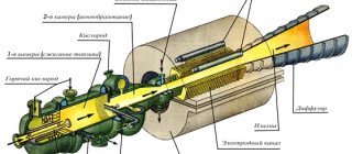
Generator design
Let's look at what a DC generator is. Firstly, this is the device body made of durable steel or cast iron. The magnetic field created by the poles of the generator also passes through the body. Secondly, these are the rotor and stator.
An excitation coil is attached to the ferromagnetic stator. The direction of the magnetic flux is determined by the stator cores equipped with poles.
For high efficiency of the generator itself, the rotor is assembled from metal plates. In addition, this rotor design can significantly reduce the occurrence of eddy currents.
A copper or copper-plated winding is wound onto the metal plates of the core - a self-excitation winding. The number of generator brushes made of graphite depends on the number of poles on it, at least two. We can clearly see the design of the generator in the figure.
The output of the generator circuit is connected using collector plates. The plates are made from an affordable and good conductor of electric current - copper, and are separated from each other by a dielectric.
Energy diagram
The energy diagram of the independent excitation generator is presented in Figure 2. The mechanical power P1 received from the primary engine, minus the losses of mechanical pmx, magnetic pmg and additional pm, is converted in the armature into electromagnetic power Pem. The power PEM is partially spent on electrical losses of the relay in the armature circuit (in the windings of the armature, additional poles and compensation windings and in the transition resistance of the brush contact), and the rest of this power represents the useful power P2 given to consumers. Excitation losses pv in the independent excitation generator are covered by an external current source.
Based on what is stated for the independent excitation generator, we have the power equation
| P2 = P1 – pmx – pmg – pd – rela = Pem – rela | (1) |
You can also write the following power equation:
| P1 = pmx + pmg + pd + Pem | (2) |
Similar energy diagrams can be constructed for other types of generators.
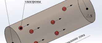
Operating principle
The principle of operation of a direct current generator, like any other device of a similar type, is based on the phenomenon of electromagnetic induction, familiar to us from school, and the appearance of electromotive force in the device - EMF. Let's remember school physics: if you attach any load to a conductor with a permanent magnet rotating inside it, then an alternating current will appear in it. This is possible due to the fact that the magnetic poles of the magnet itself have swapped places.
To obtain a constant current, it is necessary to connect the load connection points synchronously with the rotation speed of the magnet. This is what the generator's commutator is designed for, mounted on the rotor and rotating at the same frequency.
The energy obtained as a result of this entire process is removed using graphite brushes, which have good conductivity and fairly low friction. When the collector plates are switched, the EMF is zero, but its polarity does not change due to reconnection to another conductor.
Setting the brushes to neutral
Typically the brushes are installed at geometric neutral.
The brushes are set to neutral using the inductive method - by turning on and off the direct current in the excitation winding of a stationary machine and observing the readings of a voltmeter or galvanometer connected to the brushes. The brush traverse is installed and secured in a position in which the deflection of the device needle when turning the excitation current on and off is zero or minimal. It is better to have a device with a zero in the middle of the scale. The current in the field winding should not exceed approximately 10% of the rated current to avoid inducing large em. d.s. self-induction that can damage the insulation of the field winding.
You can also install the brushes in a position where, when the generator is idling, the voltage is maximum or the engine speed is minimum. However, this method is more crude.
Source: Woldek A.I., “Electrical machines. Textbook for technical schools" - 3rd edition, revised - Leningrad: Energy, 1978 - 832 p.
Classification
Generators are divided into classes based on the principle of how they are excited. There are two main types of classification of generators: self-excited and independently excited generators.
The first class is devices where the winding is powered directly from the armature. It can be divided into sequential, parallel and mixed excitation. The second class is divided into electromagnetic and magnetoelectric excitation.
To main
§ 111. Methods of exciting DC generators
Depending on the method of powering the excitation winding, modern DC generators use independent magnetic flux excitation and self-excitation. With independent excitation (Fig. 154, a), the excitation winding is connected to an auxiliary source of direct current energy. To regulate the excitation current I
in the winding circuit resistance
r
p is switched on.
With such excitation, the current Iv
does not depend on the current in the armature
Ii
.
The disadvantage of independent excitation generators is the need for an additional energy source. Despite the fact that this source usually has low power (several percent of the power of generators), the need for it is a great inconvenience and therefore independent excitation generators find limited use in special installations (HD) and in high-voltage machines in which the excitation winding is powered from armature chains are unacceptable for design reasons. Self-excited generators have wider applications. Depending on the connection of the excitation winding, they can be parallel (Fig. 154, b), sequential (Fig. 154, c) and mixed (Fig. 154, d) excitation. For parallel excitation generators, the current I
is small (several percent of the rated armature current), and the field winding has a large number of turns.
With series excitation, the excitation current is the armature current and the excitation winding has a small number of turns. With mixed excitation, two excitation windings are placed at the poles of the generator - parallel and serial. The process of self-excitation of DC generators proceeds the same way for any excitation scheme. Let us consider the process of self-excitation of a parallel excitation generator, which has received the most widespread use. Some prime mover rotates the armature of the generator, in the magnetic circuit (yoke and pole cores) of which a small residual magnetic flux Φrest is preserved. This magnetic flux is induced in the winding of the rotating armature. d.s. E
rest, which is a few percent of the rated voltage of the machine.
Under the influence of e. d.s. E
ost in a closed circuit consisting of an armature and an excitation winding, a current
I
century flows.
The magnetizing force of the field winding I
вωв (ωв is the number of turns) is directed in accordance with the flow of residual magnetism, increasing the magnetic flux of the machine Φ
m
, which causes an increase in both e.
d.s. in the armature winding E
, and the current in the field winding
I
.
An increase in the latter causes a further increase in Φ m
, which in turn increases
E
and
I
in.
Due to the saturation of the steel of the magnetic circuit of the machine, self-excitation does not occur indefinitely, but up to a certain voltage, depending on the speed of rotation of the machine’s armature and the resistance of the field winding circuit. When the steel of the magnetic circuit is saturated, the increase in magnetic flux slows down and the self-excitation process ends. An increase in resistance in the field winding circuit reduces both the current in it and the magnetic flux excited by this current. Therefore, e decreases. d.s. and the voltage to which the generator is excited. A change in the rotation speed of the generator armature causes a change in e. d.s., which is proportional to the speed, as a result of which the voltage to which the generator is excited also changes. Self-excitation of the generator occurs only under certain conditions, which boil down to the following. 1. The presence of a flow of residual magnetism. In the absence of this flow, no e is created. d.s. E
ost, under the influence of which current begins to flow in the excitation winding, so that excitation of the generator will be impossible.
If the machine is demagnetized and has no residual magnetization, then a direct current from some foreign source of electrical energy must be passed through the excitation winding. After disconnecting the field winding, a residual magnetic flux will remain in the machine. 2. The field winding must be connected so that the magnetizing force of this winding increases the flux of residual magnetism. When the field winding is switched on oppositely, its magnetizing force will reduce the residual magnetic flux and, during prolonged operation, can completely demagnetize the machine. In this case, it is necessary to change the direction of the current in the excitation winding, i.e., swap the wires suitable for its terminals. 3. The resistance of the field winding circuit should not be excessively large; with a very high resistance of the excitation circuit, self-excitation of the generator is impossible. 4. The resistance of the external load should be relatively high, since with low resistance the excitation current will also be small and self-excitation will not occur. Previous page
| table of contents | Next page |
Photos of DC generators
1+
Read here! What is an ATS for a generator?