What is a pulse counter?
A pulse counter is a serial digital device that stores a word of information and performs a counting micro-operation on it, which consists of changing the value of a number in the counter to 1. Essentially, the counter is a set of triggers connected in a certain way. The main parameter of the counter is the counting module. This is the maximum number of single signals that can be counted by the counter. Counters are designated by ST (from the English counter).
Summing pulse counter
Let's consider a summing counter (Fig. 3.67, a). Such a counter is built on four JK flip-flops, which, if there is a logical signal “1” at both inputs, switch when negative voltage drops appear at the synchronization inputs.
Timing diagrams illustrating the operation of the counter are shown in Fig. 3.67, b. Xi denotes the counting module (pulse counting coefficient). The state of the left trigger corresponds to the least significant digit of the binary number, and the right one corresponds to the most significant digit.
In the initial state, all flip-flops are set to logical zeros. Each trigger changes its state only at the moment when it is affected by a negative voltage drop.
Thus, this counter implements the summation of input pulses. From the timing diagrams it can be seen that the frequency of each subsequent pulse is two times less than the previous one, that is, each trigger divides the frequency of the input signal by two, which is used in frequency dividers.
How are they classified?
It should be noted that the selection can be based on many features. Therefore, there is a very detailed classification of pulse counters:
- By the number of stable states in which a trigger can exist:
- binary;
- ternary;
- n-ichny.
- Depending on the counting module:
- binary;
- using a variable counting module;
- BCD;
- using an arbitrary constant module.
- Depending on the direction of the account:
- subtractive;
- summative;
- reversible.
- Depending on the specifics of creating internal connections:
- accelerated: i. parallel;
- ii. end-to-end.
- sequential;
- combined;
- ring.
- Depending on how the trigger switches:
- synchronous;
- asynchronous.
- And the Johnson counter is highlighted separately.
And so that you can better understand the operating features of these mechanisms, we suggest that you familiarize yourself with several representatives that will be discussed further.
Three-bit subtractor counter with serial carry
Let's consider a three-bit subtracting counter with sequential carry, the circuit and timing diagrams of which are shown in Fig. 3.68.
Vasiliev Dmitry Petrovich
Professor of Electrical Engineering, St. Petersburg State Polytechnic University
Ask a Question
The counter uses three JK flip-flops, each of which operates in T-flip-flop (flip-flop with counting input) mode.
Logic 1s are applied to the inputs J and K of each flip-flop, therefore, upon the arrival of the falling edge of the pulse supplied to its synchronization input C, each flip-flop changes the previous state. Initially, the signals at the outputs of all flip-flops are equal to 1. This corresponds to storing the binary number 111 or the decimal number 7 in the counter. After the end of the first pulse F, the first flip-flop changes state: the signal Q1 becomes equal to 0, and ¯Q1 − 1.
Vasiliev Dmitry Petrovich
Professor of Electrical Engineering, St. Petersburg State Polytechnic University
Ask a Question
The remaining triggers do not change their state. After the end of the second synchronization pulse, the first trigger changes its state again, moving to state 1 (Qx = 0). This ensures a change in the state of the second trigger (the second trigger changes state with some delay relative to the end of the second synchronization pulse, since its overturning requires time corresponding to the time of operation of itself and the first trigger).
After the first pulse F, the counter stores the state 11O. Further changes in the counter state occur in the same way as described above. After state 000, the counter goes back to state 111.
What are devices powered by?
Different types of pulse counters can be powered by different voltages, mainly:
- alternating or direct electricity ranging from 18.0 to 36.0 volts;
- alternating or direct electricity ranging from 85.0 to 240.0 volts.
Signals arriving at the input of devices can have amplitudes within the same limits as the supply voltage.
Regarding the output contact of the meter, the voltage on it can reach up to 250.0 volts with a current of up to 3.0 amperes. This does not apply to high-speed counters. Their output is an electronic switch assembled using transistor logic.
Three-digit self-stopping subtracting counter with serial carry
Consider a three-bit self-stopping subtractive counter with sequential carry (Fig. 3.69).
After the counter transitions to state 000, a logical 0 signal appears at the outputs of all flip-flops, which is fed through an OR logic element to the inputs J and K of the first flip-flop, after which this flip-flop exits the T-flip-flop mode and stops responding to F pulses.
Setting the readings
To enter a counting setting on a typical pulse counter, you must perform the following steps:
- turn on the “enter” button - the device will go into the state of flashing the smallest digit of the setting;
- select the desired number value;
- move to the next discharge position using the “select” button;
- thus setting the values of each position to reach the highest rank.
Three-bit up/down counter with serial carry
Consider a three-bit up/down counter with sequential carry (Fig. 3.70).
In subtraction mode, the input signals must be applied to the TV input. In this case, a logical 0 signal is supplied to the Tc input. Let all flip-flops be in state 111. When the first signal arrives at the Tv input, a logical 1 appears at the T input of the first flip-flop, and it changes its state. After this, a logical 1 signal appears at its inverse input.
When the second pulse arrives at the TV input, a logical 1 will appear at the input of the second trigger, so the second trigger will change its state (the first trigger will also change its state upon the arrival of the second pulse). Further changes in state occur in a similar way. In addition mode, the counter operates similarly to a 4-bit adding counter. In this case, the signal is supplied to the Tc input. A logical 0 is supplied to the TV input. As an example, let’s consider up/down counter microcircuits (Fig: 3.71) with parallel transfer of the 155 series (TTL):
- IE6 - binary decimal up/down counter;
- IE7 is a binary up/down counter.
The counting direction is determined by which pin (5 or 4) the pulses are sent to. Inputs 1, 9, 10, 15 are informational, and input 11 is used for pre-recording. These 5 inputs allow pre-recording to the counter (preset). To do this, you need to submit the appropriate data to the information inputs, and then apply a low-level write pulse to input 11, and the counter will remember the number.
Input 14 is the O setting input when a high voltage level is applied. To build counters of larger capacity, forward and reverse transfer outputs are used (pins 12 and 13, respectively). From pin 12 the signal should be fed to the forward counting input of the next stage, and from pin 13 to the downward counting input.
Electricity meters. Part 1. Induction and electronic
In the modern world, you can no longer do without these devices.
After all, everyone in their house has electrical wiring, therefore, there must be an electric meter. But here's the problem. As soon as the time comes to replace or install a meter, we go to the store and are bombarded with a barrage of choices. We start to get lost and end up choosing the wrong thing.
To prevent this from happening, let's figure out what types of counters there are and which one is right for you. Today there are two main types of meters: induction (mechanical) and electronic.
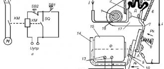
Induction (mechanical) electricity meters
Fig.1. Induction single-phase electric meter
Counters with a rotating disk are familiar to almost everyone. These are the ones that have a rotating wheel behind the transparent panel. Surely many have observed the speed of its rotation more than once - the higher the speed, the greater the energy consumption. And the counter readings are indicated by numbers on special reels.
The operating principle of such counters is as follows. The electric meter has 2 coils (Fig. 2 - 1 and 4 indexes) - a voltage coil (serves as an alternating current limiter, a barrier to interference, etc., creates a magnetic flux commensurate with the voltage) and a current coil (creates an alternating magnetic flux commensurate with the current ).
Fig.2. Operating principle of an induction electric meter
The magnetic fluxes created by the coils penetrate through the aluminum disk (Fig. 2, pointer 5). In this case, the flows created by the current coil penetrate the disk several times due to its U-shape. As a result, electromechanical forces appear, which rotate the disk.
Next, the disk axis interacts with the counting mechanism in the form of a worm (gear-screw) transmission (Fig. 3), which transmits the necessary signals and information to the digital reels. The higher the disk torque, the higher the power of the supplied signal (the torque is equal to the power of the network), and therefore the higher the power consumption.
Fig.3. Worm-gear
note
When the power of the supplied electromagnetic signal decreases, the permanent braking magnet comes into action (Fig. 2, pointer 3). It evens out fluctuations in the disk rotation frequency due to interaction with vortex flows. The magnet creates an electromechanical force opposite to the torsion of the disk. This causes the drive to slow down or stop altogether.
This group of meters is the cheapest and simplest. Induction electricity meters were widely used in Soviet times (and to this day, most apartments have just such devices installed).
But gradually they are being replaced by electronic meters due to a number of disadvantages of induction devices.
For example, an induction electric meter cannot take readings automatically, and there is often an error in the readings.
Advantages and disadvantages of induction meters
Advantages
- Reliable to use
- Long-term service life of the meter
- Independence from power fluctuations
- Cheaper than electronic ones
Flaws
- The accuracy class is quite low - 2.0; 2.5
- There is practically no protection against theft of electrical energy
- High self-current consumption
- At low loads the error increases (the lower the accuracy class, the greater the error)
- When metering several types of electricity (active and reactive), there is a need to use several energy metering devices
- Energy metering is carried out in one direction
- Large dimensions of devices
Electronic electricity meters
Fig.4. Electronic electricity meter
These devices are somewhat more expensive than induction ones, but today they are the most profitable and priority meters to use. They have a higher accuracy class and allow multiple tariffs to be taken into account.
Electronic electricity meters work by converting the analog input signal from the current sensor into a digital code equal to the power consumption. This code is sent to a special microcontroller to be decrypted. After that, the amount of electricity consumed is displayed on the display (or digital drum).
The most important component of these counters is the microcontroller. It is he who analyzes the signal and calculates the amount of electricity consumed. It also transmits information to output, electromechanical devices and display.
Fig.5. Operating principle of an electronic electricity meter
The device itself consists of a housing, a current transformer, a signal converter and a tariff module. If we look at it in more detail, the meter also includes:
- LCD (or digital drum)
- secondary power supply (converts AC voltage)
- microcontroller (calculates input pulses, calculates consumed electricity, exchanges data with other nodes and meter circuits)
- converter (converts an analog signal to a digital signal and then converts it into a pulse signal equal to the energy consumed)
- supervisor (generates a reset signal in case of power failures, outputs an alarm signal when the input voltage decreases)
- memory (stores electricity data)
- telemetry output (receives a pulse signal about energy consumption)
- real time clock (counts the current time and date)
- optical port (reads meter readings and also programs it)
Advantages and disadvantages of electronic electricity meters
Advantages
- Accuracy class - from 1.0 - high
- Multiple tariffs (from 2)
- One meter is enough to account for several types of electrical energy
- Energy accounting is carried out in 2 directions
- Measure the quality and volume of power
- Store electricity metering data
- Data is easily accessible
- In case of electricity theft, unauthorized access is recorded
- Possibility to take readings remotely
- Can be used for automated technical accounting and control of electricity metering (ASTUE and ASKUE)
- Long term metrological interval (MPI)
- Small in size
Flaws
- Very sensitive to voltage changes
- More expensive than induction
- Quite difficult to repair
Markings on electricity meters
In addition to the types of meters, there are several more nuances that you should know. Any electric meter has a certain marking, conventionally designated by letters and numbers.
Fig.6. Symbols on the electric meter
DesignationExplanation
| WITH | Device type (meter) |
| A, R | Type of energy taken into account (active energy/reactive energy) |
| ABOUT | Single phase meter |
| 3, 4 | Number of phase wires in the network (four-wire/three-wire) |
| U | Versatility |
| AND | Type of measuring system (induction meter). Next there may be a three-digit number, which indicates the design of the meter (the design of the meter can be induction or electronic). |
| T | Tropical meter type |
| P, M | Type of execution (direct-flow - if there is no connection to a transformer / modernized). Further, there may be abbreviations such as “380/220 17A, 2001,” which means operating voltages in the wires, maximum current flow and year of manufacture. Also at the end of the inscription there may be a serial number. |
As for the accuracy class of the electric meter, these parameters determine the accuracy of the readings of consumed electricity. Apartments, as a rule, have class 2.0 meters installed, but they can be higher.
What does this mean? And the fact is that your electric meter can take into account 2% more or less electricity from its own power. Or, more simply put, the meter error. The smaller the number, the smaller the error. In general, in domestic conditions, an electric meter of class 2.0 is sufficient.
Higher accuracy classes are more likely to be needed in enterprises where greater energy power is needed.
Important
So, today we don’t have to limit ourselves in choosing electricity meters. Each of them has its own specific features and functions. In this article, we examined the main features of these devices and the principles of their operation, which will help you navigate the variety of choices.
Source: https://www.diy.ru/post/6730/
The principle of operation of the electric meter
Everyone has an electricity meter in their home. And there is not a person who would not wonder how this unknown black box works, what it consists of, and whether it is really possible to make it spin in the opposite direction. Today we will satisfy your curiosity and look under the seal that blocks access to the internal structure of this very interesting device.
What types of electric meters are there?
Based on the operating principle of the counting mechanism, these devices are of three types:
- Mechanical - they are based on a gear reducer, which drives that same mysterious rotating disk.
- Electronic - the count is carried out by a pulse generator, the results are displayed on a liquid crystal display.
- Hybrid - the pulse generator is paired with a stepper motor, similar to those used in quartz watches. The results are given in the same way as with mechanical instruments - by numbers on bit rings driven by a gear reducer.
The most interesting thing is that the operating principle of the electric meter is based on the same phenomenon - electromagnetic induction.
And yet it spins!
The design of an electric meter is most clearly seen in the example of a single-phase household device of a mechanical type. Its circuit diagram is shown in the figure below.
- W-shaped core
- U-shaped core
- Gearbox
- Permanent magnet
- Disk
A coil with a small number of turns mounted on a U-shaped metal core is connected to terminals 1 and 2, into which the phase wire is clamped. It is called current because the connection is sequential. Another wire is also connected to terminal 1, going to another coil with a large number of turns and mounted on an W-shaped metal core.
The connection point is detachable, the fastener is a screw called a “voltage screw”, since the second end of the coil is connected to terminal 3, to which the neutral wire is connected and the connection is parallel. The coil cores are located at an angle of 900 to each other, and in the gap between them is the edge of the aluminum disk.
When an alternating electric current passes through the coils, a pulsating magnetic field is induced in the cores. Their product is a vortex magnetic flux, always rotating in one direction.
Advice
According to the law of electromagnetic induction, this vortex induces an electric current in the aluminum disk and forces it to rotate after itself.
Since both the voltage in the network and the current are taken into account, the consumption of electrical power is measured, which is the product of these quantities.
All this is very reminiscent of the design of an asynchronous single-phase electric motor with starting and operating windings. The only difference is that the electricity meter is a measuring machine, so for the accuracy of the readings, it is necessary to exclude all factors that can change them.
For example, moment of inertia. That is why the rotor, the role of which is played by the disk, is made of aluminum - the lightest electrically conductive material that is not subject to secondary magnetization. The disc-shaped shape was chosen because a side effect of electromagnetic induction is the heating of metals by so-called Foucault currents.
In flat-shaped conductors they attenuate faster. This property is used, for example, in high-voltage high-power transformers, the primary winding of which is made of a rectangular conductor.
The second difference between a mechanical counter and an asynchronous motor is the presence in its design of a brake - a permanent magnet located at the edge of the disk.
It is needed so that the rotation is uniform, without acceleration, and the stop occurs instantly, without coasting.
The position of this magnet can be changed by changing the amount of electrical power to which the device does not respond. The normal factory setting is 25W.
The disk is mounted on an axle, at one end of which there is a worm gear. Through it the gearbox of the counting mechanism is activated. Changing the positions of the windings can indeed lead to reversal.
note
To do this, you just need to change the connection order: apply the phase to terminal 3 and remove it from the fourth. To combat fraud, a ratcheting mechanism is installed in the gearbox that blocks rotation in the opposite direction.
Three-phase mechanical counting devices are designed in a similar way.
But there are subtleties: if the circuit is built with a solidly grounded neutral - the phases at the output of the substation power transformer are connected by a star and the line consists of three conductors, then the meter has two disks on the same axis.
How to check the meter yourself
To check the functionality of the meter, you need to carry out several steps:
- You need to make sure that the device is correctly connected to a 220 or 380 V network in accordance with the diagram.
- Check that the disk does not rotate randomly. To do this, you need to turn off all the machines in the panel and wait a while. If the counter still spins, it is faulty.
- Checking magnetization. The influence of the magnet also changes the operation of the device. You can check its presence using a small metal needle or a special device.
Checking the device using special instruments
An electronic meter is an expensive but accurate device that will help you save on electricity bills in the future. The complexity of the design ensures ease of operation, but also causes frequent breakdowns.
You might be interested in Load power regulator
Asynchronous or pulsating counters
The logic circuit of a 2-bit ripple counter is shown in the figure. Trigger (T) is used. But we can use flip-flop JK also with J and K permanently connected to logic 1. The external clock is applied to the clock input of flip-flop A and the output of QA is applied to the clock input of the next flip-flop i.e. FF-B.
Logic Diagram
operation
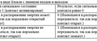
| SN | State | operation |
| 1 | First let both FFs be in reset state | QBQA = 00 initially |
| 2 | After 1st negative clock edge | As soon as the first negative clock is applied, FF-A will switch and QA will be equal to 1. QA is connected to the clock input of FF-B. Since QA has changed from 0 to 1, FF-B treats it as a positive edge of the clock signal. There is no change in QB because FF-B is FF caused by negative edge. QBQA = 01 after the first clock pulse. |
| 3 | After the 2nd negative clock edge | Upon arrival of the second negative clock edge, FF-A switches again and QA = 0. The QA change acts as a negative clock edge for FF-B. So he will also switch and the QB will be 1. QBQA = 10 after the second clock pulse. |
| 4 | After the 3rd negative clock edge | Upon reaching the 3rd negative clock edge, FF-A switches again and QA becomes 1 of 0. Since this is a positive change, FF-B does not react to it and remains inactive. Thus, QB does not change and remains equal to 1. QBQA = 11 after the third clock pulse. |
| 5 | After the 4th negative clock edge | Upon reaching the 4th negative clock edge, FF-A switches again and QA becomes 1 of 0. This negative change in QA acts as a clock pulse for FF-B. Hence, it switches to change the QB from 1 to 0. QBQA = 00 after the fourth clock pulse. |
As soon as the first negative clock is applied, FF-A will switch and QA will be equal to 1.
QA is connected to the clock input of FF-B. Since QA has changed from 0 to 1, FF-B treats it as a positive edge of the clock signal. There is no change in QB because FF-B is FF caused by negative edge.
QBQA = 01 after the first clock pulse.
Upon arrival of the second negative clock edge, FF-A switches again and QA = 0.
The QA change acts as a negative clock edge for FF-B. So he will also switch and the QB will be 1.
QBQA = 10 after the second clock pulse.
Upon reaching the 3rd negative clock edge, FF-A switches again and QA becomes 1 of 0.
Since this is a positive change, FF-B does not react to it and remains inactive. Thus, QB does not change and remains equal to 1.
QBQA = 11 after the third clock pulse.
Upon reaching the 4th negative clock edge, FF-A switches again and QA becomes 1 of 0.
This negative change in QA acts as a clock pulse for FF-B. Hence, it switches to change the QB from 1 to 0.
QBQA = 00 after the fourth clock pulse.
Truth table
Model rating
During the time that electronic water meters have been on the market, buyers have managed to form their opinion about the most successful models. Below are the best of them.
AQUA 2 with radio module
has released a model that works using the built-in Nina, NB-IoT, LTE-M, GSM protocol and is designed for measuring DHW and cold water. The device can be used either independently or as part of a complex of automated systems. Approximate market value is 2300 rubles.
SKV 15-3-7 with STRIZH radio modem
The device has the function of remote monitoring of readings via the Internet. The calibration interval is 6 years, and the maximum pressure can withstand up to 1 MPa. Used to measure both cold and hot water. Transfers readings to the consumer’s personal account or directly to the water supply company. The approximate cost on the market is 3350 rubles.
ELEHANT SVD-15 with installation kit
The device is manufactured in Omsk and has a number of advantages. The readings are transmitted via a radio channel to the consumer’s smartphone and can be displayed on an external display. Without additional equipment, you can also output data to the management company.
Low cost (about 1000 rubles) and easy to install. There is no need to install a check valve, which makes it possible to save money and avoid another connection. Suitable for cold and hot water.
Advantages and disadvantages
An electronic water meter has the following advantages:
Convenient reading of readings, thanks to the free arrangement of the electronic display, the possibility of remote data transfer, transfer of readings directly to the service provider.- Accuracy of readings that does not decrease over time.
- Payment is only for hot water supplied “after the fact”. Thanks to the built-in thermometer, the consumer pays only for the hot water that was actually supplied to him.
- Long verification interval. Electronic water meters are generally verified every 8-10 years. To do this, you can remove only the upper, electronic part of the mechanism, rather than disassemble the entire device.
- Possibility of installing the device both horizontally and vertically.
- An ideal option for a “smart home”, where functions in the house are as automated as possible. Prevents leaks: when the device detects a continuous flow of water for an hour, it automatically closes the solenoid valve and notifies of a leak.
- The water meter's power supply is autonomous, so voltage surges will prevent the mechanism from becoming unusable.
- An electronic water meter is considered a more durable and high-quality device than a mechanical one.
- With the help of additional systems, you can not only monitor water consumption, but also regulate its supply, reducing its consumption.
In addition to the advantages, before purchasing an electronic water meter, it is worth familiarizing yourself with the disadvantages:
- High cost of the device.
- Requirement for a power source. For uninterrupted operation of the device, it is necessary to organize constant operation from the network or periodically replace the battery. High-quality batteries can last up to 3 years without replacement.
Instructions for use
The operating and installation instructions contain the following points:
- The device can be installed by personnel who have undergone safety training and have an electrical safety qualification group of at least level III (electrical installation up to 1000 V).
- Before installation, you must remove the device from the transport packaging and carry out an external inspection.
- Make sure that the housing and protective cover of the junction box are not significantly damaged.
- Install the meter at the workplace, remove the protective cover of the distribution box and connect it to the voltage circuit
Important! Connect to the network only with the power turned off
- Install the junction box cover and secure it with two screws.
- Turn on the power and make sure the meter is on: the indicator shows the energy value counted in the current zone.
- Note the date of installation and the date of commissioning in the table.
Installation of the meter in the panel