To fix the frequency, a frequency meter is used; this is a special electrical measuring device used to fix the frequency of a periodic process or the frequencies of the harmonic components of the signal spectrum.
One of the main parameters of periodic and pulsating currents is frequency, which determines the number of periodic oscillations per full cycle and is the main characteristic of the SI system of units. The need for an accurate determination of frequency arises in various fields of scientific and practical activity; its determination is of particular importance in electrical engineering, radio electronics, telecommunications, etc.
Frequency meter
Currently, it is possible to measure frequency using a variety of instruments:
- this is also a multimeter
- and a generator with built-in frequency counters
- and oscilloscope
A specialized device that performs time-frequency measurements is a frequency meter.
Classification of frequency meters
Frequency meters are divided depending on the following parameters:
By measurement method:
- frequency counters for direct evaluation (for example, analogue)
- comparison frequency meters (heterodyne, resonant, electronic counting)
According to the physical meaning of the measured quantity, frequency meters are designed to:
- for measuring sinusoidal oscillations (analog)
- measurements of frequencies of harmonic components (resonant, heterodyne, vibration)
- for measuring discrete events (capacitor, electronic counting)
According to their design, they are divided into:
- panel
- portable
- stationary
By area of application:
- electrical measuring (analog dial, resonant frequency meters, and also partially capacitor and electronic counting frequency meters)
- radio measuring (heterodyne, resonant, capacitor, electronic counting frequency meters)
Electronic frequency counters
- The operating principle of electronic frequency counters (ECFs) is based on counting the number of pulses generated by input circuits from a periodic signal of arbitrary shape over a certain time interval. The measurement time interval is also set by counting pulses taken from the internal quartz oscillator of the ESC or from an external source (for example, a frequency standard). Thus, the ESC is a comparison device, the measurement accuracy of which depends on the accuracy of the reference frequency.
- ESC is the most common type of frequency meters due to its versatility, wide frequency range (from fractions of a hertz to tens of megahertz) and high accuracy. To increase the range to hundreds of megahertz - tens of gigahertz, additional blocks are used - frequency dividers and frequency carriers.
- In addition to frequency, most ESCs allow you to measure the pulse repetition period, time intervals between pulses, the ratio of two frequencies, and can also be used as pulse number counters.
- Some ESCs (for example Ch3-64) combine electronic counting and heterodyne measurement methods. This not only expands the measurement range, but also makes it possible to determine the carrier frequency of pulse-modulated signals, which is not possible with a simple counting method.
- PURPOSE:
maintenance, adjustment and diagnostics of radio-electronic equipment for various purposes, monitoring the operation of radio systems and technological processes - EXAMPLES:
Ch3-33, Ch3-54, Ch3-57, Ch3-63, Ch3-64, Ch3-67, Ch3-84
What is measured with what, what frequency meters, for what?
With the help of resonant frequency meters, coupled with converters of mechanical vibrations into electrical ones, the frequency of mechanical vibrations is usually measured.
Using electromechanical, electrodynamic, electronic, electromagnetic, magnetoelectric frequency meters, the frequency of electrical oscillations is measured.
Electronic frequency meters (resonant, heterodyne, digital, etc.) are used to measure the frequency of electromagnetic oscillations in the radio frequency and microwave ranges.
The operation of a resonant frequency meter is based on a comparison of the frequency measured with the natural frequency of an electrical circuit (or microwave resonator), which is tuned to resonance with the measured frequency. In heterodyne frequency meters, the measured value is compared with the known frequency (or its harmonics) of the local oscillator (model oscillator). The principle of operation of digital frequency meters is to count the number of periods of measured oscillations over a certain period of time.
By adding appropriate attachments to the electronic frequency meter, it is possible to measure almost any electrical quantity (voltage, current, resistance, capacitance, inductance, etc.).
Design and components of a digital frequency meter
Definition 2
A digital frequency meter is a frequency meter that can be used to measure the period and frequency of electrical signals of various shapes, as well as the duration of pulses and the frequency ratio of two electrical signals.
A digital frequency meter is used to determine the frequency of pulsed or alternating electric current during the process of tuning radio equipment. This device is also often used in power plants to monitor the frequency of alternating current supplied to power lines.
Signal parameters are measured by comparing one long time interval with a set of smaller ones. In this case, one interval is measured, and the other is exemplary. Quantization (comparing and replacing a long time interval with a set of shorter ones) occurs automatically.
To measure different parameters in digital frequency meters, the same units are used, switched by a switch for the type of operation of the device. Thanks to this, various structural diagrams are formed that make it possible to measure the selected parameter. The main components of a digital frequency meter include:
Finished works on a similar topic
Course work Digital frequency meters 430 ₽ Abstract Digital frequency meters 280 ₽ Test work Digital frequency meters 250 ₽
Receive completed work or specialist advice on your educational project Find out the cost
- Frequency divider.
- Electronic key.
- Digital readout device.
- Shapers.
- Stable frequency pulse generator.
- A control device that is auxiliary.
The tasks of the control device are to prepare the main components of the frequency meter for measurements, as well as to ensure automatic, manual or remote start of the device. The digital frequency meter controls are displayed on the front panel. Different modifications and types of digital frequency meters have different controls.
Regulatory and technical documentation
GOST 8.567-99 GSI. Time and frequency measurements. Terms and definitions GOST 7590-93 Analog indicating electrical measuring devices of direct action and auxiliary parts for them. Part 4. Special requirements for frequency meters GOST 7590-78 Analog indicating electrical instruments for measuring frequency. General technical conditions GOST 22335-85 Electronic frequency counters. Technical requirements, test methods GOST 22261-94 Instruments for measuring electrical and magnetic quantities. General technical conditions GOST 8.422-81 GSI. Frequency meters. Methods and means of verification GOST 12692-67 Resonant frequency meters. Methods and means of verification OST 11-272.000-80 Resonant frequency meters. Main parameters of MI 1835-88 Electronic frequency counters. Verification method
Resonant frequency meters
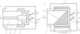
The operating principle of resonant frequency meters is based on comparing the frequency of the input signal with the natural resonant frequency of the tunable resonator. An oscillatory circuit, a section of a waveguide (cavity resonator) or a quarter-wave section of a line can be used as a resonator. The controlled signal is supplied to the resonator through the input circuits; from the resonator, the signal is fed through the detector to the indicator device (galvanometer). To increase sensitivity, some frequency counters use amplifiers. The operator adjusts the resonator according to the maximum indicator reading and counts the frequency using the tuning dial.
- PURPOSE:
configuration, maintenance, control of the operation of transceiver devices, measurement of the carrier frequency of modulated signals - EXAMPLES:
Ch2-33, Ch2-34, Ch2-45, Ch2-55
Capacitor frequency meters
Electronic capacitor frequency meters are used to measure frequencies in the range from 10Hz to 1MHz. The principle of such frequency meters is based on the alternating charging of capacitors from a battery with its subsequent discharge through a magnetoelectric mechanism. This process is carried out with a frequency equal to the measured frequency, since switching is carried out under the influence of the voltage being tested itself. During one cycle, a charge Q =CU will flow through the magnetoelectric mechanism, therefore, the average current flowing through the indicator will be equal to I_avg=Qf_x=CUf_x. Thus, the readings of the magnetoelectric ammeter turn out to be proportional to the measured frequency. The main reduced error of such frequency meters lies within 2-3%.
- PURPOSE:
setting up and maintaining low-frequency equipment - EXAMPLES:
F5043
Amateur radio measurements: when there is no frequency meter
In amateur radio practice, due to budget limitations, a situation often arises when one or another device needed for work is not available.
In such a situation, it is necessary to calculate the required parameter based on the results of indirect measurements, i.e. “drill with a saw and saw with a gimlet.” In the process of debugging the device I was developing, it became necessary to calibrate the digital frequency synthesizer included in this device. The task is trivial if you have an electronic counting frequency meter (ECF). The problem was that I was unable to “borrow” the frequency meter. If we describe the operation of the frequency synthesizer used in the device quite simply, it produces a signal at the output with a frequency of Fs
by processing the input signal from a reference oscillator with a frequency
Fxo
:
An inexpensive quartz resonator marked on the case “ TXC 25.0F6QF
” was used as a frequency-setting element of the reference oscillator.
The exact frequency of the reference oscillator signal was not known. In the synthesizer settings, the reference frequency was specified by the constant 25000000 Hz
.
The frequency synthesizer itself was programmed to output a signal with a frequency of 9996 kHz
. To check the functionality of the synthesizer, a Rigol DS1102E digital oscilloscope was used. Frequency measurement was enabled in the channel settings.
The oscilloscope at the terminals of the quartz resonator showed a measured value of 25.00 MHz, and at the output of the synthesizer - 10.00 MHz. In principle, this was already not bad: the scheme worked.
An analogue of calibrating frequency-setting circuits using the beat method is the technique of tuning musical instruments using a tuning fork. The sound extracted from the instrument is superimposed on the sound of the tuning fork. If the tones do not match, a clearly audible “beat” of frequency appears. The tone of a musical instrument is adjusted until “zero beats” appear, i.e. states when the frequencies coincide. The easiest way to calibrate the frequency synthesizer using the beat method was to use a radio receiver with a panoramic indicator and the signal from the RWM radio station as a control signal.
SoftRock RX Ensemble II with HDSDR program was used as a control receiver. The receiver scale was previously calibrated using signals from the RWM radio station at all three frequencies: 4996000, 9996000 and 14996000 Hz. 9996000 Hz was used as a control signal
.
The screenshot shows the reception of RWM second marks at a frequency of 9996000 Hz
and receiving the synthesizer output signal at a frequency of approximately
9997970 Hz
.
When setting the frequency of the synthesizer, a constant of 25,000,000 Hz
(the nominal frequency of the quartz resonator) was used.
During calibration, this constant was multiplied by the ratio of frequencies 9997970 Hz
and
9996000 Hz
.
As a result, the actual starting frequency of the quartz resonator was 25004927 Hz
. This value was entered as a constant into the device firmware. The screenshot shows the result of the calibration:
Synthesizer output frequency 9996 kHz
exactly matches the RWM second mark reception frequency at
9996000 Hz
.
After calibration, the oscilloscope showed 25.00 MHz at the quartz resonator terminals, and 10.00 MHz at the synthesizer output, i.e. the same values as before calibration.
In Perm, during daylight hours the RWM signal is stably received at a frequency of 9996 kHz, and in the dark - at a frequency of 4996 kHz. If radio wave transmission is unstable and RWM signals are not being received, hfcc.org can be used to find frequencies and schedules for broadcast radio stations.
Carrier signals from broadcast stations can also, if necessary, be used as control signals, because they usually have a frequency deviation of no more than 10 Hz from the broadcast frequency.
Brief conclusions
The simplest and most accurate way to measure the frequency of a signal in the radio range is to measure the frequency with an electronic frequency counter.
You can obtain an approximate value of the signal frequency by receiving it at a control receiver with a calibrated scale.
When using a control receiver, the exact value of the signal frequency can be obtained from the “zero beats” of the measured signal with the control signal received from the reference source.
Required additions:
The synthesizer could be calibrated:
- Of course, with the help of ESC.
- By the beat method using a professional receiver without a panoramic indicator, for example, R-326, R-326M, R-250M2, etc. and RWM signals “by ear”. It would not be as clear as with a panoramic indicator and would take more time.
- Using a calibrated generator and oscilloscope using Lissajous patterns. It looks very impressive, but requires additional expensive equipment.
And yet, the scope of use by radio amateurs of the radio receivers mentioned above is very wide. They are used for monitoring the airwaves, for monitoring the passage of radio waves, for monitoring signals when tuning radio stations, etc.
Analog dial frequency meters
Analog frequency meters, according to the measuring mechanism used, are of electromagnetic, electrodynamic and magnetoelectric systems. Their operation is based on the use of a frequency-dependent circuit, the impedance module of which depends on the frequency. The measuring mechanism, as a rule, is a ratiometer, to one arm of which the measured signal is supplied through a frequency-independent circuit, and to the other through a frequency-dependent circuit; the rotor of the ratiometer with the arrow, as a result of the interaction of magnetic fluxes, is set to a position depending on the ratio of currents in the windings. There are analog frequency meters that operate on different principles.
- PURPOSE:
monitoring the power supply network - EXAMPLES:
D416, E353, Ts1736, M800, S 300 M1-1
Vibration (reed) frequency meters
The dashboard of an airfield air conditioner with a frequency meter showing 49.5 Hz
is a device with a moving part in the form of a set of elastic elements (plates, reeds) set into resonant oscillations when exposed to an alternating magnetic or electric field. Most often, an electromagnet is used to excite oscillations and steel plates as elements. The element whose natural frequency is closest to the frequency of the current flowing through the electromagnet winding enters resonance and oscillates with the greatest range, which is displayed visually.
- PURPOSE:
monitoring the power supply network - EXAMPLES:
B80, B87
Names and designations
- Outdated names Wave meter
- for resonant and heterodyne frequency meters - Hertzmeter
- for panel analog and reed frequency meters
- B
xx - vibration frequency meters
xx - devices of the electrodynamic system
xx - devices of the electromagnetic system
xx - devices of the magnetoelectric system
xx - rectifier system devices
xx,
Shch
xx - electronic system devices
xx - recording devices
- Ch2-
xx - resonant frequency meters
xx,
RF3-
xx - Electronic frequency counters
xx - heterodyne, capacitor and bridge frequency meters