As you know, an insulated neutral central line is not used in apartment or home electrical wiring. However, for transformers and high-voltage generators, it is an integral part of the entire electrical network.
In this article we will delve into the terminology and scope of the isolated neutral type.
IT grounding system or isolated neutral grounding system.
Typically this system is described something like this:
The classic system, the main feature of which is the isolated neutral of the source - “I”, as well as the presence of a protective grounding circuit on the consumer side - “T”. Voltage from the source to the consumer is transmitted through the minimum possible number of wires, and all conductive parts of the consumer equipment housings must be reliably connected to the grounding electrode. There is no zero functional conductor N in the source-consumer section in the IT system architecture.
This is where the entire description of the IT system is usually limited and it is not at all clear how to practically use it all? How to connect consumers, how to connect automation systems?
First of all, it is not clear - if the linear voltage is 380 V and the phase voltage is 220, then how will a single-phase load work? After all, there is no zero, that is, it is actually torn off. What happens when the zero breaks? That's right, everything will go to pieces - it will either burn out or simply not want to work. How do we get out of this dissonance in the IT system? Let's listen to Vasily further.
I will try to answer these questions.
First, where can one meet this system?
It is widely used on ships and anything that is considered a ship, on offshore oil and gas platforms, for example. It doesn’t matter that the platform is at the bottom of the sea, from the point of view of the maritime register it is a ship
Description of the isolated device
Such a protection device is a system where the neutral wire of the generator or transformer is not connected to the ground electrode. Connection to solid grounding is allowed through signaling, protection and measuring equipment, which have high resistance.
In this case, the isolated neutral is a three-phase network connected from the electrical equipment to ground through resistors.
In this case, a system with capacitors is connected in parallel. This neutral connection diagram has two components:
- active;
- reactive.
The active circuit is designed to prevent leakage current using resistors, which, due to their high resistance, reduce its value to a minimum. The reactive system has capacitors in which one plate is connected to the line, and the second to ground.
How to connect a single-phase load in a system with an isolated neutral?
There are two options here:
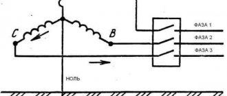
1) Oil ships often have two parallel three-phase lines, a 0.4 kV 3 phase line and a 230 V 3 phase line. To connect a device intended for use in a 230V network, you need to connect it to a 230V network BETWEEN TWO PHASES, i.e. to line voltage.
That is, use not a “star” circuit, as is usually done to obtain 220V, but a “triangle” circuit, connecting a 220 V load (which for some reason does not dare to be called “single-phase”) to one of the sides of the “triangle”.
2) Use a transformer, for example a step-down transformer 3Ph 400V / 3Ph 230V. There are also two options with a transformer, after it there can also be an IT system, or the transformer can provide an artificial neutral on the secondary winding.
Typically a 380/220 V transformer is used, the primary winding of which is connected to any two phases. If grounding is needed, then one of the terminals of the secondary winding is “solidly” grounded, and a TN-S (or, rather, TN-CS) system is obtained. With the right choice of circuit breaker and RCD, the system will provide excellent protection against short circuits and direct contact.
However, a system in which none of the transformer terminals is connected to the housing will be safer. The transformer can be anything, the main thing is that its output has a voltage of 220 V - it doesn’t matter whether it’s linear or phase.
There are usually no problems with connecting electric motors, valves and the like, but there may be problems with automation. They are due to the fact that not all devices operate correctly when their power is turned on to a linear voltage of 230 V (between phases). If you encounter this problem, you can get out of the situation either by replacing the device, or by using a low-power transformer with an artificial zero after the secondary winding.
Theoretically, yes, the device does not care where the 220V voltage comes from. But in practice, for example, instead of measuring a 4-20 mA signal, they begin to show some kind of heresy, despite the fact that the sensors are obviously working. You turn it on to ordinary phase voltage - everything works. Apparently, something is wrong with the architecture of specific devices. It doesn't happen often, but I've come across it a couple of times.
What it is
The definition of “isolated neutral” is given in Chapter 1.7. PUE, in paragraph 1.7.6. and GOST R 12.1.009-2009. Where it is said that the neutral of a transformer or generator is called isolated when it is not connected to a grounding device at all, or when it is connected through protection, measurement, and alarm devices.
The neutral is the point at which the windings of transformers or generators are connected when switched on in a star configuration.
There is a misconception among electricians that the abbreviated name for an insulated neutral is an IT system, according to the classification of clause 1.7.3. Which is not entirely true. The same paragraph states that the designations TN-C/CS/S, TT and IT are accepted for networks and electrical installations with voltages up to 1 kV.
In the same chapter 1.7 of the PUE there is paragraph 1.7.2. where it is said that with regard to electrical safety measures, electrical installations are divided into 4 types - isolated or solidly grounded up to 1 kV and above 1 kV.
Thus, there are some differences in the safety and application of such a network in different voltage classes, and calling a 10 kV line with an isolated neutral “IT system” is at least incorrect. Although schematically it’s almost the same.
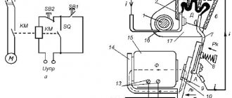
Example IT diagram
For an example of a practical circuit, see the fragment of the DC rectifier cabinet wiring diagram. Please note that the power is supplied from a 3-phase 230 V network, each of the three rectifiers is connected between phases, in line voltage.
An example of constructing a circuit with an IT grounding system
In fact, there is a protective grounding wire, it comes from the supply generator, but it only serves to ground the power supply housings.
In this case, the output voltage is constant 12 V, but can be anything! And the “minus” of all power supplies is grounded. The outputs of each power supply are supplied to the loads through circuit breakers (not shown).
I hope it has become clearer how connecting consumers to the IT system practically works. Thank you for your attention.
Voting for this and other articles will be open in about a month, follow the news in the VK SamElectric.ru group! If anyone hasn’t subscribed, I recommend it, there’s still a lot of interesting things waiting for us!
Vasily Vasilievich, author of an article about the IT grounding system
Why is the neutral wire thinner than the phase wires?
The neutral wire is made thinner than the phase wires, because the current that flows through it is less than the current that flows through the phase wires.
If the load across the phases in the network is distributed (strictly) evenly, the currents in it flow from phase wires to other phase wires. The voltage drop in the network will be such that the neutral potential will be on the neutral bus and the current in the neutral wire will be zero. When the loads are uneven, a current appears in the neutral wire. The greater the unevenness, the larger it is.
Three-phase networks with effectively grounded neutrals
In networks of 110 kV and above, the determining factor in the choice of neutral grounding method is the cost of insulation. Here, effective neutral grounding is used, in which during single-phase faults the voltage on the undamaged phases relative to the ground is approximately 0.8 phase-to-phase voltage in normal operation. This is the main advantage of this method of neutral grounding.
Fig.6. Three-phase network with effectively grounded neutral
However, the neutral mode under consideration also has a number of disadvantages. Thus, when one phase is short-circuited to ground, a short-circuited circuit is formed through the ground and the neutral of a source with low resistance, to which the phase EMF is applied (Fig. 6). A short circuit mode occurs, accompanied by the flow of large currents. To avoid equipment damage, prolonged flow of high currents is unacceptable, therefore short circuits are quickly switched off by relay protection. True, a significant part of single-phase faults in electrical networks with voltages of 110 kV and higher are self-repairing, i.e. disappearing after the tension is removed. In such cases, automatic reclosing devices (ARDs) are effective, which, acting after the operation of relay protection devices, restore power to consumers in a minimum time.
The second disadvantage is the significant increase in the cost of the grounding loop installed in switchgears, which must divert large short-circuit currents to the ground and therefore in this case represents a complex engineering structure.
The third drawback is the significant single-phase short-circuit current, which, with a large number of grounded neutrals of transformers, as well as in networks with autotransformers, can exceed the three-phase short-circuit currents. To reduce single-phase short circuit currents, if possible and effective, partial ungrounding of the neutrals is used (mainly in 110-220 kV networks). It is possible to use current-limiting resistances connected to the neutrals of transformers for the same purposes.
Three-phase networks with resonantly grounded (compensated) neutrals
In 3-35 kV networks, to reduce the ground fault current in order to meet the above standards, grounding of neutrals through arc suppression reactors is used.
In normal operation, the current through the reactor is practically zero. In the event of a complete ground fault of one phase, the arc suppression reactor is under phase voltage and, along with the capacitive current IC, the inductive reactor current IL also flows through the ground fault (Fig. 3). Since inductive and capacitive currents differ in phase by an angle of 180°, at the point of a ground fault they cancel each other out. If IC=IL (resonance), then no current will flow through the ground fault. Thanks to this, an arc does not occur at the site of damage and the dangerous consequences associated with it are eliminated.
Fig.3. Three-phase network with resonantly grounded neutral
The total power of arc suppression reactors for networks is determined from the expression
Q = n IC UФ, (6)
where n is a coefficient taking into account the development of the network; approximately n = 1.25 can be taken; IC—total ground fault current, A; UФ - phase voltage of the network, kV.
Based on the calculated Q value, reactors with the required rated power are selected in the catalog. It is necessary to take into account that the adjustment range of the reactors must be sufficient to ensure the most complete compensation of the capacitive current in the event of probable changes in the network diagram (for example, when disconnecting lines, etc.). When IC ≥ 50 A, two arc suppression reactors are installed with a total power according to (6).
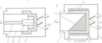
Rice. 4. Design of arc suppression reactors: a - RZDSOM type, b - RZDPOM type
In Russia, various types of arc suppression reactors are used. The most common are reactors of the RZDSOM type (Fig. 4, a) with a power of up to 1520 kV A for a voltage of up to 35 kV with a control range of 1:2. The windings of these reactors are located on a composite magnetic core with alternating air gaps and have taps to regulate the compensation current. The reactors are oil cooled.
More accurately, smoothly and automatically, it is possible to adjust the compensation in RZDPOM reactors, the inductance of which changes with a change in the non-magnetic gap in the core (Fig. 4, b) or by biasing the magnetic core steel from a direct current source.
Arc suppression reactors must be installed at node supply substations connected to the compensated network by at least three lines. When compensating generator voltage networks, reactors are usually located near generators. The most typical methods for connecting arc suppression reactors are shown in Fig. 5.
Fig.5. Placement of arc suppression reactors in the network
Figure 5,a shows two arc suppression reactors connected to the neutral point of the substation transformers, Figure 5.b shows a reactor connected to the neutral point of a generator operating in a block with a transformer. The diagram in Fig. 5, c shows the connection of the arc suppression reactor to the neutral of one of two generators operating on common busbars. It should be noted that in this case, the reactor connection circuit must pass through the window of the core of the zero sequence current transformer (ZCT), which is necessary to ensure proper operation of the generator protection against ground faults.
When connecting arc suppression reactors through special transformers and auxiliary transformers, the power of which is commensurate with the power of the reactors, it is necessary to take into account their mutual influence.
First of all, this influence is reflected in a decrease in the actual compensation current compared to the nominal one due to the presence of the transformer winding resistance connected in series with the reactor
(7)
where Inom,p is the rated current of the arc suppression reactor; Uк% - short-circuit voltage of the transformer; Snom,t - rated power of the transformer.
The limiting effect of the transformer windings is especially pronounced when using a star-star winding connection circuit, since with single-phase ground faults their inductive reactance is approximately 10 times greater than with phase-to-phase short circuits. For this reason, transformers with a star-delta winding connection circuit are preferable for connecting reactors. In turn, the presence of an arc suppression reactor in the neutral of the transformer causes an additional load on its windings during single-phase ground faults, which leads to increased heating. This is especially important to consider when using transformers with a load on the low voltage side to connect the reactor, for example, auxiliary transformers of power plants and substations. The permissible power of the reactor connected to the loaded transformer is determined from the expression
(8)
where Snom,t is the rated power of the transformer; Smax - maximum load power.
Expression (8) is valid taking into account the fact that the load cosφ value is usually close to unity, and the active resistance of the reactor is small.
Taking into account the overload of the transformer, permissible for the duration of operation of the network with a grounded phase and determined by the overload capacity coefficient kper, the permissible power of the reactor connected to this transformer is equal to
(9)
When connecting the reactor to a special unloaded transformer, the condition must be met (if the transformer overload is permissible).
In networks with a resonantly grounded (compensated) neutral, as well as in networks with ungrounded neutrals, temporary operation with a phase closed to ground is allowed until it is possible to make the necessary switchings to separate the damaged section. In this case, the permissible continuous operation time of the reactor (6 hours) should also be taken into account.
The presence of arc suppression reactors is especially valuable during short-term ground faults, since in this case the arc at the fault point goes out and the line does not turn off. In networks with neutrals grounded through an arc suppression reactor, during single-phase ground faults, the voltages of two undamaged phases relative to the ground increase by √3 times, i.e. to phase-to-phase voltage. Consequently, in their basic properties these networks are similar to networks with ungrounded (isolated) neutrals.
Features of solid grounding
Neutral grounding in dead mode is provided for four-wire AC networks. In such cases, the neutral terminals of power transformers are solidly grounded. All parts to be grounded and the neutral grounded terminal are connected. The neutral wire must be solid, without fuses or any disconnecting devices.
As a solidly grounded neutral of overhead lines with voltages up to 1 kilovolt, a neutral wire is used, laid together with the phase lines on the same supports.
All branches or ends of overhead lines over 200 meters in length are subject to re-grounding of the neutral wire. The same applies to inputs into buildings where there are installations that must be grounded. Reinforced concrete supports, as well as grounding devices that protect against lightning surges, can be used as natural grounding conductors.
Thus, an isolated and solidly grounded neutral ensures normal operation of the relay protection of generators and transformers. In addition, they reliably protect people from electric shock.
Advantages and disadvantages
One of the most important advantages of the mode of such networks is the presence of a small current during single-phase ground faults. This fact makes it possible to significantly increase the operation of circuit breakers. The fact is that ground faults in practice account for 90% of the total number of emergency situations.
In addition, the presence of low current reduces the requirements for grounding equipment. This neutral mode also has many disadvantages. For example, a single-phase ground fault can cause ferroresonance phenomena, which often lead to failure of electrical equipment.
Arc overvoltages may occur, converting a single-phase fault into a two- and three-phase fault. In addition, the design of short circuit protection is quite complex, which leads to its insufficient performance and efficiency. There is an opinion that with a single-phase short circuit, further operation of electrical equipment is possible.
But practice shows that two- and three-phase short circuits , which ultimately lead to a shutdown of electrical equipment. When a wire falls near power line supports and a short circuit persists, dangerous touch voltages appear. Most deaths occur in such situations.
Therefore, for uninterrupted operation of power supply in networks with isolated neutrals, automatic switching on of backup power is used.