Very often, when performing repair or installation work related to electricity in an apartment, house, garage or country house, it becomes necessary to find zero and phase. This is necessary for the correct connection of sockets, switches, and lighting fixtures. Most people, even if they do not have special technical education, imagine that there are special indicators for this. We will briefly look at this method, and also tell you about another device that no professional electrician can do without. Let's talk about how to determine phase and zero with a multimeter.
Concepts of zero and phase
Before determining phase zero, it would be good to remember a little physics and figure out what these concepts are and why they are found in a socket.
All electrical networks (both domestic and industrial) are divided into two types - with direct and alternating current. From school we remember that current is the movement of electrons in a certain order. With constant current, electrons move in one direction. With alternating current, this direction is constantly changing.
We are more interested in the variable network, which consists of two parts:
- The working phase (as a rule, it is simply called the “phase”). Operating voltage is supplied to it.
- An empty phase, called “zero” in electricity. It is necessary to create a closed network for connecting and operating electrical appliances, and also serves to ground the network.
When we connect devices to a single-phase network, it is not particularly important where exactly the empty or working phase is. But when we install electrical wiring in an apartment and connect it to the general house network, it is necessary to know this.
The difference between zero and phase in the video:
Alternative methods without the use of instruments
If the situation is such that there is neither an indicator screwdriver nor a multimeter, but it is necessary to find out which contact is phase, use a visual method for determining the contact.
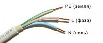
On the cable there is often a letter designation of the characteristics of the conductors. So, the letter L is assigned to the “phase”, N to the “zero”, and PE to the “earth”.
Sometimes electricians during installation additionally mark the phase wire with a hanging tag with a designation. But a simpler solution is color coding of wires. Connecting them correctly (in accordance with the standard) subsequently makes the work of electricians easier, allowing them to quickly navigate the wiring.
Identification by color marking
The required core can be determined by the color of the insulation.
The easiest way to find the required core is to determine by the color of the insulation. The color of wires in electrical wiring and its designation are regulated by state standards. According to the international IEC standard, manufacturers are required to paint the insulation of each core in a different color. In a single-phase network, the color of the wires in a 220 V electrical wiring is as follows: zero should be blue or light blue, ground should be yellow-green (sometimes in the form of a stripe), the phase can have any other shade. Typically the color used for the phase core is brown. In a two-core wire, the zero is blue, the phase is of a different color. What color a phase is in a multiphase network depends on the manufacturer. Usually it is black, brown, red.
This method of determination is not reliable. Not all manufacturers adhere to the established requirements, so the cores may be designated differently. It is especially dangerous to use a search by color marking in old houses - all the veins there were white.
Visually
When describing the visual method of identifying conductors, it was clarified that in most modern electrical networks, yellow-green color corresponds to a protective zero, all shades of blue indicate a working zero, and any other colors indicate a phase.
However, it must be taken into account that conductors may not correspond to the accepted color scheme in the following cases:
- The wiring was laid in an old house, where the home electrical network was not reconstructed in accordance with modern rules. Most often it uses single-color conductors.
- The wiring was installed in a new building, but its installation was carried out by private individuals and not by professional electricians.
- Wires lead to more complex household devices, for example, various switches or switches, the design of which initially implies a fundamentally different functioning scheme.
- The wiring was laid according to standards different from those accepted in Europe, so it has completely different color codes.
In most other cases, color marking of conductors is carried out in accordance with the specified rules, which are regulated by the relevant IEC standard, valid throughout Europe.
In situations where there is no complete confidence in the full compliance of the color gamut with the generally accepted standard, it is recommended to use one of the practical methods for determining zero and phase.
Also, we can advise you to subsequently use special colored attachments, which will allow you in the future not to forget the purpose of the conductors and not to carry out the procedure for identifying them again.
Using a control lamp
The most unsafe method involves using a test lamp. To do this, you need a connected lamp with two taps from it.
You can use the exclusion method:
- By alternately touching two of the three contacts, the phase and neutral wires are determined. In this position the lamp will light up.
- Next, the position of one of the conductors changes.
- If the lamp goes out (at the same time, the circuit breaker, if available, may operate), it means that the phase contact is disconnected, and the neutral and ground contacts are connected.
- In the absence of a circuit breaker, the lamp may continue to burn in two positions of one of the contacts. This means that one of them is zero, the second is ground. To correctly identify them, it is necessary to disconnect the ground terminal on the input cable and repeat the connection of the test lamp to each of the contacts. The lamp will not light on the ground wire.
With only two wires, the task is greatly simplified. It is enough to calculate the phase.
The simplest ways
There are several ways to find phase and zero. Let's look at them briefly.
According to the color of the cores
The simplest, but at the same time the most unreliable way, is to determine the phase and zero by the colors of the insulating shells of the conductors. As a rule, the phase conductor is black, brown, gray or white, and the neutral is made blue or blue. To keep you informed, there are also green or yellow-green conductors, which is how protective grounding conductors are designated.
In this case, no instruments are needed; you looked at the color of the wire and determined whether it was phase or zero.
But why is this method the most unreliable? And there is no guarantee that during installation the electricians followed the color coding of the cores and did not mix up anything.
Color coding of wires in the following video:
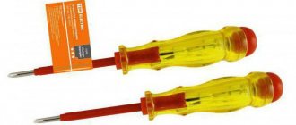
Indicator screwdriver
A more accurate method is to use an indicator screwdriver. It consists of a non-conductive housing and a built-in resistor with an indicator, which is an ordinary neon light bulb.
For example, when connecting a switch, the main thing is not to confuse zero with phase, since this switching device only works to break the phase. Checking with an indicator screwdriver is as follows:
- Turn off the common entrance machine for the apartment.
- Using a knife, strip the cores being tested from the insulating layer by 1 cm. Place them apart at a safe distance to completely eliminate the possibility of contact.
- Apply voltage by turning on the input circuit breaker.
- Use the tip of the screwdriver to touch the exposed conductors. If the indicator window lights up, it means the wire corresponds to the phase wire. The absence of a glow indicates that the wire found is zero.
- Mark the required core with a marker or a piece of electrical tape, then turn off the general circuit breaker again and connect the switching device.
More complex and accurate tests are performed using a multimeter.
Finding the phase using an indicator screwdriver and a multimeter in the video:
How to find which wire is phase
There is no special mode in a digital multimeter to understand exactly where the neutral or phase wire is. By connecting the probes in a certain way, the technician can search for wires based on the information displayed on the display.
Preparing for work
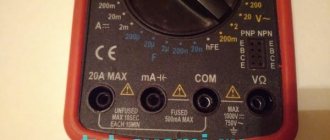
Before finding a phase in the socket with a multimeter, you need to set the operating mode of this device. To do this, the mode indicator is set to the position in which the AC voltage is measured.
Usually you have to choose from several modes. The scale indicates different AC voltage values. Since it is usually 220 volts at the outlet, you should choose the closest value that exceeds it, such as 500 V.
You need to connect the probes correctly. For black, the COM connector is used, and for red, the one next to it.
Checking the functionality of the device
In order to correctly determine the phase with a multimeter, you must first make sure that the measuring device is working. A convenient option for this may be to check the outlet. Using a prepared and configured device, you need to place both probes in the sockets of the socket. The display will show the actual AC voltage value.
Checking the voltage at the outlet
Maintaining polarity in this case when placing wires in sockets is not important. It is important to follow safety regulations during the measurement process. In this case, there should be no contact with those parts from which you could receive an electric shock.
Typically, real indicators are within the range of 215–235 V, but they can only be determined with a working device. Therefore, before checking the phase with a multimeter, you need to know for sure that it is working.
Multimeter. What kind of device is this?
A multimeter (electricians also call it a tester) is a combined device for electrical measurements that combines many functions, the main ones of which are ohmmeter, ammeter, and voltmeter.
These devices are different:
- analog;
- digital;
- portable lungs for some basic measurements;
- complex stationary with a large number of possibilities.
Using a multimeter, you can not only determine ground, zero or phase, but also measure current, voltage, resistance in a section of the circuit, and check the electrical circuit for integrity.
The device consists of a display (or screen) and a switch that can be set to different positions (there are eight sectors around it). At the very top (in the center) there is an “OFF” sector; when the switch is set to this position, it means the device is turned off. To perform voltage measurements, you will need to set the switch to the “ACV” (for alternating voltage) and “DCV” (for direct voltage) sectors.
The multimeter kit includes two more test leads - black and red. The black probe is connected to the lower socket marked “COM”; this connection is permanent and is used when carrying out any measurements. Depending on the measurements, the red probe is inserted into the middle or upper socket.
Methods for determining the working “phase” and “zero” using instruments
The conductor with the working “phase” has the same voltage as in the outlet: 220V. It is necessary for the functioning of household electrical appliances. In the neutral conductor the current voltage is very weak. Identification of wires is carried out by elimination method as soon as phase contact is detected.
There are several ways to determine the “phase”: by the color of the wires, by letter markings and using instruments - an indicator screwdriver and a multimeter.
Using a multimeter
A multimeter is a device that allows you to measure the basic characteristics of a network. In addition to other functions, it will not be difficult to determine the phase contact. This can be done anywhere - in an outlet, box, distribution board, etc.
To do this you need to do the following:
- set the regulator to the position that allows for measuring alternating voltage. In this case, the available range for the device is from 1 to 200 or up to 750 V. Since 220 V is supplied to the household consumer, you should select the second of the indicated positions (designation on the front panel ACV with the number 750);
- one probe is applied to the contact, the second is clamped with your fingers. The screen will display the voltage value, by the value of which it will not be difficult to determine the identity of this wire (from 0 to 15 V - zero, up to 230 - phase).
It is not necessary to pinch the second dipstick with your fingers. You can touch the wall near the outlet or a grounded contact.
Knowing the phase contact, it will not be difficult to distinguish the ground from the working zero. To do this, with the switch position indicated above, you need to place one probe on the phase wire, touching the other two in turn. On the ground, the voltage value displayed by the device will be higher.
Similar measurements can be performed with any household appliance. Even the cheapest models are quite suitable for these purposes. The accuracy of their measurement will be quite sufficient.
Tester
How to determine the phase using a tester:
- The multimeter is getting ready for use. The black test leads are connected to the COM jack and the red test leads are connected to the voltage jack.
- The operating mode switch is placed on the section designated for AC voltage measurements (~V or ACV) and the needle will be set to a value that is greater than the mains value. In another variation it could be, for example, 500, 600 or 750 volts.
- Next, the voltage is measured between the stripped conductors. In this case there can be three combinations. The first is that between phase and zero the voltage should be close to the standard voltage of 220 volts. The second is that there can be the same voltage between phase and ground. However, it is true that if the line is equipped with a current leakage protection system (residual current protective device - RCD), this protection can work properly. If there is no RCD or the leakage current is small, the voltage remains within the rated range. Third - there should be no voltage between zero and ground
This is only the last option to show that the wire that does not include the measurement is phase.
Important! After checking, the voltage must be turned off and the bare end of the wire must be insulated and marked.
For example, you can stick a white tape and write the appropriate inscription on it.
How to determine phase and zero with a multimeter or tester
Here, first of all, switch the tester to AC voltage measurement mode.
Next, measurement can be done in several ways:
- pinch one of the probes with two fingers. Connect the second probe to a contact in a socket or switch. If the readings on the multimeter display are insignificant (up to 10 Volts), this indicates that you have touched the neutral conductor.
- If you touch another contact, the readings will change. Depending on the quality of your device, this can be several tens of volts, as well as 100V and above. We conclude that there is a phase in this contact.
- If you are afraid to touch the dipstick with your hands in any case, you can try another way. You insert one rod into the socket, and with the other you simply touch the wall next to the socket. If you have plaster, the result will be similar with the first measurement.
- Another way is to use one of the probes to touch a known grounded surface (the body of a switchboard or equipment), and with the other to touch the wire being measured. If it is phase, the tester will show the presence of 220V voltage.
Safety precautions when working with a multimeter:
- Before determining the phase using the first method (when you hold the probe with your fingers), be sure to make sure that the multimeter is turned on to the “voltage measurement” position - the ~V or ACV icon. Otherwise you may get an electric shock.
- Some “experienced” electricians use a so-called test light to determine the phase. I do not recommend this method to ordinary users, especially since it is prohibited by the rules. Use only serviceable and tested measuring instruments.
We recommend reading: The gimlet rule for determining the direction of the magnetic field
Using an indicator screwdriver
This is perhaps the simplest and most accessible method. As already mentioned, the cost of the simplest device is very low. And learning to work with it takes just a few minutes.
So, how does a regular indicator screwdriver work:
The device of the simplest indicator screwdriver
The entire “filling” of this probe is assembled in a hollow body (item 1), made of dielectric material.
The working part of such a screwdriver is a metal blade (item 2), most often of a flat shape. To reduce the likelihood of accidental contact with other conductive parts located near the wire under test, the exposed tip of the tip is usually small. The sting may be short by itself, or “dressed” in an insulating sheath.
Important - the tip of the indicator screwdriver should be considered exactly as a contact tip when testing. Yes, if necessary, they can also perform simple installation operations, for example, unscrew the screw holding the cover of a socket or switch. But regularly using it as a screwdriver is a big mistake. And the device will not last long with such operation; it is simply not designed for high loads.
The metal rod of the tip, which enters the housing, becomes a conductor that provides contact with the internal circuit of the indicator. And the circuit itself consists, firstly, of a powerful resistor (item 4) with a nominal value of at least 500 kOhm. Its task is to reduce the current strength when closing the circuit to values that are safe for humans.
The next element is a neon light bulb (item 5), capable of lighting up with very small amounts of current flowing through it. Mutual electrical contact of all circuit elements is ensured by a pressure spring (item 6). And it, in turn, is compressed by a plug screwed into the end end of the body (item 7), which can be either completely metal or have a metal “heel”. That is, this plug plays the role of a contact pad during checks.
When you touch the contact pad with your finger, the user is “connected” to the circuit. The human body, firstly, itself has a certain conductivity, and secondly, it is a very large “capacitor”.
The principle of searching for phase and zero is based on this. The tip of the indicator screwdriver touches the stripped conductor (the terminal of a socket or switch, another thin-bearing part, for example, the contact blade of a light bulb socket). Then the contact pad of the probe is touched with a finger.
The check shows that the indicator screwdriver has touched the phase
If the tip of the screwdriver touches the phase, then when the circuit is closed, the voltage is enough to cause a current that is not dangerous to humans, causing the neon bulb to glow.
In the same case, if the test occurred on zero contact, no glow will occur. Yes, there is also a small potential there, especially if other electrical appliances are working in the apartment (house) at that time. But the current, thanks to the resistor, will be so small that it should not cause the indicator to light up.
The same is true on the grounding conductor - in fact, there should be no potential there at all.
In the same case, if, say, two contacts in a socket show phase, this is a reason to look for the cause of such a serious malfunction. But this is a topic for separate consideration.
The check is performed somewhat differently with a more advanced type of indicator screwdriver. Such probes allow you not only to determine phase and zero, but also to carry out continuity testing of circuits and a number of other operations.
Externally, such indicator screwdrivers are very similar to the simplest ones discussed above. The only difference is that instead of a neon bulb, an LED is used. And the case contains 3-volt power supplies that ensure the functioning of the circuit.
A small addition to the circuit expands the functionality of indicator screwdrivers
If you are not sure which specific screwdriver the user has at his disposal, you can conduct a simple test. They simply touch both the tip and the contact pad with their hand at the same time. At the same time, the circuit will be closed, and the LED will signal this with its glow.
A simple test showing which indicator screwdriver is available to the DIYer. If the indicator lights up (top fragment), then this is a screwdriver with built-in power and a ringing function. If not, it's normal.
Why is all this being said? Yes, simply because the algorithm for determining phase and zero when using such a screwdriver changes somewhat. Specifically, you don’t need to touch the contact pad. Simply touching the phase conductor will cause the indicator to light up. There will be no such glow at the working zero and at grounding.
Nowadays, more expensive indicator screwdrivers with electronic filling, light and sound indication are also widely available on sale. And often even with a digital liquid crystal display showing the voltage on the conductor being tested. That is, in essence, the indicator screwdriver becomes a simplified version of a multimeter.
Electronic indicator screwdrivers: on the left - with light and sound indication, on the right - also with a digital display
Using these is also not particularly difficult. You will have to follow the instructions supplied with the device - in any case, the device must clearly indicate the presence of voltage on the phase wire and the absence of voltage on the neutral or ground wire. The main thing is to make sure before starting the test that the capabilities of the device used correspond to the network voltage. This is usually indicated directly on the indicator body.
Another “relative” of indicator screwdrivers is the non-contact voltage tester. There are no conductive parts at all on its body. And the working part is an elongated plastic “spout”, which is connected to the conductor under test (terminal).
Non-contact voltage indicator - able to “feel” the phase even through insulation.
The convenience of such a device is also that it is not at all necessary to strip the insulation from the wire being tested. The device reacts not to contact, but to the electromagnetic alternating field created by the conductor. At a certain voltage, the circuit is triggered, and the device signals that there is a phase wire in front of us by turning on a light and sound signal.
We recommend reading: Marking wires and cables: deciphering the factory markings on the insulation
Safety precautions when working with the “probe”
- never touch the bottom of the screwdriver when taking measurements
- The screwdriver must be clean before measurement, otherwise insulation breakdown may occur
- If you need to use an indicator screwdriver to determine the absence of voltage, rather than its presence, in order to safely work with the wiring, first check the operation of the device on equipment that is known to be energized.
How to use the device?
Above, we looked at how to find a phase wire using an indicator screwdriver, but it will not be possible to distinguish between zero and ground using such a tool. Then let's learn how to test the wires with a multimeter.
The preparatory stage looks exactly the same as for working with an indicator screwdriver. When the voltage is turned off, strip the ends of the wires and be sure to separate them so as not to provoke accidental contact and a short circuit. Apply voltage, now all further work will be with a multimeter:
- Select on the device the measuring limit of alternating voltage above 220 V. As a rule, there is a mark with a value of 750 V in the “ACV” mode, set the switch to this position.
- The device has three sockets into which test leads are inserted. Let's find among them the one marked with the letter “V” (that is, for measuring voltage). Insert the dipstick into it.
- Touch the probe to the stripped conductors and look at the device screen. If you see a small voltage value (up to 20 V), it means you are touching a phase wire. In the case where there is no reading on the screen, you found zero with a multimeter.
To determine the “ground”, clean a small area on any metal element of home communications (this could be water or heating pipes, radiators).
In this case, we will use two sockets “COM” and “V”, insert the measuring probes into them. Set the device to “ACV” mode, at a value of 200 V.
We have three wires, among them we need to find phase, zero and ground. Touch the stripped area on the pipe or battery with one probe, and touch the conductor with the other. If the screen displays a reading of about 150-220 V, it means you have found a phase wire. For the neutral wire, with similar measurements, the reading fluctuates between 5-10 V; when you touch the ground, nothing will be displayed on the screen.
Mark each core with a marker or electrical tape, and to make sure the measurements taken are correct, now take measurements relative to each other.
Touch the phase and neutral conductors with two probes, a figure within 220 V should appear on the screen. The phase and ground will give a slightly lower reading. And if you touch zero and ground, the screen will show a value from 1 to 10 V.
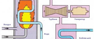
Features of the supply of electricity to a house or apartment
Voltage is supplied to the network through wires coming from the nearest substation. The consumer receives three-phase or single-phase voltage, and it is in this form that electricity enters the home.
If the house has three-phase voltage, it can be used for 220 or 380 V outlets. The latter option is intended for high-power equipment. When single-phase voltage is supplied, 220 V sockets are used in the house.
The neutral wire connects the site with the house to the transformer substation. On it it is connected to ground. Most sockets have a phase and neutral connection. Some modern sockets additionally provide a ground. There are devices for which the presence of such an output is mandatory.
The use of grounding protects a person from electric shock in the event of a breakdown on the metal body of the device. When accessing the ground, the charge drains from the device without causing harm to a person.
Thus, the cable can contain up to five wires: three phase, neutral and ground. However, it is often used with only two - phase and neutral. Each of these wires has its own color, which is how they are found. For zero, shades of cyan or blue are usually used, for grounding - mainly green or yellow. The wires used for the phase can be white, black or brown, sometimes gray. But it should be noted that this sign cannot be considered sufficiently reliable. It can only be considered as additional. You also need to check the purpose of the wires using a tester.
A few rules for using a multimeter
Before determining phase and zero with a multimeter, familiarize yourself with several rules that must be followed when working with the device:
- Never use the multimeter in a damp environment.
- Do not use faulty test leads.
- While taking measurements, do not change the measuring limits and do not rearrange the switch position.
- Do not measure parameters whose value is higher than the upper measuring limit of the device.
How to measure voltage with a multimeter - in the following video:
Pay attention to an important nuance in using a multimeter. The rotary switch should always be initially set to the maximum position to avoid damage to the electronic device. And in the future, if the readings are lower, the switch is moved to lower levels to obtain the most accurate measurements.
Checking the three-wire connection
When installing lighting devices, three wires are often used for installation: those related to phase and neutral, as well as grounding. If you compare zero and ground, zero voltage will be found between them.
By determining the phase, you can see that the voltage between the loaded wire and zero is 220 V. If you check the phase wire and ground, the result will be the same. The sequence of connecting the red and black probes to phase and zero during these measurements does not affect anything.
Prohibited and dangerous methods
The accuracy of conductor identification directly affects the safety of using household devices. Therefore, the phase search method must be reliable. There are traditional methods for determining the phase conductor that are prohibited from being used. These include creating a homemade system with an incandescent lamp. You may receive an electric shock during operation.
Some people look for the phase in a three-wire and two-wire wire using a potato. This is also a method that is not reliable and is unsafe. It will not be possible to find out exactly the purpose of the cores.
Control potato
The most unusual method of determining the phase will require 2 wires and potatoes. 2 conductors are inserted into a tuber cut in half at the maximum distance from each other. One is placed over something grounded (a heating system pipe), the other is placed over the contact being tested. After 5-10 minutes, inspect the potato cut. If a spot appears on it, then the conductor being tested is a “phase”. If there is no spot - “zero”.
Using water
To determine the polarity of the contacts, using a similar method, lower two wires into a container of water. If bubbles form around one, this is a minus. Therefore, the second core is a plus.
This method is also dangerous; precautions must be taken when using it.
When using available means to identify a live wire, you must be extremely careful. If safety precautions are not followed, you may receive an electric shock.