Every home has electrical appliances and wiring, the operation of which poses some difficulties. Calling a professional electrician for every slightest problem will cost a pretty penny; it is much easier to solve the problem yourself. For these purposes, you may need a multimeter that measures network parameters. However, the tool is expensive, and purchasing it is not always advisable for use at home. Its functions can be replaced by an indicator screwdriver. What is it and how to use it? How to determine where the phase is and where the zero is?
Principle of operation
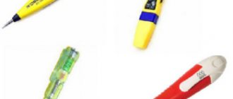
How does an indicator screwdriver work? The appearance of the device is similar to an ordinary screwdriver, but it has an indicator built into the cavity of the handle. The metal part of the screwdriver acts as a probe, and it is capable of reducing the power of the supplied electricity so that using the device is as safe as possible. The device also has an LED, which is located at the top of the handle. In addition, the screwdriver has a contact-type metal plate.
The principle of operation is quite simple - the screwdriver probe touches the electrical conductor, then, passing through it, the current strength decreases significantly, after which the person touches the contact plate with his finger. The circuit closes, causing the light to light up. A screwdriver is necessary to indicate the presence of direct or alternating current in the network.
Zero is missing from the socket. Is it possible to extend the wire from the neighboring one?
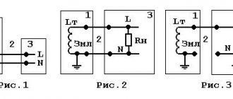
The headache of any electrician is the loss of zero. In its absence, all consumers will be without electricity. The neutral wire appears from the midpoint of the windings of a high-voltage transformer connected in a star. This point is routed to all cabinets and panels, and the grounding bus also extends from this point. The neutral wire is most important for the safety of electrical equipment.
The alternating voltage in the network has a sinusoidal shape. The three phases are shifted relative to each other by an angle of 120*. This is a bit confusing, so these curves are illustrated here. If you measure the voltage with a standard voltmeter, this value between the phase wire and the neutral wire will be 220 V, but this is the average value for half the period. The tester is not an oscilloscope, but only an average meter. In fact, the instantaneous values of peak voltages are greater than 220 V to the square root of 2. In other words, 220 * 2^0.5 = 311 V.
The voltage sine wave says that the average voltage value is 220 V, the peak value is 311 V. Measurements are taken relative to the zero abscissa axis.
The shape of the curve between the two phases is also a sinusoid. The average line voltage is 380 V, and the peak voltage is 536 V.
From the point of view of the average person, it is not clear why when zero is lost, the voltage in the network should increase. Logic dictates exactly the opposite - a complete loss of voltage. And indeed, if you disconnect the neutral wire to your apartment, the light will go out and nothing bad will happen to the equipment. But here we are talking about a zero break at a substation or at floor-to-floor distribution boards.
Let's start unwinding the ball from the very beginning - the active energy meter. At first glance, this is a standard device, but there is a pitfall here. The meter has two windings - voltage, connected between phase and zero, and current, included in the phase break. The voltage between points A and B is 220 V, completely dropping across the voltage winding.
If the zero is broken, the phase will flow through the voltage winding and flow to the consumer. If a consumer takes the indicator and pokes it into a socket, he will detect two phases at once, but the voltmeter will show a stable zero. Perhaps this information will make many people’s brains boil, but there is nothing magical here. It's all about the counter.
If the phase breaks, everything is more logical - nothing will be observed anywhere.
Now about the main thing. When the zero drops to the meters that supply two or more apartments, an interesting process occurs.
Determination of zero and phase
Many novice electricians and people who decide to repair electrical appliances on their own are interested in how to find phase and zero with an indicator screwdriver. To do this, you should adhere to the following operating algorithm:
- first the wiring is de-energized;
- the wires that need to be tested must be stripped of the insulating winding;
- after which you need to turn on the electricity;
- Use the probe to touch the wires one by one, while remembering that the circuit must be closed with a finger on the contact plate;
- the wire that, when touched, lights up the light bulb, is a phase of the electrical circuit.
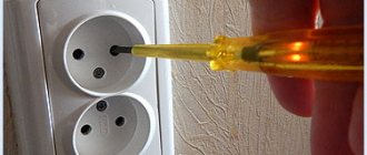
How to find phase and zero with an indicator screwdriver in a socket? To do this, you need to place the probe one by one in the holes of the socket. When a phase is detected, the light will light up. There will be no glow if the screwdriver shows zero. If, when touching both holes of the socket, the light bulb does not light up, this indicates a break in the zero.
In addition to using an indicator screwdriver, you can determine the phase by the color of the wire:
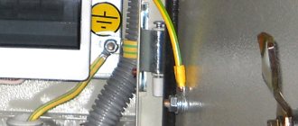
- the yellow-green wire is ground;
- phase wire color - black;
- zero has a blue wire color.
If the color distribution is not observed, you will need an indicator screwdriver to determine.
Application of the warning lamp
The test lamp is a simple incandescent lamp to which two insulated wires of a few centimeters each are attached. One end of the wire should be touched to the heating radiator or pipeline, and the other to the area being tested. Let's see how to determine the phase. It is located where the light came on during this procedure. It is necessary to understand that this method is quite dangerous due to the high probability of electric shock.
Many people think that it is easy to find a phase without special devices. But in fact, using improvised means is dangerous; with them you can easily lose your life. You definitely need to use equipment – even if it’s a simple one. It is enough to purchase the simplest power indicator, which is not at all expensive.
Checking the serviceability of incandescent lamps
When purchasing another incandescent light bulb, it is important to check its performance right in the store. If there is no appropriate stand, this can be done using an ordinary indicator screwdriver. To do this, you need to take the lamp with one hand by the metal base, and with the probe of the indicator screwdriver in the other hand, touch the central contact on the lamp. If it is working properly, the LED on the device will light up.
Despite the fact that the method is effective, the result may be a failure if the light bulb is depressurized. In this case, the electrical circuit is maintained, but the lamp still will not light up. However, this happens quite rarely.
Features of home electrical networks
In almost all apartments, electricity is supplied through a single-phase network, with a voltage of 220 volts and a frequency of 50 Hz. General power is supplied to a residential building through a powerful three-phase line, and then the electricity is switched in distribution boards. Further movement of current to consumers is carried out through single-phase lines with phase and neutral wires.
The load distribution on each phase should be as uniform as possible to avoid distortions during operation. In modern houses, a protective grounding circuit is additionally laid. Thus, another wire is added to the electrical network, which will also have to be identified in the future if necessary.
In the private sector, three-phase lines are often used. A voltage of 380 volts can be directly supplied to individual consumers - heating boilers, electric motors and other equipment. However, for internal wiring inside a private house, single-phase lines are still used, in which all three phases are evenly distributed. Thus, three wires are connected to the sockets - phase, neutral and ground.
Checking the heating element
You can check the functionality of the heating element of the washing machine without even removing it. It is enough to provide access to the contacts; the remaining wires must be disconnected. To check, you need to touch one of the contacts of the heating element with your hand, and the probe of a screwdriver to the other. In this case, the circuit is closed by touching the metal plate on the device. If the lamp lights up, then the heating element is working.
Alternative methods without the use of instruments
If the situation is such that there is neither an indicator screwdriver nor a multimeter, but it is necessary to find out which contact is phase, use a visual method for determining the contact.
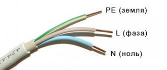
On the cable there is often a letter designation of the characteristics of the conductors. So, the letter L is assigned to the “phase”, N to the “zero”, and PE to the “earth”.
Sometimes electricians during installation additionally mark the phase wire with a hanging tag with a designation. But a simpler solution is color coding of wires. Connecting them correctly (in accordance with the standard) subsequently makes the work of electricians easier, allowing them to quickly navigate the wiring.
By wire color
The colors of the wire insulation are selected so that they differ as much as possible from each other:
- The "phase" is often white, black or brown.
- “Zero” - blue and its shades.
- "Earth" - yellow-green.
But the standards for connecting conductors are not always observed. Therefore, for the sake of safety, it is better to check the voltage in the wires, regardless of their visual markings.
Wire marking standard
Using a control lamp
This method is considered the most risky, but it helps out in situations where the usual testers are not at hand. The inspector needs a lamp twisted into a socket from which 2 wires come out. To safely use such a “device,” it is better to attach probes to the ends of the wires and wrap the lamp itself with a protective casing.
You need to touch the metal pipe (or other grounding element) with one lamp tap, and check the contact with the other. If the lamp lights up, then the contact being diagnosed is “phase”.
Conductors can also be identified by exclusion:
- Alternately touch the lamp taps to two of the three contacts that need to be identified. If the lamp is on, it means that the “phase” - “zero” pair is engaged at this moment.
- To determine the phase and neutral conductors, one of the tester taps is used to touch the next of the three contacts being tested. The light goes out when disconnected from the “phase”. But this will only happen if a circuit breaker is installed in the network. If it is absent, the indicator lights up even in the “ground” - “zero” position.
- To identify the “ground”, if a circuit breaker is not installed, remove the ground from the cable and repeat the test. Now the lamp will not light on this conductor.
Assembling a control light at home is not difficult. To do this, you will need 2 conductors connected to the socket, and the light bulb itself screwed into it.
For safety reasons, it is better to use a neon lamp, and electricians recommend attaching probes to the wires - this will secure and facilitate the operation of the “control”.
Since the light bulb method is unsafe, it is best to avoid it.
Control potato
The most unusual method of determining the phase will require 2 wires and potatoes. 2 conductors are inserted into a tuber cut in half at the maximum distance from each other. One is placed over something grounded (a heating system pipe), the other is placed over the contact being tested. After 5-10 minutes, inspect the potato cut. If a spot appears on it, then the conductor being tested is a “phase”. If there is no spot - “zero”.
Checking the voltage in an insulated wire
How does an indicator screwdriver work? Its functionality allows you not only to determine phase and zero, but also to check the voltage in insulated wires. It is not recommended to cut through an unknown wire, as it is often unclear whether it is live or not. In this case, the following manipulations are carried out:
- You need to take the indicator screwdriver directly by the dipstick;
- the metal plate must be attached to the wire;
- if the cable is live, the indicator on the screwdriver will show this.
This method of detection is suitable even for wires that are located under plaster, however, the glow may be less bright.
How to find phase with a multimeter
To determine the phase using a multimeter, we set it to the AC voltage detection mode, which is most often indicated on the tester body as V~, and always select the measurement limit - a setting higher than the expected network voltage, usually from 500 to 800 Volts. The probes are connected as standard: black into the “COM” connector, red into the “VΩmA” connector.
First of all, before looking for a phase with a multimeter, you need to check its performance, namely the operation of the voltmeter mode - determining the alternating current voltage. To do this, the easiest way is to try to determine the voltage in a standard 220V household outlet.
Finding a broken wire
The instructions for the indicator screwdriver note the versatility of the device. This is very important and convenient for home use. Having figured out how to find phase and zero with an indicator screwdriver, you can also use it to find a broken wire. If the carrier suddenly stops working, then the first thing you need to do is check the integrity of the electrical circuit:
- You need to make sure that there is no short circuit - to do this, you need to free the carrier from the devices included in it, grab one contact of the plug with your hand, and touch the other with a probe. If there is no light, then there is no short circuit.
- To find a damaged wire, you need to pinch one of the plug contacts with your fingers. Use the probe of the screwdriver to touch the sockets of the extension cord one by one. In which of the sockets there is no glow, a break is observed.
- It needs to be marked with a marker. Then you need to find out the location - where is the phase and where is the zero; once this is done, the plug must be inserted into the socket so that these indicators coincide.
- After that, the metal plate of the indicator screwdriver is used to search for a break. At this point the LED should go out.
The search for a broken wire in the wiring of the house is carried out in a similar way.
A light bulb will help you
If all the previous methods do not work, you can try to make a control light yourself. To do this, you need to find a regular incandescent lamp, a socket and two stranded wires, half a meter each.
The cores should be connected to the cartridge connectors. Next, one wire is attached to a piece of metal, and the conductors are tested with the second. If the light comes on, it means there is a phase ahead of you.
This method of determining zero is dangerous. Due to the large number of exposed wires, there is a high risk of electric shock. This method should be used only when absolutely necessary.
Electronic indicator screwdriver
You can find phase and zero using either an indicator screwdriver with an LED or an electronic one. The only differences are in their design. The electronic indicator screwdriver can be either with or without a liquid crystal screen.
Instead of a light signal, such a device notifies you of the presence of voltage with an audible signal. In addition, the great advantage of such a device is the display of voltage information on the LCD screen, if available. The operating principle of the electronic device is the same as that of a conventional indicator screwdriver.
With and without zero
Switch marking without zero: L, L1
Marking of the switch “with zero” - N, L, L1
Switch connection diagrams: with and without neutral wire
And now we come to the most important thing: what is the difference between these two types of switches?
- A switch “without zero”
is the most common switch that has been installed in every home for more than a hundred years. Only 2 wires go to it, the first of which is always the “phase” input (don’t forget!), and the second goes to the lamp. - The "zero" switch
is a relative innovation. In terms of connection logic, it is more like a socket into which you insert a lamp. The box with such a switch contains at least 3 wires: “zero” (for powering the switch itself), “phase”, and the third – the “phase” output to the lamp. If the switch is double or triple, then there are 1 or 2 more wires.
Smart switches are usually powered using the “zero” circuit (so that their electronic components work); according to the “no zero” scheme - ordinary “stupid” switches, or battery-powered switches. But more and more often, smart switches powered by the network are also found according to the “zero-free” scheme. How do they work? After all, current can only pass if there is a potential difference and in the presence of a closed circuit? The highlight of the circuit is that a special small part (“shunt”) is connected in parallel with the lamp, which ensures the passage of a tiny, but sufficient current for the operation of such a switch.
There are switches without a shunt, for example, from Aqara.
Functionality check
Before you determine where the phase is and where the zero is, you need to check the functionality of the screwdriver itself, since it, like any other device, can be faulty. To do this, you should pay attention to the following nuances:
- The device body must maintain its integrity. Working with electricity requires good insulation without damage.
- For accuracy of readings, you should check the screwdriver. To do this, touch the conductor with the probe, which is 100% energized.
- If you use a battery-powered product, you need to replace them promptly.
Safety when using a screwdriver is extremely important, therefore, if a malfunction is detected, it is recommended to purchase a new device. The cost varies from 50 to 1000 rubles. depending on modification.
Determining the purpose of wires by color
Insulation of power conductor, grounding, etc. painted in certain colors. According to the European Union Standard IEC 60445 of 2010, power supply wires must be painted brown, black, or gray. Blue insulation indicates conductors with zero. Grounding is painted in a two-color green-yellow winding. In addition, the Standard prohibits the use of grounding only in yellow or only in green. In Russia, GOST 50462 of 2009 is widespread, which almost fully complies with the European Standard and according to which coloring is carried out in the same way. It is necessary to pay attention to the fact that it is not the best solution to search for the presence of voltage only by color marking, since electricians may make connections differently.
Security measures
When working with the device, the following safety precautions must be observed:
- The screwdriver should not be disassembled; only the batteries, if any, should be replaced.
- The use of a damaged screwdriver is strictly prohibited.
- Do not use the device without a screw.
- When the probe comes into contact with electricity, do not touch the exposed part of the device with your hands.
- Do not use the device at voltages higher than those indicated in the technical specifications.
In order to find out whether phase or zero is lit on the indicator screwdriver, you need to follow all the recommendations outlined above. At the same time, it is important to monitor the serviceability of the device and not neglect the rules for the safe use of an indicator screwdriver.
Determination of phase and neutral wires
The easiest way to understand the purpose of the wires is to focus on the markings. In the Russian Federation and a number of European countries the following standard applies:
- zero, or neutral (working zero) - a wire of blue, less often blue-white color
- earth (grounding, protective zero) – yellow-green;
- phase - any other color, often brown, black.
But color markings may be missing or may not correspond to the standard. In this case, use an indicator screwdriver (probe) or a tester.
Testing with a probe:
- Hold the screwdriver body in your hand without touching the metal tip with your fingers.
- Place your index finger on the end of the screwdriver where there is metal contact.
- Touch the wires one by one; the LED indicator lights up when in contact with a phase wire.
If there are only 2 wires in front of you, and you have figured out where the phase is in the wiring, the problem is solved. If there are 3 of them, you need to distinguish the working zero from the protective zero, that is, grounding. To do this you will need a tester (multimeter). The phase wire is marked with a marker. On the multimeter, you need to select the alternating current measurement mode and set the measurement limit to exceed 250 V. One probe is pressed against the phase conductor, and the other two touch the other two in turn. The display will show the voltage value. When measuring the voltage between phase and ground, this indicator is greater, between phase and neutral it is less.
Sometimes both measurements give the same result. In this case, you can check where the ground is by measuring the resistance. The stripped phase wire core must first be insulated. The device switches to resistance measurement mode; one probe is touched to an object that is precisely grounded, for example, a metal pipe, a heating radiator or a water tap. By touching the second probe alternately to two wires, measure the resistance. Between a grounded object and the ground wire, the resistance is within 4 ohms; when checking the neutral wire, it is higher.
If you don’t have an indicator screwdriver, a multimeter will help you figure out which wire is which in the wiring. Having selected the alternating current measurement mode, touch the grounded object with one probe and check the wires with the second. The device will show the following voltage values between the grounded pipe and the wires:
- phase 150-220 V;
- zero (neutral) – 5-10 V;
- ground – 0 V.
Electrician's recommendations
Non-contact screwdrivers are very sensitive, it can react to both phase and neutral, although the real voltage will only be in one wire. Therefore, an ordinary electrician does not need such a screwdriver. However, it can help in checking the quality of cable shielding and the absence of radiation.
In such devices there are three switch positions. Two are provided for remote operation. If you accidentally touch the current-carrying part of the wire with a screwdriver in this mode, the entire electronic part, consisting of transistors and an LED, will burn out.
Electrical appliances surround people in everyday life. Sooner or later, problems and malfunctions arise in any electrical system. These problems are not always worth calling in an experienced electrician; some breakdowns can be fixed on your own. However, to be able to find a fault in the network you will definitely need a special tool, which is worth purchasing in advance.