The indicator screwdriver, despite its simplicity, is a functional tool. It is used with equal success by professional electricians and people far from this field. Using the device, they determine the polarity of the battery, find a breakdown of electrical wiring in the wall, check the voltage on a hidden cable, determine the phase and neutral wires at the connection point of a key switch, household appliances, and eliminate the risk of overheating and failure of equipment from improper installation.
Types and design of indicator screwdrivers
The tester includes a metal tip that acts as a conductor and a resistor that converts electricity to a safe value. The indicating element in the electrical circuit of a screwdriver is a neon light bulb or LED, which is installed after the resistor. The indicator is connected to a conductive contact on the end or body of the handle.
The operating principle of the probe is simple. The tip of the device is applied to the wire, the current, if it is a phase, passes through the tester, a resistor (resistance) to a lamp or diode, and then to the ground. When working with the device, a person acts as a grounding element. When current passes through the resistor, its value drops to safe values, the user does not feel when the current passes through the body.
This design is the basis for the simplest and most universal tester models. There are several types of indicator screwdrivers:
Simple
A working electrical circuit is installed in the case, with a standard set of elements: transistor, resistor, indicator - neon bulbs. The zero phase is the person who closes the contact plate. The tool is not functional - it detects the voltage on the wire, but often does not work when the network voltage is less than 60 Volts. Not suitable for searching for network breaks.
With LEDs
The models have design and functional differences from the primitive model. An LED is installed as an indicator, allowing you to check the circuit at a voltage not exceeding 60 Volts. Probes of this type contain a bipolar transistor and batteries, which make it possible to perform contactless testing. LED probes are suitable for determining breaks in an electrical circuit and testing electrical equipment circuits.
Universal
Portable devices with a wide range of capabilities. An instrument of this type performs contact and non-contact testing, determines open circuits and short circuits using “ringing” of networks, and light and sound warnings help with this. Universal probes are used when repairing or setting up electronic devices and vehicles; they are designed to work with direct and alternating current. The tester operates on a battery, the charge of which is monitored. If the battery loses charge, the universal screwdriver will not work.
The type of indicator screwdriver is selected depending on the intended work. For everyday use, a simple model is sufficient, but for working with electronic devices, choose a universal device.
Tools
0 votes
+
Vote for!
—
Vote against!
At times, there is a problem with the electrical wiring and electrical appliances in the house. It is not always convenient to call a specialist in every case (waiting time, payment for services), and it is not always advisable. Most problems can be easily fixed yourself in a matter of minutes. For example, if contact is lost in a socket or switch. But to do this, you need to find the problem area and fix the problem. How can you find it if the electric current is invisible and dangerous? And the conductor is either hidden in the wall or in insulating material.
This means that for these purposes, we need a reliable and inexpensive device (an expensive one for simple work with electrical circuits is simply unnecessary), which would allow us to “see” where there is voltage and where there is not. This versatile and affordable device is an indicator screwdriver. This will be discussed in this article.
Content
- Types and principle of operation of an indicator screwdriver
- Methods of application
- Models and their abilities
- How to check the indicator screwdriver?
Types and principle of operation of an indicator screwdriver
To successfully use any device, you need to understand what its operating principle is based on. The same is true for the indicator screwdriver. Knowing how it works and works, at least in general terms, will allow you to use it effectively and eliminate mistakes. In addition, this will allow you to do without a more complex and expensive multimeter.
Let's look at several main types of indicator screwdrivers; this will allow us to choose a more suitable option in the future.
A regular voltage tester with a neon lamp. The operating principle of the indicator screwdriver is as follows. Electric current from the surface of the conductor reaches the tip of the screwdriver, then through a resistor with a nominal value of at least 0.5 mOhm (limiting the current) it reaches the contact of the neon lamp. The second contact of the light bulb switching circuit is closed to the person through the contact on the screwdriver handle. With this type of screwdriver, the capacitance and resistance of the human body are included in the light bulb circuit. That is, if you touch the wire with a sting and touch the contact with your finger, if there is voltage, we see the glow of a neon light bulb. There is no contact with a person - the lamp does not light. The disadvantage of this type of screwdriver is the high voltage indication threshold, from 60V. They are only good for determining the presence of voltage and phase. It is impossible to determine an open circuit using this tool.
Screwdrivers with LED indicator. The operating principle is similar to a screwdriver with a neon lamp. The main difference is a lower voltage indication threshold; the LED will glow at a voltage less than 60V.
Screwdrivers with LED indicator and autonomous power supply (batteries). This is already a multifunctional indicator screwdriver. In addition to the power source, such a screwdriver also includes a transistor, usually bipolar. It has five functions:
- phase determinant;
- determine open circuit;
- allows you to find the location of damage in the conductor;
- determine the polarity of direct current sources;
- Using the ability to determine the presence of voltage in a non-contact manner, you can find the location of the wiring (this effect is based on inducing the magnitude of the magnetic field).
Some versions of these screwdrivers can also detect microwave radiation, such as those found in microwave ovens.
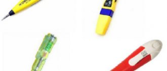
Electronic indicator screwdriver. Available in two versions: with or without LCD display. Equipped with audible voltage alarm. In fact, this is a simplified and very convenient multimeter. The LCD display allows you to not only determine the presence of voltage, but also its magnitude (from 12V to 220V). The principle of operation is generally similar to previous analogues of indicator screwdrivers. We will not give the actual diagram of such a device; it is unlikely that if such a screwdriver breaks down, you will look for faulty elements on the radio market and replace them. The time spent on repairing it simply will not be worth the cost of a new tool.
Methods of application
Having looked at the types, let's get acquainted with how to properly use an indicator screwdriver. First of all, you need to remember the safety rules when working with electrical networks. The basic rule is that all installation and repair work in electrical circuits must be carried out with the package switches turned off, which are installed at the points of entry into the home. Do not disassemble the socket, carrying case or table lamp if there is voltage in the network of the apartment or house.
It is also necessary to understand the principle of electrical wiring and the devices that consume it. Basic rule: electric current always flows through a conductor along the path of least resistance, from plus to minus. Any electrical appliance works only when the plus or phase through the electrical circuit of this device reaches the negative or neutral wire of the network. And nothing else. If this circuit is broken or blocked (by a transistor, diode, etc.), the device will not work. An indicator screwdriver is of little use for electronics and complex electrical appliances. But for checking the serviceability of the circuit to these devices, it is an extremely convenient thing.
According to accepted standards, our homes use networks with a voltage of 220V and a frequency of 50Hz. The network is single-phase, i.e. voltage always comes through one wire - it is called phase (+). The second wire is zero, the return wire leading to the transformer (-). The presence of a third wire in the socket is grounding. Does not affect the operation of electrical appliances. This wire serves for our safety; the voltage, once on the metal body of the device, will go into the ground and will not “hit” us.
Whenever repairing electrical wiring, you must make sure that there is no phase. We remember two wires, one phase - it beats and zero - it doesn’t beat. In order to determine “which of them is which” you need an indicator screwdriver. We insert it into the socket or touch the conductor; if it lights up, it’s phase, if it doesn’t, it’s zero. This is important when connecting lighting fixtures and switches to them. The switch must receive a phase, and the central contact of the lamp socket must also receive a positive phase.
In order to check switched-on electrical appliances for phase breakdown on the housing, simply touch any socket if it has connected grounding contacts. Those that protrude from the edges of the socket. If the light is on or we hear a beep, one of the devices is breaking through to the housing. To identify such a device, it is enough to turn them off one by one and turn off the mains, while constantly checking the ground contact for the presence of voltage. When the indicator goes out, the device in which there is a voltage leak has been found.
These types of work are available with ordinary screwdrivers. If we have an indicator screwdriver with batteries, then we can do much more. So, to determine the integrity of the lamp, it is enough to hold the base with one hand, and touch the tip of the screwdriver with the other, and place the tip on the central contact of the lamp. If the indicator lights up/beeps, the lamp is intact.
The wire is checked for breaks in the same way. We take one stripped end of the wire in our hand or by one of the contacts of the plug, and touch the second with the tip of a screwdriver. If the wire is intact, the screwdriver will light up, if there is a break, there will be no reaction. Of course, the conductor must be voltage-free! By the way, checking the wire through the plug is only possible in electrical appliances and only when the switch is on, otherwise the circuit will be open. It is impossible to check the extension cord this way.
To check the functionality of the extension cord using an indicator screwdriver, we need to disconnect it from the network and from electrical appliances. Take a piece of wire and strip the ends. We insert the extension cord into any socket so that the contacts are short-circuited. We take the plug and hold one contact with our hand, and touch the second with a screwdriver. If the extension cord chain is working properly, the screwdriver will light up. Don't forget to pick up the jumper - otherwise you will short-circuit the wiring when plugged into the network.
If it doesn’t light up, connect the extension cord to the network, take the screwdriver by the tip and slowly move the screwdriver handle along the wire. The place where the screwdriver stops shining or loses the intensity of the indication is the place of damage. We disconnect the extension cord from the network, take wire cutters, remove the insulation at the damage site, find the break and twist the wires. We isolate and use further. Or we buy a new extension cord, as you like.
To locate wiring in a wall, the procedure is similar. We hold the screwdriver in our hand by the tip and run it along the wall - where the wiring glows brightest, because... the indicator reacts to the electromagnetic field created by the current in the conductor. The disadvantage of this method of finding hidden wiring is its low accuracy. But in panel houses it is generally a hopeless matter, since the reinforcement in the slabs will create its own magnetic field.
As you can see, the scope of application of such a tool is quite wide; all cases of application cannot be counted. You can even check if the diode is broken.
Models and their abilities
In this part of the article we will present some of the most successful models and consider their characteristics.
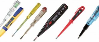
We will start with the SVETOZAR MS-48S SV-45203-48 model. The model has a convenient design and is equipped with light and sound voltage indication. The adjustable sensitivity of the “probe” allows you to more accurately determine the location of damage or hidden wiring. Although the latter still has a noticeable error. The cost of such a tool is within 3 -4 USD.
Indicator screwdriver Energy 6878-28NS. All available functions are available, the voltage values displayed on the display are 12V, 36V, 55V, 110V and 220V. The highlight of this device is the absence of batteries, while all functions are available. The cost is just over a dollar.
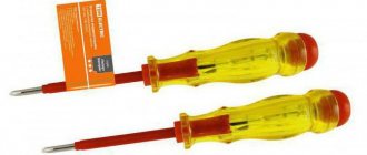
SafeLine multifunction indicator screwdriver MS-18. Five functions are available, cost 1.5 - 2.00.
And, of course, the “classic” Visting indicator screwdriver in the photo below. Simple and reliable, and the price is 0.5 USD.
In fact, the choice of indicator screwdrivers is huge, the price range is very wide from 0.3 to 15 -20 USD. per copy. Knowing your needs and capabilities, you can easily choose the best option for yourself.
How to check the indicator screwdriver?
Since the indicator screwdriver is designed to work with voltage, it is very important to constantly monitor its working condition. The body must be intact, without cracks. Each time before starting work, make sure that it is working properly. Check the serviceability by touching the conductor that has voltage. If the screwdriver has a power source, touch the tip and the spot on the handle - it should glow.
If the case is damaged, replace the screwdriver; your safety is much more valuable than its cost. Screwdrivers with batteries require periodic replacement. The procedure is quite simple, unscrew the cap, take out the old batteries and insert new ones. The main thing is not to confuse the polarity of the batteries - it will not work. When removing the “filling”, remember the sequence of arrangement of the elements, then the screwdriver will serve for many years.
If a breakdown occurs in the screwdriver itself, there is no point in repairing it. The price of a new one is not worth the time spent. True, if you have several identical faulty screwdrivers, then you can try to add one functional one.
And always be careful when working with electrical networks and devices. It is better to slowly recheck the measurement result several times than to receive an electric shock.
Where can I buy
To purchase a screwdriver as quickly as possible, you can visit your nearest specialty store. The optimal option, in terms of price-quality ratio, remains purchasing from the AliExpress online store. Mandatory long waits for parcels from China are a thing of the past, because now many goods are in intermediate warehouses in destination countries: for example, when ordering, you can select the “Delivery from the Russian Federation” option:
| 3 in 1 Digital Multimeter Voltage Indicator Tester Voltmeter | Screwdriver with voltage tester | Indicator screwdriver NAVIGATOR 155941 |
| Multi-digit test pencil AC DC 12-250V | Voltage indicator 100-220 V | ANENG Digital Indicator Screwdriver with LCD Display, 12-250V |
What is it like?
In order to use any tool for its intended purpose, it is necessary to understand its structure and operating principle. The same applies to indicator (signal) screwdrivers. They look like regular models. But at the same time there is an indicator on it that reflects the presence of current in the circuit. It was he who gave the name to this device. An indicator screwdriver can replace a multimeter. Moreover, it will cost several times less than a measuring device. In simple words, this product is a voltage indicator made in the form of a regular screwdriver. Today, such products are produced in a wide variety. At the same time, they all share a common operating principle.
Note! Despite the same operating principle, such products may differ in design and design. Let's look at the structure of the standard and simplest indicator screwdriver.
Structure of an indicator screwdriver
There is a fairly simple structure here:
- a sting that acts as a conductor;
- thyristor. The sting is connected to it. This element is designed to reduce the current to a level that is safe;
- Light-emitting diode. It is located after the thyristor. The LED is connected to the contact fields that are located at the end of the screwdriver.
All elements of the indicator screwdriver are contained in a transparent plastic case. Thanks to its transparency, a person can easily see the glow of the LED, also hidden under the plastic housing. This structure is typical for the simplest and cheapest voltage indicator. Using it you can determine the working phase. In this case, zero in this situation is sought by elimination. Now let's look in more detail at how to work with such a screwdriver.
Tester. Operating rules
When and how to use an indicator screwdriver correctly, what are the requirements for the user’s personal safety?
Before checking hidden electrical wiring, the room should be de-energized. Exposed electrical wires should only be checked with a tester; do not touch them with your hands or conductors. Do not use the device in damp rooms, check the serviceability of electrical circuits with wet hands, the current passing through the body will be felt.
There should be no cracks, crevices or other damage on the tool body. If there is even minor damage, the device must be replaced. Repairing a damaged tester is not profitable; buying a new one will cost less.
LED phase indicator circuit
The device is assembled according to the drawing. A simple indicator for checking the phase consists of 3 parts. It can be assembled in 5-10 minutes. Instruments that can approximately indicate voltage contain transistors and special LEDs.
12 volt
The LED indicator circuit for determining the car's charge voltage contains 16 parts.
12 volt probe circuit.
The device has three voltage dividers: resistors, zener diodes and transistors. Their outputs are connected to a three-color LED.
Voltage (in volts) is determined by the color of its glow:
- red – more than 14.4;
- green – 12-14;
- blue – less than 11.5.
The indicator consists of the following parts:
- fixed resistors R1, R3, R5 and R6 – 1, 10, 10 and 47 kOhm, respectively;
- potentiometers R2, R4 – 10 and 2.2 kOhm;
- Zener diodes VD1, VD2 and VD3 for 10, 8.2 and 5.6 V;
- bipolar transistors VT-VT3 type BC847C;
- LED – LED RGB.
Potentiometers R2, R4 set the lowest and highest voltage limits.
Thematic video: How to make a hidden wiring detector with your own hands from scrap materials
The scheme works as follows:
- at a low input potential, transistor VT3 opens and VT2 closes (blue light is on);
- at rated voltage, the current flows through parts R5, VD3, R5 to the green crystal (VT2 is open and VT3 is closed);
- when the potential is high, the divider R1, VD1, R2, VT1 turns on and lights up red.
At 220 volts
To protect yourself from electric shock, you need to place a resistance with a high value at the indicator input. The general scheme of the indicator is as follows:
- one terminal of a 100-200 kOhm resistor is connected to the tip;
- the diode anode and the LED cathode are soldered to the other end;
- their remaining legs are connected to a metal plate.
Scheme of 220 volt current availability.
The diode in the circuit can be of the KD521, KD503, KD522 type (analogues of 1N914, 1N4148). Any craftsman can make a voltage indicator on LEDs with his own hands for 220 V.
Checking the functionality of the device
Before you start working with a screwdriver, you should make sure that the tool is in good working order.
A simple and quick way to check the device is to insert the conductor probe one by one into each hole of the socket. The electrical socket must be live. If the tool is working properly, then when it hits a phase, the indicator will light up, indicating the voltage at the contact. The absence of a light signal and a sound signal, if it is a universal type, indicates a malfunction of the tester; they cannot test electrical equipment.
Rules for using voltage indicators
When working with this kind of tool, there are a number of rules that you need to know in order to do everything correctly. Here you need to adhere to the following recommendations:
- compliance with the rules of safe work with electrical networks. This means that all manipulations with the indicator screwdriver should be carried out with the package switches turned off;
Switched off switches in electrical panel
- remember that electric current always flows through a conductor along the path of least resistance (from plus to minus);
Note! Any electrical appliance will function only if its phase/plus goes through the circuit to the neutral/negative wire of the network.
- Such an indicator meter of any type is not suitable for assessing complex electrical appliances. With its help, you can check the serviceability of electrical circuits of devices;
- in houses and apartments there is a standard network with a purity of 50Hz and a voltage of 220V;
- When working with such a screwdriver, you need to know that the (+) phase always receives voltage, the zero leads to the transformer (-), and the third wire is grounding (for example, in a socket).
When using a signal screwdriver in various works, be sure to adhere to the above rules. Otherwise, you may get the completely opposite result.
Rules for working with different types of testers
The principle of testing electrical networks and equipment with simple, LED and universal screwdrivers has some differences. To obtain reliable results, you must follow the basic rules for working with probes.
Checking with a simple indicator
This type of device helps to quickly determine the presence of a phase or load on a cable or socket.
The tester is taken in the hand and the contact surface is clamped.
Important! You cannot touch the tip of the device; a voltage of 220 volts will pass through it if you are checking an outlet, lampshade or switch.
The probe is applied one by one to the contacts, and the result is determined by the indicator.
The probe of the device is brought to one wire, contact, so that zero and phase are not shorted. The result is superficial - such a test shows the presence or absence of voltage. For a more accurate result, use a more universal type of tester.
Checking with a screwdriver with LED
You need to know how to use a screwdriver with an LED indicator in order to obtain accurate data when checking equipment and the electrical network.
The search for a phase wire is carried out by analogy with a simple tester - a finger closes the phase detector circuit, and the tip is applied to the contacts.
The LED device, unlike a primitive probe, supports the non-contact testing function. With this test, there is no need to close the contact; they just need to apply a screwdriver to the wire, box or wall where the hidden wiring runs. The sensitive device will respond with a diode signal to the presence of voltage in this area.
The non-contact testing method has a disadvantage - a sensitive device can show the presence of voltage if the network is interrupted. The advantages include the brightness of the light signal, it is very convenient in bright lighting and the ability to work with low voltage.
Rules for checking with a universal indicator screwdriver
The principle of testing with a universal device is almost no different from previous types of testers. Many models have a display that displays digital voltage values. It is easier to work with such a device, but they are more expensive than simpler probe models.
On the tester body there is a contact pad for closing the internal circuit and a toggle switch for switching the operating modes of the device. If necessary, you can set contact, non-contact and sensitive modes. All models have standard letter designations for modes:
O - the work is carried out according to the classic version: the network is closed with a finger, the conductor (tip) is applied to the element under test.
L—non-contact mode. A contact part is brought or applied to the object being tested, usually this is the end of the tester handle. If the device is exposed to an electric field, light and sound signals indicate the presence of voltage.
H - highly sensitive operating mode. The test is non-contact, with a low response threshold. This feature helps you quickly find hidden electrical wiring.
How to determine phase and zero using an indicator screwdriver
The need to determine phase and zero arises quite often. Basically, this need arises when replacing an outlet or switch. Before posting information on how to check zero and phase with an indicator screwdriver, it is worth saying a few words about what these two concepts mean. Line voltage, that is, the voltage between two phases, is 380 volts, but in homes it is 220 volts. Connecting the neutral wire to the phase provides the required voltage level.
Determining phase and zero in the presence of two wires can be done in the following way:
Using an indicator screwdriver, determining phase and zero is quite simple
- de-energize the wires by disconnecting from the power supply;
- strip the ends by 1.5 cm, separate them so that when electricity comes in, a short circuit does not occur;
- apply voltage;
- Use an indicator screwdriver to touch the end of the wire, pressing your hand against the metal plate on the handle of the screwdriver.
If the light on the device lights up, this is a phase; if not, it is zero.
In conditions where there are three wires (phase, neutral and ground), a simple device and even an indicator screwdriver with a battery are not enough. You will need a multimeter. Finding the phase with its help will not be difficult. But you can determine the other two wires as follows: touch the phase with the first probe, and touch one of the remaining conductors with the second. If the voltage is about 220 volts, then it is zero. Then you should repeat the steps: attach one of the probes to the remaining wire. The voltage will be significantly less than 220 volts. Therefore, this is grounding.
Main types of verification
Depending on the type and functionality of the indicator screwdriver, contact and non-contact testing of equipment, equipment, and electrical networks is carried out.
Contact method
- When checking the cartridge, you must be careful not to short-circuit the contacts of the base, which are located very close to each other. The phase comes to the internal contact, and not to the thread, otherwise leakage may occur to the body of the lighting device.
- If the light bulbs in the chandelier light up incorrectly or not all, then you should check the connection of the switch. If the indicator lights up at the zero terminal, this means that the phase reaches the switch zero, passing through the chandelier bulb. In this case, the installation error must be corrected.
- A test for voltage leakage is carried out when the hand tingles or pinches from touching the equipment. The electrical device is connected to the network, its operation is started and the tester is applied to the housing. Leakage to the housing occurs if the indicator lights up at the floor of the channel. The indicator will light up in full force if there is direct contact of the phase wire with the device body. In these cases, the equipment should be repaired or replaced.
Contactless method
Finding a Cliff
It happens that when connecting a device through an extension cord, it does not work; to prevent damage to the mechanism, you need to check it for a possible break.
The indicator screwdriver is taken by the tip, the end of the handle (heel) is applied to the insulation of the extension cord plugged into a working socket. The diode lights up, the probe is led along the entire length of the wire. In the place where the light goes out, the cable has broken.
When a break is not found after the first test, you need to unplug the extension cord from the socket, turn it over, then plug it in again, and repeat the test. If the actions do not reveal a faulty extension cord, the problem is in the device.
Hidden wiring
The ends of the wire embedded in the wall are applied to the “heel” and probe of the screwdriver. If the indicator gives a signal, there is no break in the wiring; if the wire is damaged, the diode will not light up. The wire can be extended if it is impossible to reach the probe from one end to the other. Before extension, check additional wiring by analogy.
Algorithm for working with a simple voltage indicator
After we have examined the structure of the simplest signal screwdriver, we need to determine the correct operating algorithm for it. Finding a phase in the wires, in this situation, looks like this:
- with the tip of the product it is necessary to sequentially touch all the wires being examined;
Screwdriver in working mode
- When touching the wires, you must touch the contact field. It is specially displayed on a plastic case;
- the moment the tip touches the phase, the indicator on the screwdriver begins to glow.
Note! When you touch zero, the indicator LED will not light up.
As you can see, using such a tool, finding phase and zero will be quite simple, and most importantly, safe.
Electrical circuit trick
It happens that when testing an outlet, the probe shows the presence of voltage on two wires at once. This result occurs if a zero break occurs, and the phase moves on in the closed circuit. Possible reasons:
- Breakage of the neutral wire in the entrance panel. The problem is resolved quickly - the terminal on the panel is disconnected, cleaned and reconnected.
- Knocked out machine gun (plug).
- Weak contact, increased load in the distribution box of the apartment.
- Damage to electrical wires by rodents, repair work.
Voltage indicator with LED light
The more popular and in demand type of indicator screwdriver today are models equipped with an LED light.
Indicator screwdriver with LED
The principle of operation of this tool will be similar to how an indicator-type screwdriver with a neon light bulb works. The main difference between the models is that the LED varieties have a significantly lower threshold for voltage indication. Here, the LED glow will be observed in the presence of a voltage less than 60V.
DIY phase detector
How to make an indicator screwdriver with your own hands to use it for examining electrical equipment.
This can be done using a simple electrical circuit. The assembled tester will allow you to determine the presence of voltage in the socket, socket and other electrical devices.
To assemble the circuit, you need to take a 2.5 MOhm resistor, a 100 Ohm resistor, a transistor, KT-312 will do, an LED and a 3.5 volt voltage source (batteries). When assembling the probe, take into account that the base of the transistor is located on the right, the emitter on the left, and the collector in the center.
The negative of the LED is soldered to the collector of the transistor. A 100 Ohm resistor is soldered to the positive side of the diode. The minus of the power supply is soldered to the emitter of the KT-312. The positive lead from the power supply is soldered to the terminal of the 100 Ohm resistor. A 2.5 MΩ resistor is soldered to the base of the transistor; it will act as a probe.
Testing with a homemade tester is performed according to a well-known algorithm. Instead of a contact pad, a finger is placed on the plus or minus of the power source. The free terminal of the resistor is applied to the switch terminal, the cartridge contact, and placed alternately in the holes of the socket.
When a contact is hit with voltage, the LED will light up, nothing will happen if the resistor contact hits zero.
Screwdriver with neon lamp
Another type, in addition to a simple indicator screwdriver, is a voltage tester equipped with a neon lamp.
Voltage tester with neon lamp
This device functions as follows:
- the electric current that exists on the surface being measured is transferred to the tip of the meter;
- then the current through a resistor (limiting the current) having 0.5 mOhm (ultimate minimum) reaches the contact of a neon lamp mounted in the body of the product;
- the second contact of the circuit, necessary to turn on this type of light source, closes on the person, on the handle of the screwdriver.
Note! This type of voltage indicator is characterized by the inclusion of the capacitance and resistance parameters of the human body in the light bulb circuit.
As a result, when using such a tool, the glow will only occur if voltage is present. At the same time, in the absence of contact with the human body, its glow will not be observed. The disadvantage of such a voltage indicator is the fairly high threshold used to indicate voltage (from 60V). Models with a neon bulb have proven themselves well in the situation of searching for a phase or determining the presence of voltage. It cannot be used to determine an open circuit.
What is a logic probe used for?
This device is successfully used when it is necessary to perform a preliminary check of the operability of the elements of a simple electrical circuit, as well as for the initial diagnosis of simple devices - that is, in cases where high measurement accuracy is not required. Using a logic probe you can:
- Determine the presence of a voltage of 12 - 400 V in the electrical circuit.
- Determine the poles in a DC circuit.
- Check the condition of transistors, diodes and other electrical elements.
- Determine the phase conductor in the AC electrical circuit.
- Ring the electrical circuit to check its integrity.
The simplest and most reliable devices with which the above manipulations are performed are an indicator screwdriver and a sonic screwdriver.
Voltage indicator - modern types of universal and contactless devices (90 photos)
Compared to other simple indicator probes, the control does not just show the presence of electric current - by the brightness of its glow you can understand whether the voltage in the circuit is normal.
This means that the device will signal the presence of a potential difference of more than 4 volts. This is network interference via capacitive coupling.
In this case, be sure to touch the metal button or rim on the insulating handle of the screwdriver so that the circuit is closed through the body to the ground.
Now let's look at their design in a little more detail. Indicator with LED and relaxation pulse generator These pulse generators operate on the principle of energy storage on a capacitor with a low leakage current and an operating voltage exceeding the breakdown voltage of the threshold element and short-term energy release to the LED. Circuitry - Circuitry and circuit design Due to their properties such as low power consumption, small dimensions and simplicity of the auxiliary circuits required for operation, LEDs, meaning LEDs in the visible wavelength range, have become very widespread in electronic equipment for a wide variety of purposes.
Hidden wiring indicator mag 2 circuit
With its help, you can control the voltage by setting maximum and minimum values. However, the current at which the LED begins to noticeably glow already reaches several milliamps, so the simplest of these probes always have a grounding alligator.
Let's consider several definition options. If you leave it as in the diagram, then a whole scale of LEDs will light up, which is irrational from an economical point of view. There are the simplest screwdrivers with an indicator inside, which is a simple neon light bulb, screwdrivers with additional batteries, usually batteries, and test screwdrivers, which have several useful functions. If you are working with a liquid crystal modification, you need to know that when checking the system voltage with a load below 10 volts, you need to touch a special touch panel. The indicator works when its antenna approaches the network wire B at a distance
Having an elongated shape measuring 12 by 60 mm, the finished assembly easily fits into a case for a thick felt-tip pen or marker. A current-limiting resistor with a nominal value of kilo-ohms is connected in series with the light bulb. The correct operation of the indicator as a whole depends on its ability to glow at low currents.
With their help, the presence of electrostatic charges in semiconductor, textile production, and storage of flammable liquids is determined. Full control over when the LEDs turn on is given by the circuit presented below. A linear scale of 10 LEDs gives a clear picture of the battery status. If a battery of several lithium-ion battery banks connected in series is used to power the device, then the above circuit must be connected to each bank separately. Electrical load indicator
Tags: machine, ampere, beat, sconce, view, switch, generator, house, , capacity, sign, like, capacitor, design, , light bulb, , magnet, installation, power, multimeter, voltage, setting, nominal, limiter, soldering iron , connection, strip, potential, touch, principle, wire, start, , work, size, regulator, resistor, relay, repair, socket, row, homemade, light, lamp, LED, network, twist, zener diode, circuit, ten, type, current, transistor, , installation, photo, shield
Voltage indicators up to 1000 V. Testing of protective equipment
admin
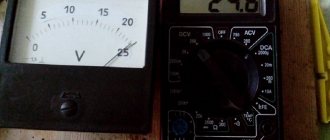
1. To check the presence or absence of voltage in electrical installations up to 1000 V, two types of indicators are used:
– bipolar – operating when active current flows;
– single-pole – operating at capacitive current.
2. Double-pole indicators are intended for electrical installations of alternating current and direct current, and single-pole indicators are intended for electrical installations of alternating current.
3. Double-pole indicators consist of two housings containing elements of the electrical circuit. The elements of the electrical circuit are connected to each other by a flexible wire that does not lose elasticity at low temperatures, with a length of at least 1 m. At the points of entry into the housings, the connecting wire has shock-absorbing bushings or thickened insulation.
4. The electrical circuit of a two-pole indicator with visual indication may contain a pointer-type device or a digital sign-synthesizing system (with a small-sized power supply for the indicating scale). Indicators of this type can be used for voltages from 0 to 1000 V.
5. The electrical circuit of a single-pole voltage indicator must contain an indication element with an additional resistor, a contact - tip and a contact on the end (side) part of the housing, with which the operator’s hand comes into contact.
6. The length of the non-insulated part of the contacts - tips should not exceed 5 mm. The tip contacts must be rigidly fixed and must not move along the axis.
7. Operational tests of voltage indicators up to 1000 V consist of determining the indication voltage, checking the circuit with increased voltage, measuring the current flowing through the indicator at the highest operating voltage, and testing insulation with increased voltage.
8. To check the indication voltage for a two-pole indicator, the voltage from the test installation is applied to the contacts - tips; for a single-pole indicator - to the contact - tip and the contact on the end (side) part of the housing.
9. The indication voltage of voltage indicators up to 1000 V should be no higher than 50 V.
10. To check the circuit for a two-pole indicator, the voltage from the test installation is applied to the contacts - tips, for a single-pole indicator - to the contact - tip and the contact on the end (side) part in accordance with the diagrams in Fig. 1.
11. The test voltage when checking the circuit must exceed the highest operating voltage by at least 10%. Test duration is 1 minute.
12. The value of the current flowing through the indicator at the highest operating voltage should not exceed:
– 0.6 mA for a single-pole voltage indicator;
– 10 mA for a two-pole voltage indicator with elements providing visual or visual-acoustic indication of the signal;
– for voltage indicators with an incandescent lamp up to 10 W with a voltage of 220 V, the current value is determined by the power of the lamp.
13. The current value is measured using an ammeter connected in series with the pointer in accordance with the diagram in Fig. 2.
14. To test the insulation of voltage indicators with increased voltage for bipolar indicators, both insulating bodies are wrapped in foil, and the connecting wire is lowered into a grounded vessel so that the water covers the wire, not reaching the handle by 9 - 10 mm. One wire from the test installation is connected to the contacts - tips, the second, grounded - to the foil and lowered into water in accordance with Fig. 3.
15. For single-pole voltage indicators, the insulating body is wrapped in foil along its entire length up to the limiting stop. A gap of at least 10 mm is left between the foil and the contact at the end of the housing. One wire from the test installation is connected to the contact - the tip, the second, grounded - to the foil.
16. The insulation of voltage indicators up to 500 V must withstand a voltage of 1 kV, and voltage indicators above 500 V - 2 kV. Test duration is 1 minute.
17. In operation, mechanical tests of indicators are not carried out.
Fig.1. Schemes for testing a single-pole voltage indicator up to 1 kV
Fig.2. Test circuits for a two-pole voltage indicator up to 1 kV
Fig.3. Schemes for testing the insulation of a two-pole voltage indicator up to 1 kV
Category Documentation, Instructions Tags: Tests, PPE, Voltage indicator