Every electrician knows how to use a multimeter, but an ordinary person may also need to use this device. If you need to clarify the serviceability of house wiring, radio components, find out how much electric current a particular household appliance consumes, what is the current strength in the network or its voltage, information about simple measuring manipulations with a multimeter will come in handy.
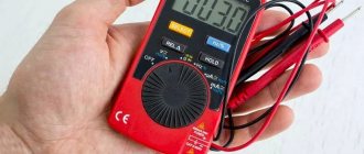
Multimeter ready to use Source bzns.media
Voltage and multimeter
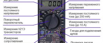
Let's see how to measure voltage with a multimeter. First of all, you need to check the location of the device toggle switch. To prepare the device for measuring voltage, you need to turn it from the off position (indicated as “OFF”) to the V~ mark (the English letter “V” and a wavy line indicating alternating voltage). On some multimeters this mode is abbreviated “ACV”. AC Voltage Test Steps:
- Install the red probe into the socket marked “V/Ω” or “VΩmA” (this is the positive potential), the black one into the “COM” socket.
On a note ! Since alternating voltage has no polarity, installing the probes into the precisely indicated connectors does not play any role. But if the black probe hits a phase, then the number on the screen may be negative.
- Check the switch (it should be at the V~ mark).
- Setting the test level (if you plan to measure alternating voltage in an electrical network with a nominal value of 220 Volts, you should set the test level to a slightly higher value, for example, 236 V, or perhaps to the maximum).
- Inserting the probes into the socket, for the voltage in which it is necessary to check.
Numbers indicating the desired alternating voltage will appear on the screen of the electronic multimeter.
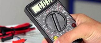
Dial multimeter in the off state Source img1.bgxcdn.com
Next, we'll look at how to use a voltage tester to check battery voltage. To measure DC voltage with a dial or electronic multimeter, insert a red and dark probe into the “V Ω mA” and “COM” sockets, respectively, then turn the switch to “V-”.
After setting the verification level (you will need to set it, as in the previous example, to a slightly larger digital value than the intended measurement object has). The two free ends of the probes must be connected to the object being tested (for example, to the two ends of a battery), observing the polarity (“+” and “-”).
On a note ! If you make the wrong polarity, the multimeter will show a negative value, but the value itself will be the correct number; you need to swap the probes on the battery so that the polarity is correct.
If a value with one or two zeros in front, but without a comma, appears on the device screen, it means that the test level was set too high. It is necessary to achieve a normal number by gradually reducing it and taking measurements. For example, for a battery the value “008” may first appear, and after the indicated manipulations - “8.9”. This means that the battery voltage is approximately 9 Volts.
The multimeter shows the battery voltage Source masteram.com.ua
When “1” appears on the screen, the pre-selected measurement threshold may be too high, then it needs to be brought to a suitable value by gradually decreasing it.
Checking the current strength
Let's see how to use the tester to find out the current strength:
- Insert the red connector into the socket marked “mA” (“VΩmA”), the black one into “COM” (to check the current strength, the value of which does not exceed 10 Amps). To check the current, which ranges from 200 milliamps to 10 amperes, you should put a red electrical probe into the “10A” connector.
Different positions of drills to determine small and large currents Source www.sciencebuddies.org
- Place the switch on the “A~” mark to check the alternating current value or on the “A-” mark to check the direct current strength.
- Set the measurement range so that it is greater than the expected current strength, but not by much.
- Connect the load (for example, an incandescent light bulb with a socket) into the assembled electrical circuit from the outlet to the multimeter.
Important ! You cannot touch the circuit elements that are not insulated with your hands and the ends of the probe.
- Attach a piece of wire to the lamp base, and the other end to the probe.
- Take another wire and attach it according to the “lamp base - electrical outlet” diagram.
- The red probe (its free end) must be set to the “+” of the object being measured, and the black probe must touch the next element of the circuit (the wire coming from the “load”, that is, from the light bulb).
Remember ! For correct, and most importantly, safe measurement of current, it is necessary to connect the multimeter to the electrical circuit in series, since in ammeter mode the resistance of the multimeter circuit is minimal and if connected in parallel there will be a short circuit.
Connection diagram for a multimeter with a “load” Source electrikmaster.ru
See also: Catalog of companies that specialize in electrical and heating systems
A multimeter can also be used to determine the amount of AC current consumed (for example, for a household appliance). After installing the switch on the direct current symbol (“A-”), you should arrange the probes as follows: for high current - the extreme left position (o), for low current - the middle position (o).
Having set the measurement range approximately corresponding to the current, but slightly larger, you can proceed to the next stage, not forgetting that the device can only be turned on in an open circuit (as in the previous example).
Using the battery
Testing the device with a battery is convenient and consists in the fact that the result of changing the polarity of the probes is that the multimeter produces absolutely identical voltage measurements.
When using a battery, the test mechanism is very simple and consists of several simple steps:
- selecting the operating mode of the electrical measuring device, which corresponds to measurements of the DC voltage level;
- setting measuring limits equal to 20 V.
After instrument probes are applied to the battery contacts, voltage readings are measured and data is taken.
A working battery shows a voltage of 1.35 V. However, low-demand devices may well use cells with a charge level of at least 1.2 V. Batteries with a minimum charge are subject to mandatory recycling.
Repeated testing allows you to check the capacitance indicators of the element under load conditions:
- connecting the multimeter probe to the contacts of the power element;
- parallel connection of the load element;
- maintaining a pause within 30-40 seconds;
- recording the obtained results.
Batteries with residual values of 1.1 V can be used exclusively in household appliances characterized by low energy consumption, but at the same time, the quality parameters of the equipment’s operation are significantly reduced.
It should be noted that ensuring maximum accuracy of the measurements obtained requires pre-setting the minimum limit of the measured voltage on the device, due to which the measurement error is easily determined.
It is important to remember that a voltage indication of 1.6 V when using standard “AA” batteries, as a rule, does not indicate a low level of accuracy of the electrical measuring device. Many manufacturers of new power supplies slightly increase the voltage level, which allows the battery to have the longest possible service life.
The most accurate data can be obtained by measuring with a load, and a traditional light bulb intended for installation in a flashlight is most often used as the main load element.
Multimeter and resistance
To find out the resistance of any radio component, use a conventional multimeter. Measurement algorithm:
- Insert the probes (black – into the “COM” socket, red – into the socket marked “V/Ω” or “VΩmA”).
- The switch will need to be moved to the “Ω” position.
- At the third stage, it is advisable to check the serviceability of the device by connecting the two remaining free ends of the probes. The multimeter is working if it shows a zero value.
- Set the measurement limit to the expected approximate average value (for example, 2 M).
- Connect electrical probes to the coil (to the measurement object).
What will be the coil resistance? Source cdn.sparkfun.com
- Look at the display (screen) of the device.
If several zeros appear, the coil has resistance, but the measurement limit will need to be lowered slightly to see the actual digital resistance value. The same must be done when a number appears in front of the numerical value on the electronic multimeter, but with a zero (zeros) at the beginning. If a unit occurs, it is worthwhile, on the contrary, to reduce the set denomination.
Instrument readings
Multimeters are represented by analog models and digital devices. All testers differ in functionality, as well as in the accuracy of the readings obtained. Popular analog multimeters show all data on the measurements performed with an arrow and a scale. Working with this type of device is not always convenient and requires some skill, and among other things, the pointer tester must be kept in a stably fixed position, which will not allow the pointer to “jump”.
Multimeter Aneng AN8001
In digital multimeters, measurement results, or rather readings, are displayed on a convenient LCD screen and have the form of intuitive digital values, which eliminates errors that inexperienced technicians make when taking data.
Testing with a multimeter
The multimeter has several more functions, one of which is the so-called continuity test. It is used to search for a break in the neutral wire in an electrical circuit.
Algori:
- connect the red probe to “V/Ω”, the black one to “COM”;
Testing wires with a multimeter to check their integrity Source avatars.mds.yandex.net
Checking radio components
If a radio amateur has a digital multimeter, he must know how to use this device to test the functionality and measure the characteristics of transistors, diodes and capacitors. Everything is very simple here:
A black probe should be installed in the COM socket, and a red one in the VΩmA socket.
The black probe (its second end) must be connected to the cathode of the diode (to the “minus”) of the part being tested, and the red one, respectively, to the cathode of the anode (to the “plus”).
The resistance of the part will be displayed on the screen.
If in any position (as in the described algorithm or with the reverse arrangement of the probes connected to the anode and diode) one is displayed, this means that the part has burned out. If the reading is less than one, the diode is broken.
Closing contacts in resistance measurement mode
In the absence of special equipment used to calibrate the measuring device, checking the accuracy of the readings obtained is determined not only with the help of a conventional battery, but also by closing the contacts in the resistance measurement mode.
It is necessary to pay attention to the fact that these works can be carried out exclusively in the resistance level measurement mode, since some models designed to measure other parameters often fail as a result of contact closure.
Resistance/continuity/diode test mode
After the probes are connected to the appropriate connectors and a contact closure occurs, the indicator of the measuring device should show a resistance of “O”. The presence of any other readings indicates a malfunction of the tester.
If necessary, resistor resistance is measured with known values. However, even serviceable multimeters, as a result of improper operation, can distort the data obtained. The standard connection rule is used, in which the red probe is connected to the positive pole, and the black wire to the negative.
The contact part on the probes must be kept clean, since the presence of solder or rust increases the resistance and distorts the measurement results.
Video description
You can see more details about how this test is carried out in the video:
To check the transistor, you need to switch the multimeter to the “hfe” mode and combine the three outputs of the part with the connectors on the device. They are called "B", "E" and "C" and correspond to the "base", "emitter" and "collector" on the transistor. If the connection is correct, the gain value of the radio component being tested will appear on the multimeter screen.
So, how to use a multimeter tester to check the capacitor for its capacity: this part must be inserted into the corresponding connectors on the device (the “CX” sector). By twisting the toggle switch, you can adjust the measuring limits to the required numerical value.
Video description
Learn how to quickly check a car battery with a multimeter in this video:
Checking a car battery using a multimeter Source mobilehomepartsstore.com
Further measurements will be made in the same way. To measure the current strength in the wiring of your car or for a separate electrical appliance, you should first find out what kind of current you need to check (for example, the “DCA” marking indicates constant). To measure resistance, set the toggle switch to any position, and do not forget to turn off the power to the network.
Properly checking the multimeter before purchasing
ATTENTION!!!
Under no circumstances should you purchase such a device secondhand on the market. Because there is a high risk of getting faulty equipment. Moreover, it is simply impossible to check it.
The best option is, in principle, a store with official registration, where:
- issue a receipt and guarantee;
- It is possible to check the functionality of the device.
Moreover, the consultant will give recommendations on how to use the multimeter and tell you how to properly calibrate it.
In any case, before transferring money, you need to at least inspect the case. Firstly, it should not show signs of use, cracks, chips or other defects. Secondly, you need to check the supplied wires.