How to properly connect circuit breakers in an electrical panel is a common question, because such actions require at least basic skills from the master. First, in accordance with the rules, you should draw up an electrical wiring project, decide on the installation location, draw up drawings, select a base and component elements. Only after the above steps do the craftsmen begin installation work, and then connect the shield to the cable.
Connecting machines in an electrical panel
Where is the electrical panel for the meter and automation installed?
The first step is to decide on a place to install the shield. So, experts believe that it is better to fix it near the entrance door in the corridor, because then you will not have to lay the cable from the landing, which will greatly simplify installation.
As a rule, the shield is fixed at the level of visibility of the residents of the apartment - this will allow you to easily take readings and turn off the machines. Therefore, the installation location will differ depending on the height of the household.
Note! There are still electricians who prefer to install meters under the ceiling (as they did before). Old designs were fixed to the wall without drawers, so they were fixed at a height for safety reasons.
Electrical panel in the apartment
Any modern shields have a secure base and are closed with a lock , so strangers or small children will not be able to get there if they do not have access to the keys.
When choosing a location for installation, they also take into account where the cable of the overhead or underground power line will pass from (in an apartment or private house). You can check this information with the employees of the company responsible for electricity.
Buy a ready-made electrical panel or assemble it yourself
Now electricians not only assemble the panels themselves, but also install a ready-made factory version with all the internal contents. Such designs are even made to special order for a specific apartment.
The main point in this matter is the experience of installing branded shields. If the master has already encountered such installation, then there is no need to be afraid. In other cases, it is better to assemble the structure on site, in stages.
Prices for electrical panels
Electrical panel
Video - Assembling a panel for an apartment
Connection diagram of machines in the electrical panel
Before you begin installing the machines, you need to carefully study their schematic design, because the installation diagram consists of several elements with different symbols.
Wiring diagram
Table 1. Elements used when installing an electrical panel.
| Name | Characteristic |
| Introductory machine | It is installed to protect the entire electrical wiring circuit. So, the cores of the main cable are fixed to the terminals of the machine. For ease of use, a switch is attached in front of the machine. It allows you to disconnect the current from the entire structure in order to carry out repair work. In this case, the power cable must also be connected to this switch. |
| Counter | It is placed after the machine guns. The main purpose of the meter is to control the consumed electricity . Sometimes it is fixed in another place even before the electrical panel along with the machines (on the landing). |
| Residual current device | The main function of the RCD is protection against electric shocks and fires . For example, in a small apartment, only one RCD is installed after the meter, because it is no longer required due to the minimum load. Sometimes several such devices are installed on lines where there is a large consumption of electricity. |
| Linear automata | They are required for lines to individual rooms. In the presence of high voltage or short circuit, they break the circuit, thereby preventing fire or short circuit . They are needed to protect various electrical appliances. |
| Differential machines | They are installed instead of several main circuit breakers with a protective device on separate lines for various household appliances. |
| Mounting rail | The rail is fixed to the rear wall of the base of the shield. Depending on the size of the box, the number of slats and modules may vary. In order to purchase a shield for a certain number of modules, a detailed drawing of the connections is first drawn up. |
| Comb | They are intended for the purpose of disconnecting the shield in order to connect the neutrals to the grounding connections. One shield has zero combs and grounding combs. |
| Distribution bus | They connect linear, differential circuit breakers and protective devices. They are reliably insulated, thanks to which they securely fix the machines through the input clamp. They are used for both phase and zero. |
Electricity meter
First, I’ll answer the question - 16A how many kilowatts (kW)?
Everything is very simple - the voltage in the home electrical network is 220V (Volts), to find out how much a 16A outlet can withstand - 220 X 16 = 3520 Watt, and as we know in 1 kW - 1000 W, it turns out - 3.52 kW
If the formula from school physics is P= I * U, where P (power), I (current), U (voltage)
In simple words, a 16A socket in a 220V circuit can withstand a maximum of 3.5 kW!
Induction hob and socket
An induction hob consumes 7.5 kW of energy with all 4 burners turned on. If you divide in reverse order, you get 7.5kW (7500W)/220V = 34.09A
As you can see, the 34A consumption will simply melt your 16A socket!
Well, okay, you think...
Then I’ll install a 32-40 A outlet and connect the stove! But that was not the case, you need to know what wire you have in the wall, and also what machine everything is connected to in the panel!
The thing is that the wires also have a maximum power threshold! So if you have a wire with a cross-section of 2.5 mm, then it can withstand only 5.9 kW!
Also, the machine should be set to 32A, or better yet, 40A. Once again I recommend this article! More details there!
So calculate correctly! Otherwise, your socket-wiring will melt from the high voltage and a fire could easily occur!
Heresy, the formula presented in the article is suitable for constant voltage, but in everyday life variable voltage is used, that is, there is a coefficient Fi.
Dmitry, this is exactly the case for ordinary household sockets!
Fortunately, the above formula is only suitable for constant voltage. For AC (as in a socket), this will allow you to approximately estimate the power of the device. In principle, it will be sufficient for domestic use. The socket will melt not from high voltage, but from high (for it) current. It is the current that heats up the conductor. And insulation depends on voltage. Roughly speaking, the higher the voltage, the thicker the insulation.
Still, it is more important to take the current into account. The core cross-section is larger, the current is higher. Copper or aluminum. The outer insulation can withstand current and voltage. It would be wrong to take only voltage into account.
Please tell me, is it possible to lay a multi-core wire in the wall and what cross-section for a current of 16 Amps? I don’t want to take a single-core cable.
Alex, what kind of cable? How many amperes is it rated for?
Alex, you can put it in, BUT it must be in a corrugated box, that’s the point? 16 Amp wire, that’s nothing at all! You need to calculate at least 30 - 40 Amps, take copper with a cross-section of 2.5 mm!
The socket does not burn out due to increased voltage - the voltage is the same = 220V) And it was Admin who mistyped it. Secondly, the cross-section of the wire can be selected based on the fact that Aluminum 1 square has a carrying capacity of 7 amperes, Copper 1 square - 10 amperes. Output = 2.5 square copper cable rated at 25 amperes. All this “calculation” is at the everyday level, but it is quite suitable. If you need to power an 8 kW device, then this is an average of 40A, which means you need a copper wire with a cross-section of 4 squares. NOW ABOUT SECONDARY THINGS)) - We wrote above about the cosine phi, let me explain - if the current-voltage characteristic “VA” is written on the device, then Yes, you need to take into account the coefficient phi. For example, an 8000 VA current stabilizer is NOT for an 8 kW consumer. for everyday life and household appliances, an average coefficient of 0.8 is accepted, which means we multiply 8000 VA by 0.8 and get the average maximum permissible load on the stabilizer. For ten-type heating devices (for example, in old electric stoves or kettles, but NOT for an induction cooker), the phi coefficient is equal to one. That is, in this case, a stabilizer with 8000 VA will pull an old electric stove with a power of 8 kW, but will not pull a bunch of different electrical appliances (or an induction stove) with a total power of 8 kW, since for a bunch of appliances the coefficient is no longer 1 but 0.8
What are circuit breakers
Automatic switches are specialized devices whose main task is to protect electrical wiring from fire. Of course, they are not able to protect against electric shock or damage to household appliances, but they do control overheating.
Operation is based on the fact that the devices break the electrical circuit in the following situations:
- short circuit;
- a sharp increase in voltage in the conductor (above a certain norm).
Usually the machine is fixed at the entrance, which allows you to protect the section of the chain that follows it. Since all elements are wired differently, protection devices must operate at different current levels.
Some novice electricians may think that fixing a power-hungry circuit breaker is enough, but this is a common misconception. After all, if the protective device does not work in the presence of high current, then the wiring will catch fire.
Automatic switch made in Russia
Machine device
Most often, the machine is a structure of the following elements:
- Cocking handle . It allows you to turn on the device or turn it off if installation is necessary.
- Actuating mechanism.
- Contacts . They connect and break the common chain.
- Clamps . Used to connect to a protective device.
- Mechanisms that operate according to conditions. This includes the bimetallic thermal release plate. Some designs have an adjustment screw with which you can adjust the current strength.
- Arcing chambers a. Located in any pole of the device.
Depending on the purpose, the machines are equipped with additional elements
How does the shutdown mechanism work?
The machine has a special mechanism that helps break the chain when the current increases.
There are different operating principles for such devices:
- Electromagnetic . A distinctive feature is rapid operation in the presence of a short circuit. With a sharp increase in current strength, a coil is activated, the core of which opens the circuit.
- Thermal . Here the main element is a bimetallic plate, which, when the temperature rises, changes shape, bends in the opposite direction, due to which it opens the chain.
Electromagnetic devices
Electric kettles operate on a similar principle, which is why they turn off when the water boils. Semiconductor devices are also used to break the circuit, but they are rarely used in networks.
Markings on machines
All machine models have different designations by which they can be identified. Typically, most manufacturers prefer to produce designs that can be used in various conditions and industries.
In order to eliminate errors during connection, you should understand the markings on the body part:
- Logo . Most often, you can find the manufacturer’s logo at the top of the machine. In addition, all brands produce products in a certain color range. This means that it will not be difficult for the average user to find the right option.
- Indicator window . Determines the current state of contacts. If the switch breaks down, in this window you can see the voltage in the network or its absence.
- Device type . In standard networks, machines of types C and B are usually used. They differ from each other in their sensitivity coefficient.
- Rated current . The maximum current value is shown here. Often two values are indicated - for single-phase and three-phase networks.
- Maximum permissible switching current . Indicates the voltage limit during a short circuit, due to which the machine turns off, but remains operational.
- Scheme . Sometimes on the machine you can even find a contact connection drawing, which is located on the side.
Marking location
Which machine to choose
When choosing a device, you should first take into account its maximum permissible current . To do this, you need to calculate what current strength is required for all devices installed in the apartment.
In addition, the thickness of the wiring also matters, since electricity flows through it. The optimum value is required depending on the degree of heating. The presence of poles is also of great importance:
- One . Chains with lighting fixtures and sockets to which only primitive devices are connected.
- Two . It is used to protect electrical wiring that is supplied to large appliances (washing machines, stoves, refrigerators, heating, water heaters). In addition, it is installed for additional protection between the electrical panel and the apartment.
- Three . Relevant in the presence of a network with three phases, which happens at manufacturing enterprises and their own workshops.
Single-pole circuit breaker
The machines are installed in the panel according to the standard principle - from largest to smallest. This means that first they fix the machine with two poles, and only then with one. This is followed by other devices with lower power.
Prices for automatic machines
Difavtomat
Video - RCD or differential circuit breaker: what to choose
Manufacturers
Circuit breakers are manufactured in many countries. The main requirement for this device is that it must be made of high-quality materials and have a long service life. The price of an automatic machine of the same power can vary quite widely and depends on the manufacturer.
The highest quality machines are produced by the following companies:
- French: Legrand, Schneider Electric, Hager;
- Slovak SEZ Krompachy;
- German: ABB, Moeller, Kopp;
- American General Electric;
- Russian: Kontaktor, KEAZ.
Features of connecting circuit breakers
After you decide on the type of machines, you need to connect them. If you follow certain steps, you can cope with this process without any special skills.
General recommendations for assembling an electrical panel
Here we will look at the process of step-by-step assembly of an electrical panel for a one-room apartment. First you need to prepare all the tools and components that will be used during the installation process:
- switch box;
- metal scissors;
- insulation stripping tool (stripper);
- side cutters;
- cable cutter;
- screwdriver;
- screwdriver;
- wires;
- combs;
- full set of automation.
Prices for voltmeters
Voltmeter
You should prepare your tools in advance
Assembling the shield - step-by-step instructions
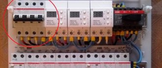
Step 1. First of all, we need to place the automation on the top rail, in such a way as it should look after fixing. First we install the switch, then the UZM (protective device), after which three RCDs for different groups (leakage current 30 mA , rated 63.63 and 40 A ).
The first is for 40 A - light, the second is for 63 A - for the hob and oven, the third is for 63 A - for the remaining groups. At the end, one differential machine of type “A” is installed, because such devices are recommended by manufacturers of most household appliances.
When starting work, lay out all the necessary tools in front of you.
Step 2. Next, you need to go to the second rack and place the machines in the correct position. They must be placed strictly under a specific group of RCDs. You should start on the right side.
Thus, under each group all nine modules will be located
Step 3. Now the automation needs to be powered together. For such purposes, combs should be used in two configurations. The first is PS-1 for 12 modules. The second is PS-2 for 12 modules. Since we only have 9 modules, the excess section of the comb will need to be removed with a machine with a special disk. So, first you need to power the upper module.
Mark the required distance on the comb and cut with a disk
Step 4. When the miniature comb is ready, you will need to insert it into the automation, and then tighten the screw fastenings.
The screws of the first RCD should not be touched, because power will be supplied there by wires
Step 5. Now you need to power the lower automation using a similar principle. Here you will have to take into account some nuances. There is no need to saw off the copper together with the plastic part; they should be cut off separately. This will eliminate the need for side plugs. Thus, the plastic part will be longer than the copper one, thereby providing additional safety.
Since the automation is divided into three parts, the copper part will also need to be divided (two modules, two modules, 5 modules). After which these three parts can be used under a single plastic comb.
Installing the lower comb
Step 6. Next, you need to suppress the power from the switch on the UZM, this will allow you to check the functionality. To do this, we need to prepare two cables of 10 square millimeters - black and blue (for phase and neutral). You will need to first cut the cables to the required length, then remove the insulation at the edges, and only then connect them.
Thus, the connection between the switch and the UZM should look like this, which needs to be checked
Step 7. Check the connection is working. To do this, we need to prepare a power cable with a plug at one end and connections at the other. One side should be connected to the machine, and the plug should be plugged into the socket (in the second step).
Now you need to set the approximate value of the UZM, which will allow you to check the functionality, after which the load is disconnected, as is the power cable
Step 8. Next, you need to supply power to the first RCD, because we have already powered all the others with a comb. Here, too, it is necessary to cut the cable of the required size, why strip its ends and connect power from the RCD to the first RCD.
Next you will need to check using the same power cable
Step 9. The next step is to move all the lower machines to the right side and fix them with a limiter.
Tighten the limiter screw
Step 10. Now you need to remove the power cable and transfer the structure to the panel. Now you need to move on to the stage of installing zero buses. There are three RCDs and the same number of buses.
You will need to install busbars and connect each RCD to the busbar. This should be done using a 6 square millimeter cable. In this case, you will also need to cut the required size and remove the insulation.
We connect each RCD one by one to its zero bus
Step 11. Next, we need to power groups of machines to each RCD. Now you will need to take a cable of the same cross-section, but only red. Here, too, you should measure the required length, clean it, and only then connect it.
This is what the final connection will look like
At this stage, the process of connecting all elements of the panel is considered complete. Now you just need to tighten the screw fastenings, check the functionality of the device again, and close it with the lid. In addition, it is advisable to label the automation in order to understand the sequence of components.
Note! The load wires and power cable should be secured at the installation site.
Video - Installation of an electrical panel
First, I’ll answer the question - 16A how many kilowatts (kW)?
Everything is very simple - the voltage in the home electrical network is 220V (Volts), to find out how much a 16A socket can withstand is enough - 220 X 16 = 3520 Watt, and as we know in 1 kW - 1000 W, then it turns out - 3.52 kW
If the formula is from school physics P= I * U, where P (power), I (current), U (voltage)
In simple words, a 16A socket in a 220V circuit can withstand a maximum of 3.5 kW!
Induction hob and socket
An induction hob consumes 7.5 kW of energy with all 4 burners turned on. If you divide in reverse order, you get 7.5kW (7500W)/220V = 34.09A
As you can see, the 34A consumption will simply melt your 16A socket!
Well, okay, you think...
Then I’ll install a 32-40 A outlet and connect the stove! But that was not the case, you need to know what wire you have in the wall, and also what machine everything is connected to in the panel!
The thing is that the wires also have a maximum power threshold! So if you have a wire with a cross-section of 2.5 mm, then it can withstand only 5.9 kW!
Also, the machine should be set to 32A, or better yet, 40A. Once again I recommend this article! More details there!
So calculate correctly! Otherwise, your socket-wiring will melt from the high voltage and a fire could easily occur!
Heresy, the formula presented in the article is suitable for constant voltage, but in everyday life variable voltage is used, that is, there is a coefficient Fi.
Dmitry, this is exactly the case for ordinary household sockets!
Fortunately, the above formula is only suitable for constant voltage. For AC (as in a socket), this will allow you to approximately estimate the power of the device. In principle, it will be sufficient for domestic use. The socket will melt not from high voltage, but from high (for it) current. It is the current that heats up the conductor. And insulation depends on voltage. Roughly speaking, the higher the voltage, the thicker the insulation.
Still, it is more important to take the current into account. The core cross-section is larger, the current is higher. Copper or aluminum. The outer insulation can withstand current and voltage. It would be wrong to take only voltage into account.
Please tell me, is it possible to lay a multi-core wire in the wall and what cross-section for a current of 16 Amps? I don’t want to take a single-core cable.
Alex, what kind of cable? How many amperes is it rated for?
Alex, you can put it in, BUT it must be in a corrugated box, that’s the point? 16 Amp wire, that’s nothing at all! You need to calculate at least 30 - 40 Amps, take copper with a cross-section of 2.5 mm!
The socket does not burn out due to increased voltage - the voltage is the same = 220V) And it was Admin who mistyped it. Secondly, the cross-section of the wire can be selected based on the fact that Aluminum 1 square has a carrying capacity of 7 amperes, Copper 1 square - 10 amperes. Output = 2.5 square copper cable rated at 25 amperes. All this “calculation” is at the everyday level, but it is quite suitable. If you need to power an 8 kW device, then this is an average of 40A, which means you need a copper wire with a cross-section of 4 squares. NOW ABOUT SECONDARY THINGS)) - We wrote above about the cosine phi, let me explain - if the current-voltage characteristic “VA” is written on the device, then Yes, you need to take into account the coefficient phi. For example, an 8000 VA current stabilizer is NOT for an 8 kW consumer. for everyday life and household appliances, an average coefficient of 0.8 is accepted, which means we multiply 8000 VA by 0.8 and get the average maximum permissible load on the stabilizer. For ten-type heating devices (for example, in old electric stoves or kettles, but NOT for an induction cooker), the phi coefficient is equal to one. That is, in this case, a stabilizer with 8000 VA will pull an old electric stove with a power of 8 kW, but will not pull a bunch of different electrical appliances (or an induction stove) with a total power of 8 kW, since for a bunch of appliances the coefficient is no longer 1 but 0.8