The operating principle of the 380V electromagnetic starter connection diagram
In modern power engineering, electromagnetic starters are widely used.
These are devices designed to repeatedly turn electrical devices on and off.
The task of the device in question is to close and open contacts of electrical circuits of different power, at voltages up to 440 V DC and 600 V AC.
In their design they have:
- a certain set of working contacts designed to supply voltage to the power plant;
- auxiliary contacts - intended for control and signal circuits.
Main differences between starters and contactors
In terms of their design, contactors are similar to starters. They perform the same task, serve the same type of goals. In order not to get confused in this matter, we suggest considering the differences between these devices.
The main distinguishing feature of the contactors is the presence of a powerful arc-extinguishing chamber. As a result, they are used in circuits where high currents are present, and have a much greater weight in relation to the electromagnetic starter.
Accordingly, starters, without arc chutes, are designed primarily for operation where low-power currents flow. Their operating range is up to 10 amperes.
Another design feature of electromagnetic starters is the presence of a plastic case, where the contact pads are brought out. In contrast, most contactors are manufactured without a housing. To isolate from dust, rain, as well as accidental contact with live parts, they are installed in protective boxes or boxes.
Another difference is the purpose of the 380 V electromagnetic starter. Its task is to switch the circuits of three-phase motors. Three pairs of power and one pair of auxiliary contacts are an integral part of this device. The first ones are intended for connecting 3 phases, and the second one serves to supply power to the engine after releasing the “start” button. This operating algorithm is quite common and is suitable for a large number of devices. In this connection, various technical units and devices are connected through these electromagnetic devices.
Let's highlight the main differences :
- compactness;
- design features;
- appointment.
Due to the similarity of functionality and filling, some companies sometimes call electromagnetic starters “small contactors” in their price lists.
The main circuit has two parts: Three pairs of power contacts that direct electrical power to electrical equipment. Disabling the magnetic starter in this case is possible only if the control coil circuit is broken, which makes it obvious that it is necessary to use a button with a break contact.
And it cannot be adjusted exactly to the rated current of the motor. For example, you can supply power to the coil through a time relay or a light sensor, and connect the street lighting power line to the contacts.
Design and principle of operation To better understand the connection diagrams of a magnetic starter, you need to understand its structure and principle of operation.
Each of them has a pair of inputs and a pair of outputs. Tweet on Twitter Magnetic Starter Wiring Diagram A magnetic starter is a low voltage electromagnetic combined device for distribution and control, designed to start and accelerate various electric motors.
We recommend: How to repair wiring in an apartment
It is also impossible to install the MP in the same room with devices that have a current higher than A. Now, if you release it, the magnetic starter continues to operate until the voltage disappears or the thermal relay P of the motor protection is triggered.
It is shown in detail in what order it is better to connect the wires in the following video. There are no changes in phase A. There is also usually a ground terminal. Now you can connect the wires or cables of the power circuit, not forgetting that next to one of them at the input there is a wire to the control circuit.
Contactors have powerful arc extinguishing chambers. The contacts close, power is supplied to the load, and as a result, it starts working. Diagram with coil connection per volt. Analyze the design with voltage per volt.
Therefore, in production, winding switching is used to start especially powerful electric motors. As a result, the motor M will change the direction of rotation. Buttons for controlling the electric motor are included in push-button stations; push-button stations can be one-button, two-button, three-button, etc. An electromagnet in the form of a coil with a large number of turns is designed for a voltage of 24 V. In this case, power is provided using two phases L2 and L3, whereas in the first case - L3 and zero. How to connect a magnetic starter PME - 071 - 380 volts - How to connect a magnetic starter
Design and principle of operation
The basis of the starter is an inductance coil and a magnetic circuit, consisting of moving and stationary parts. The fixed part is the lower one and is fixed to the body, the upper one is spring-loaded and can move freely.
A coil is mounted at the bottom of the magnetic circuit, and the rating of the contactor changes in direct proportion to its winding. Coils are available from 12 to 380 volts.
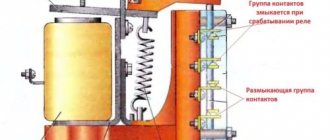
As for the upper part of the magnetic circuit, there are movable and fixed groups of contactors.
When there is no power, the springs press out the part of the magnetic circuit located at the top. In this case, the contacts are in the idle or initial state. When voltage is applied, an electromagnetic field is generated in the coil, under the influence of which the upper part of the core is attracted. As a result, the contacts change their position.
When the voltage is removed, the system returns to its original state . The contacts close when voltage is applied and open when it is removed. The electromagnetic starter operates on both direct and alternating currents, the main thing is that the parameters are no more than those specified by the manufacturer.
EMF design features
The design of an electromagnetic starter (EMF) is not highly complex. But this factor does not in any way reduce the reliability of the device.
How does this device work?
The reliability criterion is, for the most part, established by the correct connection of the circuits and the precise selection of the load.
If these criteria are met, the device will operate flawlessly for a long time in most cases.
The classic design of electromagnetic devices - starters, which are widely used in the field of power supply. There are many options for such devices, differing in shape and size.
The classic version includes the following elements:
- The body is dismountable in two halves.
- Inductor.
- Magnetic core.
- Switching mobile chassis.
- Group of main contacts.
- Group of auxiliary contacts.
The element of the magnetic starter, responsible for organizing the switching of the power circuit, is a movable chassis combined with one part (moving) of the magnetic circuit.
The chassis itself is made of dielectric material, and metal (brass) plates are used as closing contacts. At the ends of the plates there are contact patches made of refractory metals, usually a silver alloy.
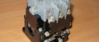
A disassembled electrical switching device with a full set of parts included in the design. This is a simple classic device, while more advanced modern devices have a somewhat more complicated design.
The fixed part of the magnetic circuit is rigidly mounted inside the second half of the electromagnetic starter housing. An inductance coil is placed on this part of the magnetic circuit and a return spring is installed.
The second part of the device body is also equipped with contacts for power and auxiliary groups. These contacts are rigidly fixed to the housing using screws.
This is what the contact power group of one of the starter designs looks like in a classic design. Meanwhile, the design of the devices is characterized by a variety of configurations, which does not allow specific reference to individual parts.
The design of a standard magnetic starter involves combining two halves of the housing, as a result of which the two halves of the W-shaped magnetic circuit are also combined into a single structure.
At the same time, due to the return spring, a small gap remains between the halves of the magnetic circuit; the main contact groups in this position remain broken.
Operating principle of EMF
The operating principle of the device is based on the effect of electromagnetic induction. If there is no voltage on the coil located inside the starter, the magnetic circuit remains in the “with gap” position, the main contacts are broken.
The inductor of a classical device, the force of the magnetic field of which attracts the contact moving chassis. And an ordinary metal spring, due to which the movable chassis is pressed out
When an electric current is passed through the coil, under the influence of a magnetic field, the second (moving) part of the magnetic circuit overcomes the force of the spring and is attracted to the first (fixed) part.
Accordingly, the main contact groups of the starter are closed by the plates of the movable chassis.
The reverse process is obvious - when the voltage is removed from the terminals of the inductor, the magnetic field ceases to operate, and under the force of the return spring, the movable chassis and the second part of the magnetic circuit are repelled. Accordingly, the magnetic starter returns to the contact-break state.
The second is the upper moving part of the assembly, thanks to which the switching principle is carried out. On the right, individual contacts of the power group are also shown, dismantled from the seats of the insulated housing
It should be noted that based on the configuration of the electrical device, the circuit of contact groups can have a very different structure. Especially regarding auxiliary contacts, which may be in a closed or open state in contrast to the state of the main contacts of the device.
A feature of modern designs of magnetic starters is the modernization of the inductor control circuit.
If the design of previous “outdated” devices involved direct supply of voltage to a coil taken from one of the phases, electronic circuits are now increasingly used.
The design of an electrical line switch, where an additional electronic board is used in the inductor power supply circuit. After processing by the board, the coil receives a DC supply voltage
For example, known products are equipped with an electronic circuit for stabilizing the voltage supplied to the terminal of the inductor coil of the magnetic starter.
Controlling the coil through an electronic circuit is characterized by the fact that the alternating voltage is first rectified and then a pulse signal is generated. This approach provides increased service life and improved stability of operation.
Electric motor connection diagram 380
We will talk about connecting an asynchronous electric motor when connecting the windings with a star or delta in a 380 V network.
For normal operation of the electric motor, a neutral conductor (N) is not needed, but a protective conductor (PE) is required: it serves to protect the consumer from electric shock when one of the phases breaks down on the housing.
The starter coil is powered through phases L1 and L2. L1 is connected directly, and L2 is connected through the “stop” button - 2, the “start” button - 6, the thermal relay button - 4, which are connected in series to each other.
When you press the “start” button - 6, through the thermal relay button 4, voltage L2 is supplied to coil 5. This is followed by the retraction of the core and the closure of contact group 7 to the load of the electric motor M, as a result of which an electric current corresponding to a voltage of 380 V is supplied.
When the “start” button is turned off, this circuit is not interrupted, and the current passes through the movable block - 3, which closes when the core is retracted. In the event of an accident, thermal relay 1 is activated, contact 4 is broken and the coil is turned off. Return springs return the core to its original position. Voltage is removed from the emergency area when the contact group opens.
Application of a magnetic starter
A magnetic starter (or contactor) is used to remotely switch on electrical equipment.
The advantage of a starter over simpler circuit closing devices (for example, a switch) is the separation of power and control circuits. This allows the starter to be placed in the power cabinet, and the controls to be placed in the work area. At the same time, control voltage and currents are minimal, which allows the use of wires of smaller cross-section. With increased safety requirements (high humidity in the room), it is enough to simply use a starter with a coil, for example, 24 V. The supply voltage of the electrical equipment can be 220 or 380 Volts.
In addition, the starter connection diagrams ensure safety in the event of a power failure in the network. In the event of a voltage failure, the power contacts open, and if voltage occurs, the starter will not supply voltage to the electrical equipment until it receives power through the start button.
An example from life. Some kind of lathe or milling machine is working. The tension is gone. The machine stopped. The worker started to adjust something in the working area of the machine, and then the tension appeared again. If the machine were controlled by a switch, the engine would immediately turn on, resulting in injury. When controlling the power supply using a magnetic starter, the machine will not turn on until the Start button is pressed.
Below is a diagram of a simple starter switch to control the supply of voltage to electrical equipment. In our example, this is an asynchronous electric motor with a phase-to-phase supply voltage of 380 V. Accordingly, the voltage in one phase relative to zero is 220 V. The starter coil is designed for a voltage of 220 V.
In the initial position, we have voltage on power contacts 1, 2 and 3 of the starter, as well as on contact 1 of the “Start” button (normally open).
When you press the “Start” button, voltage is supplied to contact K2 of the starter coil through the normally closed contacts of the “Stop” button, closing the coil power circuit.
The coil creates a magnetic field, the core is attracted, closing the power contacts of the magnetic starter (1 and 4, 2 and 5, 3 and 6, respectively). In this position, voltage is supplied to the electric motor. At the same time, the NO block contact closes, the phase from which is supplied to the starter coil through the “Stop” button. Therefore, even when we release the "Start" button, the coil circuit remains closed, ensuring the closed position of the power contacts.
When the “Stop” button is pressed, the coil circuit is broken and the spring returns the power contacts to the initial (open) position. Accordingly, the voltage disappears from the wires supplying the electric motor, as well as from the NO block contact.
Similarities and differences between contactors and starters
Both devices serve to close and open the circuit as needed. Their design is based on an electromagnet; they operate on both alternating and direct current. Equipped with power, or main, as well as signal, or auxiliary, contacts.
The difference lies in the degree of protection of the devices. Contactors are equipped with a chamber for extinguishing the arc. Due to this feature, they are used in circuits with higher power than starters. In addition, the device itself is more massive due to arc suppression chambers. The maximum permissible current for starters is up to 10 amperes.
The starters are made in a plastic case and are equipped with eight contacts - six for powering a three-phase motor, and two for providing it with power after the “start” button is stopped pressing. They are used both to power electric motors and devices for which this circuit is suitable.
Contactors are often manufactured without a housing, so during operation it is necessary to provide them with a protective casing that protects it from moisture and contamination, and electric shock to people.
How does a starter work?
The main parts of the device are an inductive coil and a magnetic circuit, consisting of static and dynamic W-shaped parts. They are located with leads facing one another. The stationary part is fixed to the body, and the movable part is not fixed. At the bottom of the magnetic circuit, an inductance coil is inserted into a special slot.
Depending on its parameters, the nominal operating voltage of the device changes - from 12 to 380 volts. At the top of the magnetic circuit there are two pairs of contacts - static and dynamic.
When there is no power, a spring keeps the contacts open. When power appears, a magnetic field is induced in the coil, and the upper core is attracted to the lower one. As a result, the contacts are closed. After removing the power, the electromagnetic field also disappears, and the spring opens the contacts.
The device can operate from a direct current source, and with single- and three-phase alternating current, the main thing is that its values do not exceed the rating specified by the manufacturer.
220 volt network
When powered from a 220 volt single-phase network, the connection is made through the terminals, which are usually designated A1 and A2. They are located at the top of the starter housing. When a wire with a plug is connected to them, the device is connected to the network. The terminals marked L1, L2, L3 are supplied with any voltage removed from contacts T1, T2 and T3.
When connecting to a device, zero and phase can be easily transferred, this is not important. Typically, power is supplied through a temperature or light level sensor, for example, when connecting the starter to autonomous heating or street lighting.
Start and stop buttons
When starting and stopping the engine using a starter, it is convenient to connect a device with buttons connected in series with the device.
To ensure that the engine does not stop working after pressing the “start” button, self-retaining is introduced into the circuit due to the terminals paralleled with the “start”. Thanks to them, the engine runs after the “start” button is no longer pressed, until the stop button is pressed.
Voltage is supplied to the motor through any contact marked with the letter L, and it is removed from the corresponding contact under the letter T. This connection diagram is valid for a single-phase network.
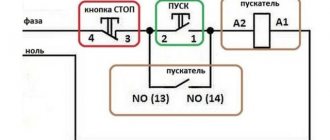
MAGNETIC STARTER CONNECTION DIAGRAM
Before we begin the practical connection of the starter, let us recall a useful theory: the magnetic starter contactor is turned on by a control pulse emanating from pressing the start button, which supplies voltage to the control coil. Keeping the contactor in the on state occurs according to the self-retaining principle - when an additional contact is connected in parallel with the start button, thereby supplying voltage to the coil, as a result of which there is no need to hold the start button pressed.
Disabling the magnetic starter in this case is possible only if the control coil circuit is broken, which makes it obvious that it is necessary to use a button with a break contact. Therefore, the starter control buttons, which are called push-button posts, have two pairs of contacts - normally open (open, normally closed, NO, NO) and normally closed (closed, normally closed, NC, NC)
This universalization of all the buttons of the push-button station was made in order to anticipate possible schemes for providing instant engine reverse. It is generally accepted to call the shutdown button the word: “ Stop ” and mark it in red. The turning button is often called the start button, start button, or is designated by the words “ Start ”, “ Forward ”, “ Back ”.
If the coil is designed to operate from 220 V, then the control circuit switches the neutral. If the operating voltage of the electromagnetic coil is 380 V, then a current flows in the control circuit, “removed” from the other supply terminal of the starter.
Connection Instructions
Connection to a 3-phase network It is possible to connect 3-phase power through an MP coil operating from V.
If the inscription reads V AC or there is an AC symbol next to it, then a phase and a zero are required for the control circuit to operate. The latter is designed for quick disconnection of contacts, the speed of which determines the magnitude of the electric arc. This is an important aspect, because if connected incorrectly, the core may burn out or will not fully start the necessary contactors. A graphical representation of the control, which consists of a coil, buttons and additional contactors that take part in the operation of the coil or prevent erroneous activation. Now, having double-checked the correct installation, you can apply voltage and check the functionality of the circuit. This attachment snaps into special holders; its contact groups work together with the groups of the main body. After completing the above steps, the electric motor will be turned off and ready for subsequent start-up from the push-button station. Starter control buttons In general, you will need two buttons: one to turn on and one to turn off. The need for a specific push-button contact It is known that the contactor of a magnetic starter is turned on by a control pulse emanating from pressing the start button, which applies voltage to the control coil. MP connection diagrams differ mainly depending on which coil is located in it. Such buttons usually have two pairs of contact groups - one normally open, the other closed.
Search on the site
Reversible circuit for connecting an electric motor through starters In some cases, it is necessary to ensure that the motor rotates in both directions. Keeping the contactor in the on state occurs according to the principle of self-retaining - when an additional auxiliary contact bypasses and is connected in parallel with the start button, thereby supplying voltage to the coil, as a result of which there is no need to hold the start button pressed. With a cross connection scheme, simultaneous operation of both starters will result in a short circuit. The coil will activate the KM1 contacts and they will close the circuit with the motor windings. Voltage with a designation means different phases.
When the armature is completely lowered, the contacts thrown by the spring are disconnected. The power supply to the control coil after connecting the magnetic starter is supplied by alternating current, but for this device the type of current does not matter. A correctly connected starter should be locked in the on position when mechanically pressing on the moving part of the magnetic circuit. The type of voltage does not matter, the main thing is that the rating does not go beyond V. Now, if you release it, the magnetic starter continues to operate until the voltage disappears or the thermal relay P for motor protection is triggered. At the same time, the starter core attracts the armature, resulting in the closure of the moving power contacts, after which voltage is supplied to the load.
But there is only one correct one. This is the so-called push-button post. You can also make a single-line graphic drawing of the connection of a three-phase electric motor to a magnetic starter via a relay. Magnetic switch. Or how to connect a three-phase motor
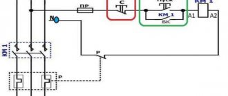
Connection diagram for a 220 V magnetic starter
Here, the current is supplied to the magnetic coil KM 1 through a thermal relay and terminals connected in a chain of buttons SB2 for turning on - “start” and SB1 for stopping - “stop”. When we press “start”, electric current flows to the coil. At the same time, the starter core attracts the armature, resulting in the closure of the moving power contacts, after which voltage is supplied to the load. When “start” is released, the circuit does not open, since the KM1 block contact with closed magnetic contacts is connected parallel to this button. Thanks to this, phase voltage L3 is supplied to the coil. When you press “stop,” the power is turned off, the moving contacts return to their original position, which leads to de-energization of the load. The same processes occur when the thermal relay P operates - a break in the zero N supplying the coil is ensured.
Magnetic starter design
The picture below shows the components of a typical starter. The stationary lower part, when the coil is connected to the power supply, forms an electromagnetic field that attracts the moving element. The contacts connected to the armature close the operating circuit. If the winding is de-energized, the spring will return the system to its original state.
Main functional elements of the starter
The core of the electromagnet is assembled from plates in the shape of the letter “W”. A large number of components block parasitic currents (skin effect). The number of turns is selected taking into account the supply voltage.
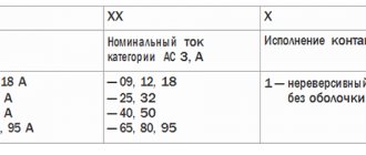
Sectors with designations
Explanatory inscriptions on the body are divided into three groups:
- general information and scope (AS1-4);
- information about permissible currents in load circuits (conversion to kW or reverse is performed taking into account the mains voltage);
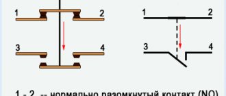
- graphic designation of contact groups (the broken line indicates synchronous switching).
Each area can be explored in detail. To familiarize yourself with the classification by purpose categories, follow the standards of GOST R 50030.4.1.-2002. The designation AC1 indicates the possibility of connecting the starter to heating elements, incandescent lamps and other loads with weakly expressed reactive characteristics. If you need to ensure the start of a powerful engine, choose a model of the AC3 category.
Contact attachment
This part is mounted on a 220V electromagnetic starter to expand the basic functions:
- activation of reverse engine mode;
- additional load management;
- turning on the light indication.
Contact attachment
Note. A typical attachment mechanism contains two pairs of contacts. Rigid fixation of the block in a certain place is ensured by the special shape of the protrusions of the docking platform. When choosing the appropriate model, you should take into account the compliance with the starter, as well as the normally closed/open state of the contact group.
Contact groups of starters
According to current standards, input and output terminals are marked with the Latin letters L and T, respectively. In reality, taking turns doesn't matter. You can connect paired contacts to the power source and load in any combination. This is the main difference from a relay, where a permanent connection is created with one of the power supply circuits.
Important! It is recommended to follow standard standards so as not to complicate troubleshooting in the circuit and installation work. A separate contact group (13H0, 14H0) is designed for the operation of an independent “pickup” circuit
In this mode, the push-button start is activated by pressing once without holding
A separate contact group (13H0, 14H0) is designed for the operation of an independent “pickup” circuit. In this mode, the push-button start is activated by pressing once without holding.
Stop button
The control circuit of any starter is organized using two buttons without fixing the on position. “Stop” is indicated in red to enhance safety. In an emergency, this clear identification speeds up the disconnection of the power source.
Starter connection diagram
In the initial position of the “Stop” button, the circuit is closed. When pressed, the induction coil is disconnected from the current source. The electromagnetic field disappears. The spring returns the armature to its original state while simultaneously opening the main contact group. The secondary closure of the circuit in this section does not matter, since the general break is provided by the “Start” button.
For your information. It should be emphasized that modern starters are compact. Such products are suitable for mounting on a standard DIN rail.
Start button
This control element is produced in black (green) color. In the initial state, the contacts are open. Pressing activates the formation of a magnetic field and the movement of the main contact group. “Self-recovery” ensures the functionality of the working power circuit after the start button is returned to its initial position.
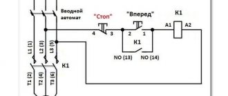
Connection diagram for a 380 V magnetic starter
Connecting to 380 V is practically no different from the first option, the only difference is in the supply voltage of the magnetic coil. In this case, power is provided using two phases L2 and L3, whereas in the first case - L3 and zero.
The diagram shows that the starter coil (5) is powered from phases L1 and L2 at a voltage of 380 V. Phase L1 is connected directly to it, and phase L2 is connected through button 2 “stop”, button 6 “start” and button 4 of the thermal relay, connected in series to each other. The principle of operation of such a circuit is as follows: After pressing the “start” button 6, through the switched on button 4 of the thermal relay, the voltage of phase L2 reaches the coil of the magnetic starter 5. The core is retracted, closing the contact group 7 to a certain load (electric motor M), and current is supplied, voltage 380 V. If the “start” is turned off, the circuit is not interrupted, the current passes through contact 3 - a movable block that closes when the core is retracted.
In the event of an accident, thermal relay 1 must be activated, its contact 4 is broken, the coil is turned off and the return springs bring the core to its original position. The contact group opens, relieving the voltage from the emergency area.
Tips for installing magnetic starters
When installing magnetic starting devices with thermal relays, it is necessary to install with a minimum difference in ambient temperatures between the electric motor and the magnetic starting device.
It is undesirable to install magnetic devices in places subject to strong shocks or vibrations, as well as near powerful electromagnetic devices whose currents exceed 150 A, since they create quite large shocks and jolts when triggered.
For normal operation of the thermal relay, the ambient temperature should not exceed 40 0 C. It is also not recommended to install it near heating elements (rheostats) and not install them in the most heated parts of the cabinet, for example at the top of the cabinet.
Comparison of magnetic and hybrid starters:
Magnetic starters
They are mainly used for starting, stopping and reversing three-phase asynchronous electric motors, however, due to their unpretentiousness, they work perfectly in remote control circuits for lighting, in control circuits for compressors, pumps, crane beams, heating furnaces, air conditioners, belt conveyors, etc. d. In short, a magnetic starter has a wide range of applications.
As such, magnetic starters are already difficult to find in stores, since they have practically been replaced by contactors
. Moreover, in terms of its design and technical characteristics, a modern contactor is no different from a magnetic starter, and they can only be distinguished by name. Therefore, when you purchase a starter in a store, be sure to specify whether it is a magnetic starter or a contactor.
We will look at the design and operation of a magnetic starter using the example of a KMI
– small-sized AC contactor for general industrial use.
Connecting a magnetic starter via a push-button post
This circuit includes additional start and stop buttons. Both “Stop” buttons are connected in the control circuit in series, and the “Start” buttons are connected in parallel. This connection allows switching with buttons from any position.
Here's another option. The circuit consists of a two-button post “Start” and “Stop” with two pairs of contacts, normally closed and open. Magnetic starter with a control coil for 220 V. The power supply for the buttons is taken from the terminal of the power contacts of the starter, number 1. The voltage approaches the “Stop” button, number 2. It passes through a normally closed contact, along the jumper to the “Start” button, number 3.
Connecting a push-button post
Let's consider 2 diagrams for connecting a contactor to a 380 V network: for a coil with a supply voltage of 380 V and 220 V.
The push-button post has two buttons. “Start” with normally open and “Stop” with normally closed contacts. Power is supplied to it (phase) through contact No. 4 of the “Stop” button. We install a jumper between terminals No. 3 “Stop” and No. 2 “Start,” thereby extending the “phase” line. Terminal A1 (phase) of the contactor is connected to contact No. 1 “Start”. The neutral conductor of the control wire is connected to terminal A2. A jumper is installed between the double contact A1 and terminal 14NO. Terminal 13NO is connected to contact No. 2 “Start”.
If the control circuit needs to be powered from one phase (phase-zero), with a starter coil rating of 220 V, the connection diagram will look like this.
When you press the “Start” button, the power contacts are activated and voltage is supplied to the block contact, which ensures the working (closed) position of the power contacts after the button is released. By pressing the “Stop” button, the circuit on the block contact is broken, and the power contacts move to the normally open position. More detailed descriptions of connecting contactors with illustrations and videos can be found on the Internet. Having done this work several times, in the future you will perform it automatically.
Source: www.scat-technology.ru
Connecting the motor via starters
Irreversible magnetic starter
If it is not necessary to change the direction of rotation of the engine, then the control circuit uses two non-fixed spring-loaded buttons: one in the normal position is open - “Start”, the other is closed - “Stop”. As a rule, they are manufactured in a single dielectric housing, and one of them is red. Such buttons usually have two pairs of contact groups - one normally open, the other closed. Their type is determined during installation work visually or using a measuring device.
The control circuit wire is connected to the first terminal of the closed contacts of the Stop button. Two wires are connected to the second terminal of this button: one goes to any of the closest open contacts of the “Start” button, the second is connected to the control contact on the magnetic starter, which is open when the coil is turned off. This open contact is connected by a short wire to the controlled terminal of the coil.
The second wire from the “Start” button is connected directly to the terminal of the retractor coil. Thus, two wires must be connected to the controlled “pull-in” terminal – “direct” and “blocking”.
At the same time, the control contact closes and, thanks to the closed “Stop” button, the control action on the retractor coil is fixed. When the Start button is released, the magnetic starter remains closed. Opening the contacts of the “Stop” button causes the electromagnetic coil to be disconnected from the phase or neutral and the electric motor is turned off.
Reversing magnetic starter
To reverse the motor, two magnetic starters and three control buttons are required. Magnetic starters are installed next to each other. For greater clarity, let’s conditionally mark their supply terminals as 1–3–5, and those to which the motor is connected as 2–4–6.
For a reversible control circuit, the starters are connected as follows: terminals 1, 3 and 5 with the corresponding numbers of the adjacent starter. And the “output” contacts are crosswise: 2 from 6, 4 from 4, 6 from 2. The wire feeding the electric motor is connected to three terminals 2, 4, 6 of any starter.
With a cross connection scheme, simultaneous operation of both starters will result in a short circuit. Therefore, the conductor of the “blocking” circuit of each starter must first pass through the closed control contact of the adjacent one, and then through the open one of its own. Then turning on the second starter will cause the first one to turn off and vice versa.
Not two, but three wires are connected to the second terminal of the closed “Stop” button: two “blocking” and one supplying the “Start” button, connected in parallel to each other. With this connection scheme, the “Stop” button turns off any of the connected starters and stops the electric motor.
MP connection diagram
A popular scheme for connecting a magnetic starter via a push-button post.
The main circuit has two parts:
Our readers recommend!
To save on electricity bills, our readers recommend the Electricity Saving Box. Monthly payments will be 30-50% less than they were before using the saver. It removes the reactive component from the network, resulting in a reduction in load and, as a consequence, current consumption. Electrical appliances consume less electricity and costs are reduced.
- Three pairs of power contacts direct electrical power to electrical equipment.
- A graphical representation of the control, which consists of a coil, buttons and additional contactors that take part in the operation of the coil or prevent erroneous activation.
The most common wiring diagram is with one device. It's the easiest thing to deal with. To connect its main parts, you need to take a three-core cable and a pair of open contactors when the device is turned off.
Scheme with connecting a 220 volt coil
Will analyze a design with a voltage of 220 volts. If the voltage is 380 volts, you need to connect a different type of phase instead of the blue zero. In this situation, black or red. In case of blocking of the contactor, the fourth pair is taken, which works with 3 power pairs. They are located at the top, but the side ones are located on the side.
Pairs of power contactors are supplied with 3 phases A, B and C from the machine. To turn on when you touch the “Start” button, it is necessary that the voltage be equal to 220 V on the core, which will help the movable contactors connect with those that are stationary. The circuit will begin to close; to disconnect it, you need to disconnect the coil.
To assemble the control circuit, you need to connect one phase directly to the core, and connect the second phase using a wire to the start contact.
From the 2nd contactor we lay 1 more wire through the contacts to the other open contact of the “Start” button. A blue jumper is also made from it for the closed contactor of the “Stop” button; a zero from the electrical supply is connected to the 2nd contactor.
Working principle
The operating principle is simple. If you press the “Start” button, its contacts begin to close and a voltage of 220 volts flows to the core - it triggers the main and side contacts and an electromagnetic flux occurs. If the button is released, the contactors of the start button open, but the device is still turned on, since zero is transmitted to the coil through the closed blocking contacts.
In order to turn off the MP, you need to break the zero by opening the contacts of the “Stop” button. Again the device will not turn on, because the zero will be broken. To turn it on again, you will need to click “Start”.
How to connect a thermal relay?
You can also make a single-line graphic drawing of the connection of a three-phase electric motor to a magnetic starter via a relay.
Between the MP and an asynchronous electric motor, a relay is connected in series, which is selected depending on the specific type of motor. This device protects the motor from breakdowns and emergency conditions (for example, when one of the three phases disappears).
The relay is connected to the output from the MP to the electric motor, electricity passes through it in a series manner through the heating of the relay to the electric motor. On top of the relay there are additional contactors, which are combined with the coil.
Relay operation
Thermal relay heaters are designed for the maximum current that passes through them. When the current rises to unsafe limits for the motor, the heaters turn off the MP.
Installation of starters inside an electrical panel
The design of the MP allows installation in the middle of the electrical panel. But there are rules that apply to all devices. To ensure high reliability of operation, it is necessary that the installation be made on an almost straight and solid plane. Moreover, it is located vertically on the wall of the electrical panel. If there is a thermal relay in the design, then it is necessary that the temperature difference between the MP and the electric motor be as small as possible.
Installation Tips and Tricks
- Before assembling the circuit, you need to free the working area from the current and check that there is no voltage with a tester.
- Set the core voltage designation which is mentioned on it and not on the starter. It can be 220 or 380 volts. If it is 220 V, phase and zero go to the coil. Voltage marked 380 means different phases. This is an important aspect, because if connected incorrectly, the core may burn out or will not fully start the necessary contactors.
- Starter button (red) You need to take one red “Stop” button with closed contacts and one black or green button with the inscription “Start” with invariably open contacts.
- Please note that power contactors only force or stop the phases, and the zeros that come and go, conductors with grounding are always combined at the terminal block, bypassing the starter. To connect a 220 Volt core to the addition, 0 is taken from the terminal block into the design of the starter organization.
You will also need a useful device - an electrician's tester, which you can easily make yourself.
{SOURCE}