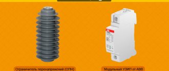
Causes of surge voltages
Household electrical appliances are made with semiconductors and microprocessors, which have poor insulation.
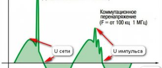
This technique can fail even with a small pulse voltage surge. Therefore, to protect electrical equipment from surge voltages, surge suppressors SPDs are used. There are several reasons for the occurrence of impulse noise. These are lightning strikes into power lines or metal structures that are located near electricity consumers. Lightning damage to lightning protection devices. Lightning discharges in clouds and nearby lightning strikes also cause electrical impulse noise in the power supply system.
Switching of large inductive and capacitive loads in energy-intensive enterprises, short circuit in the network. Even in enterprises, electromagnetic interference is created during the operation of powerful electrical installations.
3 main mistakes an electrician makes in lightning protection schemes
Removing an accidental lightning discharge from a building and eliminating the dangerous consequences of overvoltage is a complex and responsible technical task that requires:
- careful engineering calculations;
- reliable installation;
- timely preventative maintenance.
The three listed points require professional knowledge and experience, which not every specialist has.
What distinguishes a professional from other electricians is not the presence of an education diploma, the number of certificates or positive reviews, but the willingness to take full financial responsibility for the work done and the damage caused in the event of an error at any of the above stages.
Lightning protection project calculation
It must be carried out in two directions:
- external circuit for discharging current discharge;
- internal elimination of surge voltage with full consideration of local conditions.
The design calculations are influenced by the characteristics of the soil, the shape and dimensions of the building, the conditions for connecting electricity and many other factors.
They need to be calculated, modeled, tested with specialized computer programs and the necessary improvements made.
But there is another way - to collect available information yourself, for example, from the Internet and risk the safety of the house and residents: suddenly it blows over. Thunderstorms don’t happen every day, maybe... (This is what most people do, often out of ignorance.)
Installation of internal and external lightning protection
Try to answer a simple question: is it possible to produce a reliably operating system without an accurate design that takes into account emergency and operational conditions?
But this is what many home owners do. As a result, grounding loops with high electrical resistance and unreliable lightning rods are created, which turns the intended protection into a lightning trap, when the lightning rod attracts a lightning discharge, and its energy is not diverted to the ground potential, but is applied to the building.
Errors in installing internal lightning protection lead to burnout of household wiring, damage to expensive equipment, and waste of money and time.
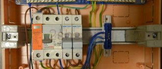
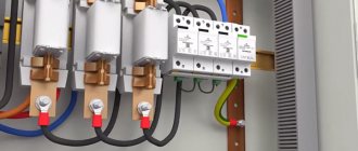
Stages of installation of surge protectors in a distribution board
Let's consider a household case when a distribution switchboard with an arrester is assembled for an apartment or a private house, a panel of the appropriate volume is selected to accommodate a meter, an input circuit breaker and individual circuit breakers in groups, an SPD of the surge arrester type for installation on a DIN rail. When all elements with the appropriate technical characteristics and wires for connection have been purchased, you can begin installation:
- On the back wall inside the control panel, a sheet plate is fastened with screws, on which DIN rails and all other elements are installed. For ease of assembly, remove this plate and mount it on a table;
- First of all, the metering unit (meter) is attached to the plate, usually in the upper left part;
- On the right side of the meter, we attach a DIN rail of the appropriate size using metal screws or bolts to install the input circuit breaker and surge arrester on it;
- On the din river in the bottom row, RCDs and circuit breakers are installed in groups;
- At the very bottom there are contact blocks with screw clamps for connecting the neutral wires and separately the ground wires;
- If there is space left in the control panel, you can install a surface-mounted socket for open wiring.
The placement of elements on the plate is not strictly regulated by governing documents; individual elements can be placed on the right or left, depending on the conditions. Practice shows that it is easier to disconnect wires from above the input circuit breaker, so a meter, an input circuit breaker, and an arrester are placed in the upper part. In the second row there are RCDs and circuit breakers in groups, at the bottom there are blocks for grounding and neutral wires. After placing all the elements, you can start connecting the wires. To disconnect the entire distribution switchboard, a detailed consideration is required in a separate topic; let’s look at where and how the surge arrester is connected:
- From the lower terminal of the output of the input circuit breaker, the phase wire is connected to the input terminal of the upper part of the surge arrester;
- If the network is three-phase, the remaining phases are connected in the same way to the corresponding terminals;
- Output from the surge arrester, the terminals at the bottom are connected by wires to the block or grounding bus;
- The neutral wire is connected to the lower terminal with the sign “N”;
One of the options for placing elements and connecting an SPD in a distribution panel
When the switching of all elements is completed, the plate is inserted into the panel housing on the wall, secured with bolts, then the phases of the incoming cable are connected to the input of the input machine, and the grounding wire is connected to the appropriate block. The wires of various groups of the power supply network are connected to the output of the corresponding machines.
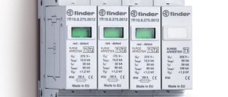
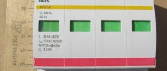
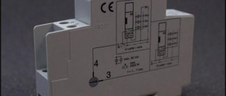
Please note that the surge arrester indicator in the initial state should be green; if it has completed its protective function, the indicator is red
Design
SPDs are manufactured to standard sizes in a modular design. Therefore, they can be easily mounted on a regular DIN rail, 35 mm wide. In accordance with the protection class, the device design can include from 1 to 4 modules. Used sections that have fulfilled their protective function are easily replaced with new ones. For this purpose, the central part of the case is equipped with special guides for new modules. Thus, replacement is quick, since there is no need to disconnect the wires and dismantle the entire device.
The main protective component is a varistor, which is a type of semiconductor. A ceramic mixture and zinc oxide are used to make it. Special impurities are added to them, creating unique locking properties of the finished element, on which the operating principle of the entire device is based. In addition, each module is separately protected from high current loads.
The front panel has a display window that shows the status and performance of the device. The conductors are connected through terminals intended for input and output. The reliability of contacts is increased due to notches, which significantly increase the contact area and reduce the resistance of the contacts themselves. When connecting wires, be sure to observe polarity. To avoid confusion, each terminal is labeled according to its purpose.
Purpose and principle of operation
The surge voltage limiter OIN-1 is needed to protect electrical networks with a voltage of 380/220V. These are standard voltages for powering electrical networks. Voltage surges can occur as a result of lightning strikes. Because of them, a potential difference arises in the ground. In addition to them, switching bursts in the network are distinguished. They occur when powerful electrical appliances are turned on or off or a group start of consumers in an electrical installation. Switching pulses can occur when starting powerful electric motors or group starting of pumping stations, as well as when turning on capacitor units.
How does the limiter work? Varistors are installed inside OIN-1. According to the principle of operation, varistors resemble arresters that were used previously. Therefore, the limiter is installed parallel to the protected circuit. If the voltage in the network exceeds the permissible (classification) voltage of the varistor, it begins to short-circuit the wires, thus diverting the danger from electrical appliances connected after it.
Kinds
Depending on the device and operating principle, SPDs are divided into several types.
Switching protective devices
Also called spark gaps. The operating principle of the spark gap is based on the use of the spark gap phenomenon. The design has an air gap in the jumper that connects each of the power lines to the ground loop. The circuit in the jumper is open at rated voltage. If a lightning discharge occurs due to overvoltage in the power line, an air gap breakdown will occur, the circuit between the phase and the ground will be closed, and the high voltage pulse will be directly grounded. The design of the valve arrester in the circuit with the spark gap provides a resistor across which the high voltage pulses are suppressed. In most cases, arresters are used in high-voltage networks.
SPD-arrester
Network surge suppressors (OSV)
These devices replace outdated, bulky arresters. To understand the principle of operation of the limiter, it is necessary to consider the characteristics of a nonlinear resistor, since the principle of operation of the arrester is based on its current-voltage function. Varistors are used as nonlinear resistors in these devices. The main material for the manufacture of varistors is zinc oxide. When mixed with other metal oxides, a component is formed that forms a pn junction with current-voltage characteristics. When the network voltage corresponds to the nominal parameter, the current in the varistor circuit is close to zero. When an overvoltage occurs in a pn junction, the current increases sharply, causing the voltage to drop to the nominal value. After standardizing the network parameters, the varistor returns to non-conducting mode without affecting the operation of the device.
You might be interested in Transformer differential protection
Limiters
Combined SPDs
Combined devices operate on the principle of a spark gap, but also have a resistor in their design. With this design, the voltage is not only grounded, but also stabilized in parallel in the main circuit.
Classes
Such devices can be divided into several categories:
- Class I. Designed to prevent direct lightning exposure. These devices must be equipped with input distribution equipment (ADS) for administrative and industrial buildings and residential apartment buildings.
- Class II. They provide protection to the distribution network against overvoltages caused by the switching process and act as secondary protection to prevent the effects of lightning strikes. They are installed and connected to the network in the panel.
- Class III. They are used to protect equipment from voltage surges caused by residual surges and asymmetrical voltage distribution between phase and neutral lines. Such devices can also operate in high-frequency interference filter mode. The most convenient thing for private houses or apartments is that they are connected and installed directly by consumers. It is especially popular to manufacture the device as a module that can be quickly mounted on a DIN rail, or in a wall outlet or plug configuration.
Diagram of the VC-122 series device
The surge and interference protection device of this series is suitable for step-down transformers. The model is also actively used in RS series shields
First of all, it is important to note that the model uses a high-voltage modulator. Its output conductivity parameter is 2 μ
The model is suitable for RS19 shields. In this case, the modulator is connected through the plate.
Filters are only allowed to be used as a pass-through type. If we look at the RS20 series shields, they have a damper. The expander for connection is used magnetic type
It is also important to note that 200 V step-down transformers cannot be used
Details Published: September 29, 2015
Here I present several typical connection diagrams for surge protection devices (SPDs). Below you will find single-phase and three-phase diagrams for different grounding systems: TN-C, TN-S and TN-CS. They are clear and understandable for the common man.
Today there are a large number of SPD manufacturers. The devices themselves come in different models, characteristics and designs. Therefore, before installing it, be sure to study the passport and connection diagram. In principle, the essence of connection for all SPDs is the same, but I still recommend reading the instructions first.
All laid out diagrams contain RCDs and group circuit breakers. I indicated them for clarity and completeness of the distribution panel. This “filling” of your shield may be completely different.
SPD connection diagram in a single-phase network of the TN-S grounding system.
This diagram shows an SPD of the Easy9 series from Schneider Electric. The following conductors are connected to it: phase, zero working and zero protective. Here it is installed immediately after the introductory machine. All contacts on any SPD are marked. Therefore, where to connect the “phase” and where to connect the “zero” can be easily determined. A green flag on the case indicates a working condition, and a red flag indicates a faulty cassette.
The presented device belongs to class 2. It alone is not capable of protecting against a direct lightning strike. Competent selection of SPDs is a complex and separate topic.
It is also recommended to protect SPD devices with fuses.
I think everything is clear here.
Below is a similar diagram for connecting an SPD, but without an electric meter and using a common RCD.
SPD connection diagram in a three-phase network of the TN-S grounding system.
The diagram also shows an SPD manufactured by Schneider Electric of the Easy9 series, but for a 3-phase network. The figure shows a 4-pole device with a neutral working conductor connected.
There is also a 3-pole SPD of the same series. It is used in the TN-C grounding system. It does not have a contact for connecting the neutral working conductor.
SPD connection diagram in a three-phase network of the TN-C grounding system.
The SPD from IEK is shown here. This diagram is a regular input panel for a private house. It consists of an input circuit breaker, an electric meter, an SPD and a general fire protection RCD. The diagram also shows the transition from the TN-C to TN-CS grounding system, which is required by modern standards.
The first picture shows a 4-pole input circuit breaker, and the second picture shows a 3-pole one.
There is no more permanent connection than a temporary twist!
This is where you need to be very careful. Incorrect selection of a circuit breaker according to its rating can lead to a fire in the wiring or the machine will trip five times.
A circuit breaker has tripped in your apartment panel. As a result, some part of the apartment lost power. Almost everyone has found themselves in this situation. What are your next steps?
Light bulbs have burned out, are burning out and will continue to burn out, otherwise it is not profitable to produce them. Just think about it: a factory produced one light bulb, a person bought it, screwed it in at home and it works as expected.
Cables and wires play one of the most important roles in powering your home. An incorrect choice of cross-section can lead to overheating of the insulation, its breakdown, short circuit and serious problems.
Friends, respect the work of others and when copying materials, please put an open link to the source sam-sebe-electric.ru, otherwise I will turn off the light. |
Electrical panel diagram with SPD
The circuit diagram of a distribution board that is well-equipped from the point of view of protection against all voltage surges and surges should look something like this.
At the input in front of the meter there is an input circuit breaker that protects the metering device and the circuits inside the panel itself. Next is the counter.
Between the meter and the input machine there is an SPD with its own protection. The electricity supply organization can, of course, prohibit such installation. But you can justify this by the need for surge protection for the meter itself.
In this case, it will be necessary to mount the entire circuit with the devices in a separate box under a seal in order to prevent free access to exposed live parts up to the meter.
However, here the issue of replacing the triggered module and breaking the seals will arise. Therefore, agree on all these points in advance.
After the metering device there are:
voltage relay UZM-51 or equivalent
RCD 100-300mA – fire protection
RCDs or differential circuit breakers 10-30mA - protecting people from leakage currents
simple modular machines
If there are no questions with the usual components when assembling such a shield, then what should you pay attention to when choosing an SPD?
For operating temperature. Most electronic types are designed to operate at ambient temperatures down to -25C. Therefore, it is not recommended to install them in street shields.
The second important point is the connection diagrams. Manufacturers may produce different models to suit different grounding systems.
For example, it will no longer be possible to use the same SPDs for TN-C or TT and TN-S systems. You will not achieve correct operation from such devices.
Connection of SPD according to degree of protection
Each device with individual protective properties has its own SPD connection diagram.
- 1st degree devices are installed in panels of the RV series. Direct connection is made using a transceiver. The average output voltage is 14 volts. Conductivity may vary according to the type of resistors used. An amplifier is used together with them. The threshold conductivity is on average 4.5 microns. Before starting the connection, you need to check the total resistance of the circuit. It should be 50 ohms. These devices are not suitable for other types of shields due to their high current conductivity.
- Devices of the 2nd degree are used in the PP series panel. Here, the SPD connection diagram dispenses with transceivers and all connections are made only with conductors. Before connecting, the parameters of the output voltage on the stabilizer are also checked, which is approximately 13 volts. During operation, two-pin extenders are used. Insulators are installed in the PP20 panels, and the SPD is connected via a grid triode with an operational amplifier. PP21 panels are equipped with integrated rectifiers involved in current conversion.
- SPDs of the 3rd degree are designed for installation in panels equipped with a feed-through dinistor. A damper is used to connect equipment. The connecting contacts have a copper lining. The total circuit resistance does not exceed 40 Ohms. In PP19 panels, the thyristor is installed together with the amplifier. Some modifications use capacitor resistors. It is possible to connect the device together with an adapter.
Preparing for work
Choosing and purchasing a voltage stabilizer for your home is only the initial stage that you will have to face if you decide to protect your household appliances from emergency situations in the electrical network. The next step should be to find an answer to the question - how to connect and install a voltage stabilizer?
connect the stabilizer to your home network
So, before starting installation work, you need to remove the device from the packaging and inspect it for possible mechanical damage. If the stabilizer has been at a negative temperature for a long time (during transportation), it should be kept for at least 2 hours before connecting it to the network. This will avoid the appearance of condensation when the equipment heats up during operation.
Next we move on to the question of how to install a voltage stabilizer for the home? The equipment may be installed indoors, where it will not be exposed to construction dust or other aggressive environments. There should be no flammable materials near the stabilizer.
Watch the video, connection steps:
https://youtube.com/watch?v=gsmqpvq0YFM
The device body must be grounded, and the connection to the network is made through the corresponding pair of terminals located on the rear panel. The stabilizer is turned on using a circuit breaker; the voltmeter should show 220 V. A load is connected to the output terminals and only after that can the switch be turned on.
How to calculate stabilizer power
To choose the right model, you need to decide which electrical appliances will be connected to the device. You can determine their power consumption using one of the methods provided on the Internet or use the simplest of them. It is as follows. There is a circuit breaker on the electrical panel, the rating of which is selected in such a way as to protect the wiring from damage due to overload.
Watch the video to correctly calculate the power of the device:
But how to calculate the power of a voltage stabilizer for your home? From the physics course we know that this parameter is equal to the product of current and voltage. The values of these quantities are easy to determine. The voltage in a single-phase network is 220V, and the rated current is usually indicated on the circuit breaker. Let's say it is 16A, then the power will be 16*220=3520 W. But you need to choose a stabilizer with a margin of at least 30%. This is due to the fact that as the voltage increases, the output power drops.
Device malfunctions and their solutions
Possible options for equipment failure are usually given in the documentation supplied with it. Among them, the following malfunctions most often occur:
- Spontaneous shutdown of the device usually occurs due to exceeding the permissible load;
- The network indicator light does not light up if the device is not connected, the fuse is faulty or the connections are mixed up;
- It is not possible to achieve an output voltage of 220 V with an unacceptable load;
- There is no stabilization - this may be due to problems with the input-output button or turning off the Bypass mode.
Expert advice
Many consumers are interested in the answer to this question. Those who believe that this can increase the power of the stabilizer are mistaken. On the contrary, the output parameters will correspond to the value produced by the weakest device in the network. For example, if three devices of 5;10;15 kW were connected in parallel, then the output power will be only 5 kW, since this figure is the lowest.
SPD protection classes
The classification of these protective devices is made in accordance with GOST R 51992-20111.
GOST defines the following classes of these devices:
- 1st class or "B". These devices protect against the direct effects of lightning when lightning strikes enter the system. They also neutralize atmospheric and communication overvoltages. For installation, a connection diagram is used from the input to the facility where the main switchboard and ASU are installed. Class 1 devices are primarily used for buildings located separately in open space or connected to overhead power lines. Other connection factors include neighboring houses equipped with lightning rods or tall trees located nearby. The value of the rated discharge current is in the range of 30-60 kA.
- 2nd class or "C". These devices neutralize the remnants of atmospheric and switching overvoltages that have overcome class 1 protection. The installation location, including for UZM, is the usual input panels of an apartment, house or office. The discharge current rating is 20-40 kA.
- 3rd grade or "D". Protect electronic equipment from residual high voltages and high-frequency interference missed by class 2 protection. An example is a surge protector to which a computer is connected. Withstands discharge current from 5 to 10 kA. Using devices of all three classes, single-line multi-stage protection is created.
SPD as an element of internal lightning protection
Lightning is one of the natural phenomena. Its sudden action leads to severe destruction of the object itself and all electronics located indoors. The main safety measures are assigned to external lightning protection. This is a whole system that includes a lightning rod located on the roof, connected to a lightning rod and a grounding loop.
The current that occurs at the moment of discharge is a short-term high-voltage pulse that easily enters the operating network in the absence of internal protection. Under its influence, strong overvoltages are induced in all wiring located inside the building, burning the insulation and destroying the electronics of household appliances.
To prevent such situations and their severe consequences, an internal lightning protection connection diagram is provided. They are equipped with technical devices and instruments used in a complex. The basis is SPD modules - surge protection devices connected to grounding systems, or SPD. Inside the building they perform the following protective functions:
- Neutralizes the effects of lightning discharges that fall directly into the house.
- They dampen impulses generated when lightning strikes the power lines supplying the house.
- Prevents the consequences of impacts on tall trees and nearby buildings.
- The same actions are performed when lightning strikes the ground near the house.
It is the last two options that cause the impulse to penetrate into the building through the grounding loop, water supply and sewer pipes. If there is internal protection, it is triggered instantly, transferring the pulse to varistors or special arresters that neutralize high voltage.
SPD classes
Class I (B). Devices belonging to this class protect against direct lightning strikes into the lightning protection system of a building or overhead power grids. Installation of these devices is carried out directly in the ASU or main switchboard where the cable enters the building. These devices are designed for a discharge current of about 30-60 kiloamperes.
Second class (C). These devices are designed to protect power distribution networks of objects from switching interference. They are capable of functioning as a second protective stage against lightning strikes. They are installed in the switchboard, and their discharge current is rated at 20-40 kiloamperes.
Class III (D). Blocks, which are protective devices of this class, are installed directly in front of the consumer device. Such devices can be very different in design (socket, plug, separately mounted module, or wall-mounted device). Their discharge current does not exceed 5-10 kA.
The main element in the construction of such devices was a varistor or arrester. In addition, these devices include an indicator device that can indicate that the SPD has failed.
One of the negative indicators of these “defenders” is that they heat up when activated, which is the reason that they need time to cool down, and this greatly reduces the selectivity of the device.
Such a device is mounted on a DIN rail. A varistor that has failed can be easily changed by removing the latter from the housing.
To achieve good quality consumer protection from unnecessary influences, it is necessary to provide buildings with effective grounding systems and potential equalization. For this purpose, a grounding system of the TN-C or TN-CS type is used, which has separation of the neutral and protection conductors.
Then protection devices are installed, the distance between which (from one class to another) should not be less than 10 meters along the power cable. Only if such conditions are met can the correct operation of the protective devices be ensured.
On overhead lines and in input panels on poles, systems based on arresters and fuse-links work best.
The main switchboards of buildings are well protected by SPDs of the first and second class, based on varistors, and floor switchboards are equipped with systems of the third class. As additional protection, sockets are equipped with systems in the form of inserts and various extension cords.
Finally, I would like to note that devices of this type significantly reduce the percentage of consumer failures and human injury from high voltage, although they are not able to fully provide one hundred percent protection. Therefore, during a thunderstorm, you should, if possible, disconnect the most important consumers from the power supply.
Write comments, additions to the article, maybe I missed something. Check out the site map. I will be glad if you find anything else useful on my site. All the best.
Operating principle of the device
The operating principle of the protective device is quite simple. Typically, a surge protector can eliminate an overvoltage instantly. This is a simple voltage tapping circuit. For example, if the voltage is normal, then the resistance of the varistor will be determined by megaohms. If an overvoltage appears on the line, then the varistor moves to the cable category. An electric current passes through the conductor and flows to ground.
How does a voltage limiter work?
For your information! The operating principle of SPDs is classified into two categories: valve/spark arresters. They are usually used for high voltage networks, like protective devices with varistors.
When the action of a lightning discharge during overvoltage is detected in the arresters, then this can break through the air passage in the jumper that connects the phases to the ground loop. A high voltage pulse hits the ground. In the case of valve-type arresters, the reduction of the high-voltage pulse in the circuit with the spark gap occurs through a resistor.
SPDs in gas-filled arresters are suitable for buildings where an external lightning protection system or electricity supply occurs through the air due to special lines.
Equipment with a varistor is connected in parallel with the protected device. In the absence of pulse voltage, the current flowing through the varistor is almost zero. However, when an overvoltage occurs, the resistance of the equipment drops sharply, it allows current to pass, dissipating the absorbed energy, causing the voltage to drop to its nominal value. Thus the varistor returns to non-conducting mode.
The SPD has built-in thermal protection, which prevents burnout at the end of its service life. However, over time, the device breaks down and the voltage limiter needs to be replaced. The indicator itself informs about problems.
You may be interested in this Features of a single-phase electric meter
Important Note
We looked at why OIN-1 is needed and how to install it. But it is imperative to add a note from the official documentation:
We are talking about connecting the machine to the break in the supply wire in front of the limiter. This is necessary in order to break the circuits in the event of a short circuit in the pulse limiter and prevent the negative consequences of the event.
Finally, we recommend watching a video that clearly explains how to connect a surge voltage limiter to the network:
This is where we finish the description of the characteristics and rules for connecting OIN-1. We hope that the prepared review was useful and interesting for you!
You probably don't know:
Technical characteristics of SPD
These include:
The surge waveform is standardized for the following cases:
- direct lightning strike – 10/350 µs;
- exposure to indirect lightning – 8/20 µs.
Pulse shape 8/20 µsPulse shape 10/350 µs
According to their intended purpose, according to the IEC standard, SPDs are divided into types 1-3; according to GOST R 51992-2002, they are divided into test classes (I – III). The correspondence and purpose of these characteristics are indicated in the table.
| Types according to IEC 61643 | Classes according to GOST R 51992-2002 | Purpose | Installation location |
| 1 | I | To limit overvoltages from direct lightning strikes | At the entrance to the building, in the main distribution board |
| 2 | II | To limit overvoltages from distant lightning strikes and switching overvoltages | On entries where there is no danger of direct impacts |
| 1+2 | I+II | The characteristics of SPD types 1 and 2 are combined | Same as type 1 or 2 |
| 3 | III | To protect sensitive consumers. Have the lowest level of protective voltage | For direct installation at consumers |
According to their design, SPDs are produced with a different number of poles: from one to four.
How to determine the type of grounding system
To determine the type of grounding system, you need to consider the PEN conductors, that is, how they are separated. If everything is ready, the wiring is similar to the TN-CS system. In this case, for a three-phase circuit, five main wires come from the main distribution panel of the house, but for a single-phase circuit, only three wires are used. PEN conductors are divided into two components: PE and N.
Note! If it is not split, the wiring will work according to the TN-C system, with 4 wires from the three-phase system and 2 wires from the single-phase system coming from the distribution panel.
Based on the principles described, the type of grounding system can be easily determined. In all cases when the TN-C system is used in private homes, it is recommended to transfer it to the TN-CS scheme, which is more promising and safer.
You may be interested in the principle of operation of a constant voltage generator
How to calculate a grounding system
Surge protection devices SPD: application, connection diagram, operating principle
During a thunderstorm, impulse noise often occurs in the network. They can also be observed when a transformer breaks down. To protect electrical equipment in the house, special SPD devices are used. They are installed in shields of different configurations.
The difference between the modifications lies in the parameters of the output voltage, threshold frequency and conductivity. The standard model consists of a block and contacts. Resistors are installed in various types. The modulator in the devices is connected to the transceiver. This element contains conductors and a triode. In order to learn more about SPDs, you should consider the operating principle of the model.
How does the SPD work?
The operating principle of SPDs is based on the use of special elements - semiconductor varistors. Their resistance is nonlinearly dependent on the applied voltage. That is, when the voltage increases and exceeds a certain value, the resistance of the varistor will be sharply reduced.
In normal operating mode, the voltage is within 220 volts, and the resistance of the varistor installed in the SPD or UZM is very high during this period, up to several thousand megohms. Thus, the varistor has practically zero conductivity and does not allow electric current to pass through it.
Devices of the TESSLA D32 series
Devices of this series are manufactured with pass-through modulators. Their contacts are of the movable type. For PP20 series shields, this device is often used. The modulator is connected via an expander. It is most often used with a converter. To solve problems with increasing frequency, a tetrode is installed.
If we consider the shields of the PP10 series, then they have a kenotron. The specified element is installed on two or three outputs. In the first option, the device modulator is connected via a damper. Its output conductivity parameter is 3.3 microns. The total resistance in the circuit is 30 ohms. If we consider the second option, then the SPD will require a dinistor.
Regulatory basis for the use of SPDs
What is an SPD? The main Russian document defining what an SPD is is GOST R 51992-2002 “Devices for protection against surges in low-voltage power distribution systems.”
According to this GOST, “Device for surge protection (SPD): a device that is designed to limit transient overvoltages and drain current pulses. This device contains at least one nonlinear element." The standard applies to devices for protecting electrical networks and electrical equipment under direct or indirect influence of lightning or other transient overvoltages. These devices are designed for connection to AC power circuits with a frequency of 50-60 Hz for a rated voltage of up to 1000V (rms value) or 1500V DC.
Depending on the test class, SPDs are divided into 3 types.
Class I tests are designed to simulate partially directed lightning current pulses. SPDs subjected to such tests are recommended for installation on linear inputs into buildings protected by lightning protection systems, as well as for air supply input. A characteristic feature of this class is the pulsed current test Iimp with a waveform of 10/350 µs (1). The most important parameter characterizing the SPD is the protection voltage level Up, which is measured at In. This is “a parameter characterizing the SPD in terms of limiting the voltage at its terminals, which is selected from among the preferred values.” Its value is always higher than the residual voltage Ures, i.e. peak value appearing at the terminals of the SPD due to the passage of a discharge current of a given amplitude. Up should not exceed the resistance of electrical equipment to impulse voltage, defined in GOST R 50571.19-2000. Therefore, it is accepted that for a class 1 SPD Up does not exceed 4 kV.
Standard test pulse
Class II tests are designed to simulate a pulse induced in conductors by an electromagnetic field. SPDs subjected to such tests (2nd class SPDs) are intended for installation after 1st class SPDs in intermediate cabinets, or in the incoming cabinet, if there is no likelihood of part of the direct lightning current entering the power supply system. Tests are carried out with the rated discharge current In and the maximum discharge current Imax. Both pulses have a waveform of 8/20 µs, but different amplitudes. In this case, Imax > In. The SPD must withstand the In pulse multiple times, provided that it cools to room temperature in the interval between pulses. Typically, the number of withstand pulses is from 5 to 15 (according to GOST, the number is not established and is determined by the manufacturer, according to IEC - 15 pulses). The SPD must withstand the Imax pulse once, while its further operation in accordance with the declared parameters is not guaranteed (but possible). The protection voltage level Up for class 2 devices should not exceed 2.5 kV.
Class III tests also simulate an induced pulse, but are tested with a combined 1.2/50 µs voltage and 8/20 µs current waveform. In this case, the parameters indicate the open circuit voltage Uoc and the rated In and maximum Imax currents. The protection voltage level Up for class 3 should not exceed 1.5 kV. This is the level that equipment must withstand, even if it has not been tested for resistance to microsecond pulse overvoltages. Therefore, it is recommended to use these devices in close proximity to the protected equipment (preferably no further than 5-7 meters, but in general, the closer, the better).
A few more important parameters that you need to know to select an SPD.
The maximum long-term operating voltage Uc is the effective value of alternating or direct current, which is continuously supplied to the terminals of the SPD. It is equal to the rated voltage, taking into account the possible overestimation of voltage under various abnormal network operating conditions.
Rated load current IL is the maximum continuous alternating (rms value) or direct current that can be supplied to the load protected by the SPD. This parameter is important for SPDs connected to the network in series with the protected equipment. Since most SPDs are connected in parallel to the circuit, this parameter is not indicated.
Characteristics and markings
Each protective device of one class or another has individual parameters that are taken into account when connecting an SPD. The main technical characteristics are applied to the product body, and full information is reflected in the passport. When choosing a device, you must first pay attention to the designation and the following indicators:
- The nominal and maximum voltages at which the device can operate normally for a specified time.
- An indicator of the operating frequency of the current for which the SPD is calculated.
- The value of the rated discharge current. Next to the numbers the shape of its wave is indicated. It is a current pulse with a wave of 8/20 ms, expressed in kA, passed through the device repeatedly, without any consequences.
- The value of the maximum discharge current that the protection passes once without losing its overall performance.
- The protection voltage level indicates the device's overvoltage limiting capabilities.
Connection diagrams
To protect low-voltage networks, there are several schemes for connecting SPDs. The ideal option is the integrated use of devices, since lightning strikes are absolutely not predictable.
External system
The external protection element is taken on the basis that the maximum current can flow through its components. The protective device is installed with the ability to withstand 100 kA. To prevent a negative impulse from causing a lot of trouble, it should be diverted along the path of least resistance.
For this purpose, a complex surge protection device is installed in the electrical panel, which includes three degrees of protection. This device has high power and response speed, protecting equipment with a total power of up to 20 kW.
If this is grounding divided into two sections, then two separate buses are mounted in the panel: zero, grounding. A jumper is installed between them, which is considered additional protection.
Installing branch protection
It is possible to install an SPD not in the distribution panel, but directly on a branch of the electrical network. For example, where an overhead line diverges into two neighboring houses, and the ground loop does not have lightning rods.
Sometimes the device is installed at the entrance to the house and the use of an SPD with protection class 3 is irrational. Devices of class 1 and 2 are installed. If the distance from the pole to the house exceeds 60 m, then an additional device with protection class 2 is installed in the electrical panel.
The method of installing protection differs if the house is connected to an underground cable. An emergency situation arises from other external sources, so the duration of impulse noise will be much shorter. For protection, it will be enough to install a class 2 SPD into the distribution board.
In addition to electrical lines, overvoltage can occur in television networks. Often high-voltage interference is generated at antenna receivers in houses where there are no lightning rods. The occurrence of a short-term high voltage in the antenna cable leads to failure of the TV selector.
The protection device is an antenna adapter with a grounding device. There are two types of devices: for analogue, satellite or digital television. They can be distinguished by the corresponding inscriptions on the case: Radio/TV, SAT.
The importance of the protected equipment
Protected objects are divided into several classes. These are those that harm external factors, human life, and also animals.
These include:
- chemical and petrochemical industry facilities;
- biochemical and bacteriological centers;
- explosives factories;
- nuclear power plant.
Device Features
The reliability of protection against lightning strikes in these enterprises reaches 0.98 (for individual items in Category A zones it can be set at a higher level of 0.995). This phenomenon can cause negative effects, for example:
- fire;
- explosion;
- releases of toxic substances;
- increased radiation at large objects;
- an environmental disaster resulting in material or human damage.
There are other objects that can have a negative impact on the environment:
- oil refining enterprise;
- gas station;
- flour mill;
- woodworking companies;
- enterprises producing plastic products.
The reliability of protection for these objects must be no lower than 0.95. The negative impact of lightning strikes is fires, explosions in and around the area. Walls and ceilings can collapse, causing serious injury or even death to employees. In addition, this will entail significant financial losses.
There are also objects belonging to special critical infrastructure. We are talking about communications and ICT enterprises, pipeline transport, power lines, central heating equipment, and transport infrastructure. The reliability of impact protection on them is 0.9. Negative consequences of lightning strikes:
- communication breakdown;
- partial or complete loss of control;
- failure of the heating system;
- temporary decrease in quality of life and loss of material.
The last category includes general, industrial and civil facilities and associated infrastructure:
- residential buildings;
- industrial buildings (up to 60 m high);
- houses in villages;
- objects of social and cultural significance;
- educational establishments;
- hospitals and museums;
- temples, churches.
The guarantee against lightning strikes on them is 0.8. Negative consequences of lightning strikes: severe fires, damage to buildings, disruption of traffic, communication systems, possible loss of historical and cultural heritage, significant material and financial losses.
What are the risks?
Note! Connecting SPDs of various classes together with a grounding system reduces the risk of equipment breakdown due to a power surge or lightning strike by 99%