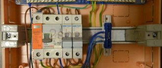
We continue the topic of modern protection devices for home electrical panels. Next in line are Arc Fault Protection Devices (APD - wording from GOST), aka “Arc-fault detection devices” (USIS), aka arc-fault detection device (AFDD), aka arc-fault circuit interrupter (AFCI)... There are many names , but the essence is the same: this device is designed to disconnect the line if an arc breakdown is detected somewhere on the line. This is the theoretical and methodological part. Tests and dissection of devices will continue.
This article has a video version for those who prefer to listen:
▍ Hot little thing
Let's imagine something wrong happened in your electrical wiring - mice chewed the insulation, a terminal came loose, or wires broke where the cable was bent.
These, as well as a number of other faults, can lead to arc breakdown. An arc breakdown occurs when two conductors are at a very short distance from each other, which causes a spark to jump, an electric arc to ignite, and the electric current to flow through the air. An electric arc is very hot, and in moments it can ignite flammable materials around it, char the insulation and cause disaster. Moreover, the charred insulation becomes a conductor, which greatly simplifies the re-ignition of the arc.
A distinction is made between parallel and sequential arc breakdown. Parallel arc breakdown - when an arc ignites between conductors L and N or L and PE, for example, due to a self-tapping screw screwed into the cable. Or, for example, it begins to break through damaged insulation. In this case, most likely, the parallel arc breakdown will develop into a short circuit and the overcurrent protection will operate. Sequential arc breakdown, when the arc burns in an open circuit in series with the load, is the most dangerous. Neither the RCD nor the circuit breaker will work! There are no conditions for these types of protection to operate - the current is not exceeded (its value is limited by the load), and there is no differential current either. The arc will burn until contact is accidentally restored or broken. However, you’ve probably already encountered it - this is the same “crinkling” of a bad contact in a switch or socket.
If your wiring is done in strict accordance with all standards, then an arc breakdown will not cause a fire, but will generate streams of abuse from the electrician who will be repairing the outlet, where two charred stumps of wires are sticking out of the socket.
The key word here is “if”. Unfortunately, the harsh reality may be:
- Old aluminum wiring, which was repaired, I don’t understand how and I don’t understand where
- Wiring laid inside combustible walls
- Rodents that have eaten wire insulation down to bare copper
- Unfortunate builders who damaged the insulation of wires with a self-tapping screw
- A huge number of carriers, tees and other electrical products of dubious quality, lying in hard-to-reach places surrounded by flammable objects
In an unfortunate combination of circumstances, an arc breakdown can cause a fire, resulting in casualties.
It turns out: with a careless attitude towards electrical maintenance, we can get a phenomenon that can lead to a fire, and which none of the protective equipment used can detect. Sounds unacceptable.
Causes of fires and protection against them
Modern apartment electrical panels use many devices that are designed to increase safety.
- Automatic devices (circuit breakers) disconnect the consumer in the event of a short circuit or overload.
- Automatic devices disconnect the consumer in the same cases as automatic machines, but also when a current leak occurs, thereby protecting a person from electric shock.
- The RCD switches off in the event of a leak, but is only used in conjunction with a separate circuit breaker, since it is not built into it.
- Recently, a voltage relay began to be installed en masse in the panel, which monitors the voltage and turns off the consumer when the voltage goes beyond the established limits, thereby saving equipment from breakdown.
Not long ago, a new type of device was invented to minimize the possibility of a fire. They will be discussed further.
If you think about and analyze why a fire can occur, it turns out that most of it occurs due to a fault in the electrical wiring. Let's try to list all possible fire situations involving electricity:
- forgotten iron
- improper operation or malfunction of electric heating devices
- short circuit or wiring overload, but only if the machine for some reason did not work or worked late.
- voltage surges in the power supply network, which can cause malfunctions of household appliances, for example, breakdown of the insulation of filter capacitors, and as a result, a fire.
Sparking, also known as an electric arc, can occur due to various insulation faults or poor contact in connections. Heating and charring of insulation in places of poor contact and increased resistance causes charring of the insulation; charred insulation reduces its resistance, which further aggravates the heating effect. Thus, the charred parts of the insulation may begin to conduct current, followed by an avalanche-like increase in this process and the occurrence of an arc, which can cause a fire. In the first and second cases, the manufacturers of household appliances themselves take measures to eliminate the possibility of fire by installing all kinds of safety systems in them.
In more expensive irons, for example, they install a position and motion sensor that will turn off the iron in a horizontal position without movement in less than a minute, and in a vertical position without movement in a few minutes, which eliminates the human factor. For those who are forgetful, I recommend looking for just such an iron on sale.
Heaters usually have several overheating sensors and a sensor that monitors the correct operating position, namely a button that turns off the device when it tips over.
In case of overvoltage in the network, a voltage relay helps. It is triggered by increased voltage or a power surge.
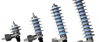
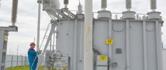
For private homes, protection against power surges during thunderstorms is especially important. This voltage surge can be significant. For complete protection, varistor protection will help - OPS1-D or similar. A varistor absorbs energy during a voltage surge.
▍ Catching the ghost by the tail
Engineers are still searching for a reliable way to detect arc faults; if you look through publications in scientific journals, you can see attempts by researchers to use different techniques, including fashionable neural networks.
The better the technique, the higher the probability of detecting an arc breakdown and the lower the number of false alarms: In this case, the device in the electrical panel has only one way to detect an arc breakdown - analyze the magnitude and shape of the current supplied to the load. All manufacturers of modular arc flash protection devices collect a signal from a current sensor, but process the data differently and do not disclose details, citing know-how. Therefore, I can only tell you the general approaches that are disclosed in scientific publications, but in the hunt for details you will have to catch and solder the developers in a pub.
It is still possible to detect an arc breakdown due to one feature - the arc does not ignite immediately. The voltage must rise to the breakdown voltage, after which a spark jumps in the gap, which ionizes the air and allows the electric arc to ignite steadily. And since we have alternating current in our network, and the current changes direction 50 times per second, passing through zero, the arc lights up and goes out 100 times per second, leading to specific distortions!
I’ll show you with examples why I made a small stand. I measure the current in the circuit with a current transformer (blue line), voltage - through a divider (yellow line), the scale in this case is not important. Almost ideal load - fan heater:
It’s simple: as the voltage in the line increases, the current increases proportionally. The voltage drops - the current in the circuit drops. Pay attention at the point where the voltage crosses zero - the current increases immediately. And this is what the current looks like in the same circuit if I separate the contacts and cause an arc breakdown in series in the circuit. A step appears - the current appears only after the voltage reaches the breakdown voltage of the gap between the conductors:
You might think that it is enough to simply monitor whether there is a step in current consumption when the voltage passes through zero. But alas, this method does not work, since such a step appears in many types of load. For example, if the device has power regulation with a thyristor regulator, which creates such a step and, by changing its width, regulates the power in the load. Just look at what the current graph looks like for a vacuum cleaner with a power regulator:
In addition, the ideal case of only one load on the line is rare. More often there are several consumers on the line, and their currents are summed up. As a result, the graph begins to look completely unclear. The graph below shows four consumers (1 kW heater, 2 kW electric kettle, vacuum cleaner with a regulator at half power (approximately 800 W) and a powerful switching power supply loaded with ballast (approximately 180 W)). On the left there is no arc breakdown, and on the right there is a sequential arc breakdown of a 1 kW heater, i.e. The arc current is only a quarter of the total current consumption:
What to do? Let's look carefully at the graph with sparking - the rate of current increase in the circuit after a breakdown is enormous, the step is almost vertical! This means we need to look not at the appearance of the step, but at its verticality. The easiest way to do this is by analyzing the spectrum of the signal; the steeper the step, the wider its spectrum. I visually depicted it in this picture:
As a result, the principle of operation of the protection is simple - we constantly analyze the spectrum of the signal from the current sensor. If suddenly it changes dramatically, we determine how it changed. If we observe a rise in the high-frequency part of the spectrum, this means an arc breakdown and we turn off the load. True, in reality there are nuances...
Arc protection device: how modern modules work
The design is based on the technology of digital recorders, when the period of high-frequency pulses of a calibrated generator is used to form the time for measuring the effective values of current or voltage.
Signals are received from the corresponding built-in sensors and processed by the controller according to specified algorithms. Manufacturers do not disclose their technologies, but the results can be judged by the technical characteristics.
The arc protection device operates on the principle of continuously scanning the current spectrum within the controlled area. When a spark occurs in it, the microcontroller instantly assesses the possibility of it causing harm and makes a decision to turn it off or ignore it.
The most valuable thing in this algorithm is the ability of the microcontroller to distinguish sparks created by commutator motors of household appliances and, for example, welding machines, from wiring damage.
Programs are created for it, microcircuits and final modules are manufactured.
Let's analyze them for indirect reasons that manufacturers publish as output parameters. Let's look at several modules.
S-ARC1: ABB technical specifications with manufacturer's video
Arc protection against ABB, implemented in the S-ARC1 module, is shown in the middle part of the picture. For clarity, its characteristics have been enlarged and placed on the left. Red arrows indicate the most important parameters.
On the right is the appearance of the DS201 differential machine from the same manufacturer. The pictures were taken from different angles, but they allow us to judge the similarity of the cases and methods of connecting wires.
The markings on the phase terminal 1/2 at the top and 2/1 at the bottom indicate that the wires can be inserted from any direction, as is convenient for the installer. The voltage supply side does not affect the operation of the protection.
This takes into account the unspoken rules that in the West they try to install all the wiring from below, while in our country we have adopted top installation.
Standard terminal clamps allow the use of mounting combs, which eliminates the need for conventional jumper wires, saving space and simplifying work.
The lower left arrow indicates the operation of the module using digital technology with an electronic circuit. Next comes the inscription: B16, like the circuit breaker - time-current characteristic B and rated current (16 amperes).
For information: I looked for arc short circuit protection modules for high rated currents. They are all designed to operate between 10-40 amps. I was unable to find the above from foreign manufacturers.
Based on the time-current characteristics and rated current, it is convenient to select S-ARC1 for a specific circuit breaker.
The inscriptions in rectangles 6000 and 3 indicate that the switching capacity of the contacts is capable of breaking emergency currents up to 6 kA, and the current limiting class is No. 3 (the fastest).
There are many module designs that can reliably break large emergency currents - 10 kiloamperes.
On the Eaton Corporation website I found this current-voltage characteristic B and C of the arc protection of AFDD+ modules.
I suggest comparing it with the characteristics of a circuit breaker.
As you can see, they have a lot in common. For AFDD, the shutdown parameters are shown in seven positions on the characteristics. See and compare for yourself.
The operation of ABB S-ARC1 modules is shown in a one and a half minute video from the company. Those who do not understand German speech can watch without sound.
Pay attention to the moment the protection is turned off. It does not work immediately, but turns off the power after the wiring starts to catch fire. These settings were chosen specifically to increase reliability.
UZM 51MD: fire protection device from the Meander company in St. Petersburg
The domestic manufacturer has already released many of its own modules, which differ in their operating algorithm and characteristics. The general model was the UZM-50M relay.
I show the latest developments UZM-50MD and UZM-51MD with the characteristics that interested me with a picture with red arrows.
Meander emphasizes with an inscription on the front side of the case that they are designed to operate in a network under voltage of 230 volts with a frequency of 50 hertz and cannot be used as disconnectors.
However, three other quantities were more interesting:
- Increased rated current compared to AFDD up to 63 A.
- Reduced switching capacity of contacts to break emergency currents up to 4.5 kA.
- Strict dependence of the direction of voltage supply. The entrance is located at the top and the exit is at the bottom. Wires cannot be swapped.
According to these three indicators, the defense is inferior to its foreign counterparts.
Meander published a schematic diagram of the UZM-51MD device, used to connect phase and neutral wires.
It shows that this protection monitors the state of the input voltage and, if the parameters deviate from the setpoint, disconnects it from the load.
Of interest is the operation diagram of the UZM 51MD, showing the upper and lower voltage limit levels, accelerated and delayed shutdown zones.
The diagram with response time parameters was taken from the manufacturer’s website.
UZIS: anti-sparking device from Ecolight - what you didn’t like and is repellent
The leading domestic manufacturer of LED technology has also released a protection module with specific characteristics.
On the right in the picture you can immediately see that the voltage supply is made from below and the output from above, which contradicts our generally accepted installation rules.
The rated current of the module is 40 amperes, and the network voltage is 230 volts. It is possible to limit the upper limit to 290. Directly on the box are operating conditions and technical specifications.
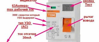
The “Test” fork is also included there. Its purpose is to check the serviceability of the built-in electronics by connecting it to a power outlet. (Strange design: it cannot be stored in an outlet, and due to its small dimensions it is easy to lose.)
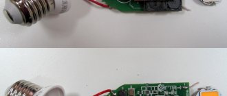
The module components removed from the housing are shown in the picture below.
It is clearly visible that the working zero line is not broken and is made in one piece. The microprocessor and other electronic components are clearly visible on the electronic board.
Surge protection is assigned to the varistor. Its body is not closed. This means that when triggered, it can explode, and fragments will scatter inside the circuit.
The photo of the power section shows a ring-shaped measuring current transformer, a powerful switching contact and an electromagnet.
I immediately remember the declared value of the rated current: 40A. The rupture of such a load without the formation of an electric arc does not occur. It will need to be repaid. The arc suppression chamber is not visible: absent.
The switching capacity of the contacts is not indicated, and even Meander announced his module - 4500.
These are the thoughts that come to mind when you first get acquainted with spark protection from Ecolight and Meander.
▍ False positives and invisibility
False alarms are a headache for AFDD developers.
There is complete anarchy in the electrical network - every load consumes current as it wants, low-quality devices are still actively creating interference. For example, look at what the current looks like when I just turned on a sander with a dying motor:
And this is what the current of the welding machine looks like (I took a regular transformer and twisted it with a carbon electrode):
In this case, the device should not formally work - there is no arc breakdown. Now imagine that you have a dozen such devices on one line - their currents will add up, the noise will be summed up, and the developer will despair.
It turns out to be a rather non-trivial task - on the one hand, you need to increase sensitivity, and on the other hand, prevent false positives. Therefore, developers are in no hurry to reveal their cunning algorithms. I found the only description of the operating algorithm here.
And here it is important to note: Not a single AFDD is immune from false alarms!
Moreover, of all the protection devices, the AFDD is probably the only one that can give a false alarm in
good condition
. This is important to remember when designing! (but more on that towards the end). For example, there is a bastard like me who will dig up an old Soviet UFO-B lamp (a high-pressure mercury arc lamp with a resistor ballast) and plug it into the network. When ignited, the current consumption graph looks like this:
It causes an arc breakdown on the igniting electrode, and the lamp caused a false alarm every time it was turned on! It was difficult to find such problematic devices, but I succeeded. In the process of testing the AFDP, I tried different types of loads and found my kryptonite for each model of the AFDP. However, the vast majority of household devices do not cause problems.
Any state does not tolerate anarchy, and therefore fights it. Many countries have electromagnetic compatibility requirements for devices - they must not interfere with the operation of other devices on the electrical network. Therefore, the power and range of interference that can leak from the device back into the network is limited. The consequence of this was the installation of filters in devices. The filter reduces high-frequency noise generated by the device. For example, any switching power supply has such a filter in its circuit, so I took the first Meanwell power supply circuit I came across (I like them) and circled the filter:
The surge protector is an invisible cap: everything that happens behind it becomes invisible to the AFDD. Technically, in addition to chokes or capacitors, you can use an isolation transformer. For this reason, my ersatz welding machine for welding strands did not cause false alarms - the arc breakdown was in the secondary winding, so the transformer worked as a filter. Adding a simple filter (taken out of a microwave) in the form of a common-mode choke completely eliminated the problem of false positives with the UFO-B lamp, which I described above.
It follows that the probability of false positives increases sharply if a device is connected to the network with:
- There are no such filters, simply because it is old. For example, the 1960s, when the requirements were simpler
- There are filters, but they are not effective due to the design curve or cost savings. This is often the case with noname devices, where, to save money, everything that is responsible for quality or safety is thrown away. A good filter is heavy, as it requires a lot of copper and iron.
It turns out that high-quality electrical devices for AFDDs that meet modern requirements should not cause problems.
And if you have one such problematic device (for example, your grandfather’s favorite electric razor), then you can “hide” it from the AFDD with an invisible cap in the form of an additional surge protector. Specialized filters in the form of radio components can be viewed here: (https://www.promelec.ru/catalog/409/455/494/) although, I hope, SPD manufacturers will have such a product as an option. And I think many people are concerned about the question - does the AFPD work for welding? - no, I tried several inverter welding machines - everything is fine.
IEK SPD indicator status table
On the front panel of the device there is a two-color indicator that can light up, flash or not light up in two colors - red and green.
Table of indication of operating status and alarms of IEK SPD
Let us examine in detail the states indicated by this LED.
LED Fault Indication and Operation Status Table
- Constant green - everything is OK. Everything is included and working.
- Constant red - the main function of the device has been completed, it has disconnected the load due to sparking in the load circuit. What's next? We just turn on the AFDP and see what happens next. Our goal is to find the location and eliminate the cause of the sparking. How to do this will be below.
- Flashing green - the device has turned off due to exceeding the 275 V threshold. At the same time, at the moment of observation, the voltage is below 275 V, you can turn on the AFZ and enjoy the benefits of electrification of the entire country.
- Flashing red - the same thing (turned off due to exceeding the 275 V level), with a small difference - there is now a fault in the network, and you cannot turn on the AFDD (although no, you can, but in a split second it will turn off). Here you need to figure out what happened, or wait in the hope that the LED will blink green. If there is no green light, you will have to call an electrician. And thank the UZDP - otherwise our Ilyich light bulbs would not have escaped a sad fate.
- Flashing in two colors is the saddest event, the UZDP itself checked its “health” and decided that it was faulty. You can try to “reboot” it by turning off and on the input machine (after all, there is a controller inside, and they sometimes tend to “freeze”). If this does not help, you need to turn off the input circuit breaker and remove the AFDD for replacement. Temporarily, you can install a two-pole circuit breaker with a current of at least the nominal value of the AFDC. Why a two-pole circuit breaker, is it really an analogue of an AFDD? Of course not, it’s just that the contacts of such a machine and the AFDD match perfectly, and they can be used in this case as terminals.
A piquant question that I have raised more than once in articles about voltage relays - is it necessary to install a bypass? It can theoretically be made in the form of an automatic machine parallel to the phase terminals of the AFDD. On the one hand, it can be enabled by incompetent users, and then the hero of the article will remain out of work. But if our “fireman” starts flashing all colors, the apartment can be restored to work in a second. Naturally, the manufacturer does not recommend installing a bypass, so decide for yourself.
It would seem, why doesn’t the device turn on when the voltage level is restored? However, this is prohibited by GOST 62606-2016 - a person must come, analyze the reason, make sure it is safe, and manually supply power.
▍ From one extreme to another
The opposite problem is loss of sensitivity on long lines. Any piece of conductor has its own inductance and distributed capacitance. If we have a long line, then this is how it will differ:
The long line itself begins to work as a surge filter, and the high-frequency part of the spectrum is attenuated more strongly the longer the line is. Therefore, there is a certain maximum range at which the AFPD is capable of detecting an arc fault. Only one manufacturer of an AFDP includes a simulator that allows you not only to check the serviceability of the AFDD, but also to determine whether it has lost sensitivity due to a long line. Therefore, the AFDD may not work due to sparking in the security booth, from which there are a couple of hundred meters of cable to the shield with protection devices. As a rule, there are no problems on lines shorter than 100 m.
▍ Why only now?
If fuses have been known for more than a hundred years, circuit breakers for about the same, RCDs for fifty years, then AFDDs appeared quite recently - already at the end of the 20th century.
And all because without electronics it is impossible to detect an arc breakdown. And relatively cheap microcontrollers on which digital signal processing can be implemented have appeared quite recently. So it turns out that only now has it become possible not only to technically implement this type of protection, but also to do it at a price affordable to individuals. Legislation is also actively changing - the new device is being introduced into various rules and regulations, making it mandatory for use in certain tasks. I don’t want to refer to various regulations (then I’ll be tired of running around and making changes with the next change), but in our country, AFDDs have begun to be legalized with GOST IEC 62606-2016, which is a translation of the IEC standard. Actually, the standard not only defines the required characteristics of the AFDD and the testing methodology, but finally determined the very name of this type of device - the AFDD.
Types and types of AFDP
With all this, GOST does not determine exactly how to do this. Each manufacturer solves the problem in its own way and issues appropriate patents.
Meander UZM 51MD
AFDD Eaton
UZIS-S1-40 Ecolight
Siemens 5SM AFD
ABB S-ARC1
Hager
Only when all factors are combined does the protective device determine that an arc has appeared in the circuit and turns it off.
If the pulses in the network are less than the specified amplitude, then this is considered not dangerous and the device does not respond.
Unlike the voltage relays we are used to, there are no manual settings on such arc-protective circuit breakers.
In voltage switches, you can adjust the triggering both at the upper and lower limits. Here, all parameters are set at the manufacturer’s factory.
Of course, the very first such specimens still have errors and false positives. The technology cannot be called fully developed.
However, most of the blunders have already been eliminated. For example, an ordinary vacuum cleaner, blender or drill, when turned on, can generate a certain wave characteristic similar to an arc. An arc also occurs when the stove is electrically ignited.
Any brushed power tool sparks, especially if its brushes are already worn out enough. Not to mention the initial inrush current.
Manufacturers take all these operating points into account and there are fewer and fewer false alarms in high-quality models.
How quickly should these arc flash detection devices respond? Everything here depends on the voltage and rating of the arc current.
According to the requirement of the IEC 62606 standard, at a current of 10A, the response time should not exceed 0.25 seconds.
Here is a table of all values:
▍ Where to include?
The AFDD is not an independent device - it usually requires a separate circuit breaker.
Manufacturers, in pursuit of our wallets and compactness, can combine an AFDD with a circuit breaker - such a hybrid can already be used independently. When using several types of protection devices, the connection sequence does not matter. You can install an AFDP both before and after the RCD. Please note that in some AFDP models the input is made from the BOTTOM, and this is not a foolishness of the developers, and is also found in famous Western manufacturers. I'm sure the designers tried to the last to do as everyone was used to, but something got in the way.
Typical circuit diagram for switching on an AFPD:
Considering the non-zero probability of false alarms, it makes sense to use several AFDDs and divide the lines by type of load - conditionally stationary and variable. Include stationary consumers whose current consumption profile has not changed for years - circulation pumps, refrigerators, ventilation, etc. A sudden activation of the AFDD on such a group will most likely signal a real problem. Variables should include all sockets into which anything is constantly plugged - blenders, kettles, vacuum cleaners, lighting, etc. The activation of an AFPD on this line should be alarming, but it is much easier to connect it with a new device on the network.
In an ideal world, of course, each line would have its own automatic machine and AFDD, but given the prices and average salaries, this is a dream. But one AFDD for an entire private house can create many problems, how can you look for the location of the problem if it is triggered? Therefore, at least some division into groups should be provided.
Special caution is required when using AFDDs on lines with important loads, the disconnection of which can cause problems no less than an arc breakdown. Circulation pumps, network switches, etc. Moreover, the standards explicitly prohibit the use of ultrasonic devices for some consumers - for example, with ventilators.
AT 4. Features of connecting an AFPD during design
B.4.1 When designing electrical networks of residential and public buildings, the connection and installation of the AFDD should be carried out in accordance with the provisions of this section and the requirements of GOST IEC 62606.
B.4.2 Schemes for connecting the AFDD to distribution and group networks of residential and public buildings in the electrical installation of the building are shown in Figures B.4.1-B.4.8.
B.4.3 Procedure for connecting the AFDD to the group network
Figure B.4.1 shows a variant of the general scheme for connecting an AFDD to group networks of residential and public buildings using the TN-C-S type of grounding of the power supply system, which are conventionally divided into three group networks, in each of which an AFDD is connected.
The choice of an AFDD with a rated operating current of 32A and 40A is determined depending on the maximum current load, which for the first group network is 29A.
The total load current of the second group network is 20A. You should choose an SPD with a rated operating current of 25A.
The third group network provides a load of 25A. An SPD (3) with a rated operating current of 25A or more should be selected.
B.4.4 Connecting an AFDD in a residential building
Figure B.4.2 shows a variant of the electrical installation diagram of a separate residential building. Electricity is supplied to the building using a single-phase circuit.
The group network is protected by one AFDD with a rated operating current of 63A, which corresponds to the rating of the input circuit breaker.
Figure B.4.3 shows an option for connecting an AFDC to a group network when dividing electrical receivers into 2 groups:
— separately group for high-power electrical receivers;
- second socket.
In this case, two SPDs with rated current should be used to protect the SPDs themselves for short-circuit protection.
High-power electrical receiver circuits should be separated into a separate group and two SPDs with a rated current of 63A should be used. An automatic switch installed in front of the meter protects the AFDDs themselves from overcurrents.
If it is necessary to increase the degree of protection of a residential building from sparking or arc breakdown, it is recommended to use a circuit with protection for each individual group (Figure B.4.4).
Other options for connecting the AFDD are possible, which are variants of the circuits presented in Figures B.4.2-B.4.4.
Rice. B.4.1. Electrical installation of the building. Power supply system with TN-CS grounding type. General diagram of connecting a two-pole SPD to group networks
Rice. B.4.2. Electrical installation of a residential building (option).
Power supply system with TN-CS grounding type. Connection diagram of a two-pole AFDD to group networks
Rice. B.4.3. Electrical installation of a residential building (option). Power supply system with TN-CS grounding type.
Application of AFDD for two groups of electrical networks
Rice. B.4.4. Electrical installation of a residential building (option). Power supply system with TN-CS grounding type. Scheme for connecting the AFDD to the electrical network of each individual power receiver
B.4.5 Connecting the AFDD to a three-phase network with the connection of group networks in phases to the group networks of a single-apartment residential building.
In Figure B.4.5. A variant of the diagram for connecting an AFDC to the group networks of a single-apartment residential building connected to a three-phase network is presented.
The project (option) provides for load distribution across phases, as well as the possibility of floor-by-floor division of group networks.
In the diagram (Figure B.4.5), the choice of the nominal value of the AFDC must be made taking into account the rated current of the electrical receivers.
B.4.6 Connecting the AFDD to the group network of an industrial building or a separate room.
The connection of the AFDD to the group network of an industrial building is carried out in accordance with the principles outlined above and using the discussed schemes. The configuration of the group network is determined based on the number, purpose and power of electrical receivers, and AFDDs must be installed in each single-phase network for a group of electrical appliances, if it is possible to use AFDDs of the corresponding rating, or for each rating.
Note – To power three-phase electrical receivers, installing two-pole AFDCs is not allowed due to the possibility of disconnecting one phase, which can lead to electrical equipment malfunction.
Rice. B.4.5. Electrical installation of a single-family residential building (option). Power supply system with TN-CS grounding type. Scheme for connecting an AFDC to group networks of a single-apartment residential building with three-phase input
B.4.7 Connecting an AFDD in electrical panels of apartments.
In the apartment panel, the UZDP should be installed as a general protection device against fire-hazardous sparking and arc breakdown, after the input circuit breaker or electric energy meter. If there are a large number of consumers and the group residential network is divided into several (according to their intended purpose), along with a general-purpose AFDD, the feasibility of using a specific AFDD for a specific circuit should be considered.
To increase the reliability of protection against fire-hazardous sparking and arc breakdown, the project may provide for the installation of an AFPD for each individual room.
Figure B.4.6 and Figure B.4.7 show other possible options for group apartment networks.
Figure B.4.6 shows a variant of the circuit with the division of the group network into a general consumption network and a network supplying electrical equipment located in the sanitary cabin.
Figure B.4.7 shows apartment group networks in which there is no PE protective wire.
B.4.8 Some other options for connecting the SPD.
In the considered variants of group networks (Fig. B.4.1 - B.4.7), both two-pole and single-pole AVs connected to the phase line can be used.
In connection with the emergence of combined electrical network protection devices that combine circuit breakers and AFDDs in one product, their installation in group electrical networks is allowed, taking into account the requirements set out in this appendix.
The use of four-pole (three-pole) SPDs is allowed.
Rice. B.4.6. Electrical installation of the apartment. Power supply system with TN-CS grounding type. Option for connecting an AFDP to an apartment's electrical panel with separation of the group network
Rice. B.4.7. Electrical installation of the apartment. Option for connecting an AFPD in the absence of a PE protective conductor in the socket circuit
B.5 Installation and installation of AFDD
B.5.1 Installation and installation of the SPD should be carried out in accordance with the requirements of this section and GOST IEC 62606.
B.5.2 When designing group networks of residential and public buildings using AFDDs for fire protection purposes, short-circuit protective devices should be used with AFDDs that meet the requirements of GOST IEC 61008-1, GOST IEC 61009-1, GOST IEC 62423, with which the AFDD must be coordinated according to the rated current In (see section 5.5, clause 5.5.1 and section 6, clause 6.2.2 GOST IEC 62606-2016).
B.5.3 Connection diagrams of the AFDD together with devices for protecting group networks from possible short circuits (circuit breakers, differential protection circuit breakers) are shown in Figure B.5.1 a, b, c.
In this case, the rated current In of the SPD must correspond to the rated currents of short-circuit protection devices.
B.5.4 AFDD should be installed in switchboard equipment that meets the requirements for their use in residential and public buildings in accordance with GOST 32395, GOST 32397, GOST 32396, together with short-circuit and overload protection devices.
| a) Connecting an AFDD with a circuit breaker (AB) |
| b) Connecting an AFDD with a differential circuit breaker (YES) |
| c) Connecting an SPD with a residual current device (RCD) |
Rice. B.5.1. Connection diagrams of the UZDP together with devices for protecting group networks from possible short circuits (circuit breakers, differential protection circuit breakers, as well as residual current devices (RCDs).
B.5.5 Installation, installation and operation of the AFDD should be carried out in accordance with the requirements of section 7 and table 6 of GOST IEC 62606-2016, which indicate the influencing environmental factors.
B.5.6 Installation work on the SPD must be carried out with the voltage turned off and in compliance with safety precautions.
B.5.7 Installation and assembly of the SPD must be carried out by qualified electricians, trained and having safety group III and above.
B.5.8 Before installing and assembling the SPD in accordance with the product passport (installation and operation manual) included in the delivery set of the SPD, you should check the compliance of the rated current In, the rated currents of protective devices (circuit breakers, circuit breakers with differential protection, devices protective shutdown of RCD).
B.5.9 Before installing the AFDD, the possibility of installation within the switchboard equipment should be assessed based on its overall, installation and connecting dimensions, taking into account the installed overall dimensions of the protective devices.
B.5.10 Group (internal) electrical networks of residential and public buildings in accordance with 1.5.3 must be flame retardant and made of cables or wires with conductive conductors made of copper or aluminum alloys.
The cross-section of conductive copper conductors and conductive conductors of aluminum alloys of wires and cables must meet the requirements of 1.5.46 and Table 15.3, and also meet the requirements of [10].
B.5.11 Wires and cables with conductive copper conductors and conductors made of aluminum alloys used in electrical wiring of residential and public buildings when connected to terminals (contact clamps), protection devices and AFDDs must meet the requirements of GOST 10434, GOST 17441, GOST 31604, GOST IEC 62606, as well as the requirements of section B.5 of this appendix.
B.5.12 Connecting the contact terminals of the AFDD of all manufacturers when connecting external conductors (wires and cables) with copper conductors and conductors made of aluminum alloys must comply with the requirements of GOST 10434, GOST 17441, GOST 31604, GOST IEC 62606.
B.5.13 The designs of terminals for connecting external conductors (wires and cables) of electrical wiring of group networks of residential and public buildings when connecting and installing an AFDD must meet the requirements of paragraphs. 8.2.4, pp. 8.2.5 section 8 of GOST IEC 62606-2016, as well as appendices IB, IC, J, K, L GOST IEC 62606-2016.
B.5.14 AFDD in switchboard equipment should be installed in a vertical position. In this case, the manual controls of the AFPD must be located on the front side.
B.5.15 The AFDD latch must be moved down (up). Install the AFDD on the DIN rail. Push the latch up (down). Check the reliability of the installation of the AFDD on the DIN rail.
B.5.16 The protected group line can have any type of electrical wiring and composition of electrical receivers. The current flowing in the protected network must not exceed the rated current In of the SPD.
An example of a group electrical network is shown in Figure B.5.2.
Rice. B.5.2. An example of a protected electrical circuit. Load - electrical equipment and electrical receivers as part of the protected circuit (electrical wiring, additional circuit breakers, RCDs and automatic circuit breakers, sockets, lamps, electrical appliances, etc.). NO - lighting load, P - sockets, YES - difavtomat (option) in a remote panel. The rated current of the AFDD in the example is 40 A.
B.5.17 Before installation, the purpose of the wires of the group electrical network must be determined, where: “L” is “phase”, “N” is zero, which should be connected to the output group of contacts of the SPD.
If the contacts were previously connected to other wires or contact groups of mounting boxes, shields, etc., they should be disconnected.
B.5.18 From the ends of wires or cables intended for connection to the terminals of the AFDD, the insulation must be removed from the conductive cores. The recommended length of the bare part of the cores is 10-12 mm.
B.5.19 In accordance with the requirements of the instructions, based on the design of the conductive cores, if necessary, prepare the wires: for example, solder the wire cores or use cable lugs.
Note - For AFDDs with a rated current up to 32 A inclusive, in accordance with GOST 1ES 62606-2016 (clause 8.2.5.4), special preparation of conductors is not required.
B.5.20 Install wires “L” and “K” into the corresponding terminals of the output group of contacts “OUT” of the SPD.
The tightening of the screws securing the current-carrying conductors with the terminals of the AFDD should be done in accordance with the torque values (Nm) specified in the manufacturer’s instructions, and in accordance with the requirements of GOST 10434, Appendix 4, Table 9.
Note - For bolted connections of conductors made of copper and hard aluminum alloys, it is recommended to use torques whose values are 1.5-1.7 times higher than those established in GOST 10434-82, Appendix 4, Table 9.
B.5.21 In the absence of an automatic circuit breaker (CB) that protects against short circuit overcurrents with a rated current not exceeding the rated current of the SPD, install such a circuit breaker at the input of the SPD.
B.5.22 Wires or cables connecting protective devices (AV, UDT, RCD) and AFDD must have conductor cross-sections corresponding to the current that flows through them.
Bibliography
Add bibliographic references [9], [10] in the following wording:
[9] Decree of the Government of the Russian Federation dated April 12, 2012 No. 290 “On state fire supervision”
[10] VSN-370-93 “Instructions for installing electrical wiring in pipes”
UDC 696.6:006.354 OKS 91.140.50
Key words: electrical installations, residential and public buildings under construction, reconstruction and major repairs
__________________________________________________________________
EXECUTOR
JSC "TsNIIPromzdanii"
CO-PERFORMER
LLC "Association REM"
| ||||
| Head of Development | The president | Yu.I. Soluyanov | ||
| Performers | Chief Specialist | IN AND. Berman | ||
| Chief Specialist | V.N. Korotkov | |||
| Chief Specialist | A.N. Tyurin | |||
▍ It sparks at my neighbor, but turns off at mine
Unfortunately, this is possible with low-quality AFDDs. Although the AFDD analyzes the load current, it would seem that it should be blind to everything that happens before it. But power lines are not an ideal source of current and have internal resistance. Therefore, on long lines, the sparking of a powerful load will cause noticeable fluctuations in the supply voltage, which in turn will cause fluctuations in current consumption (very significant if the load is nonlinear). This is called crosstalk. Developers are taking measures and using various techniques to reduce sensitivity to crosstalk with varying degrees of success.
▍ It worked - now what?
Probably the most interesting question.
I am sure that when the protection is triggered, most will simply go and turn everything back on without trying to figure out the reasons. But we’re not like that?) If the AFDD worked, then there was a reason, and it is advisable to try to find it. The task is simplified if, when turned on, the AFDD turns off again, then the problem is stable - using circuit breakers (now you understand that the more developed the division into groups, the easier it is to look for the problem?) We turn on the groups sequentially. If, when connecting the next group, for example, “garage”, the AFDD is triggered again, we begin to look for the problem there. Troubleshooting can be tedious, but in general it is no different from finding the reasons for the operation of any other protection device, for example, an RCD.
If, when you turn on the AFDD, it does not turn off again, it is enough to carry out a preventive inspection to see if all the sockets are intact, if there are any melting or darkening on the plastic. You can turn the voltage back on and listen carefully - poor contact can sometimes be heard through a characteristic “squeaking” sound. Inspect flexible cords and carriers for damage. If the power cord is bent at the fastening points, nothing should change.
Now it is obvious: the more developed the division into consumer groups, the less work there is to localize the problem. It’s one thing to inspect ALL the electrics of the house, since the AFDD is one thing, and another thing is to inspect the children’s room if the AFDD has been triggered in the children’s room.
Purpose
These devices perform several functions at once:
- Quick shutdown of equipment and electrical appliances in single-phase networks in cases where voltage parameters exceed established limits. In the same way, the protection is triggered when the neutral conductor breaks.
- Protection of equipment and other connected loads at a given facility from the influence of pulse-type voltage surges resulting from the operation of nearby sources of such pulses. In this case, all devices and electronic equipment are reliably protected from destruction and possible fire.
Protective devices fully monitor the voltage state and prevent possible triggering causes. After shutting down in emergency mode, the UZM protection device turns on automatically when the mains voltage returns to normal. This switching occurs after a certain delay time, configurable by the user.
Such protective equipment can be used for any configuration of electrical networks - TN-C, TN-S, TN-CS, TT. At the same time, its use does not at all cancel traditional means of protection - automatic machines, RCDs and others.
In addition to protection, UZM-50Ts reduces inrush currents when connecting capacitive loads. In this case, the relay contacts close at zero mains voltage when it passes through the neutral conductor.
▍ More functions, and for free
If the AFDD incorporates fairly advanced electronic “brains” to perform the main function, then why not add more functions with minimal hardware changes? Almost all AFDDs in my test have an overvoltage protection function - if the voltage in the network increases above the standard value, for example, due to a fallen “zero”, not 230V but all 400V has arrived, then the AFDD will also turn off normally. Alas, when the voltage returns to normal, it will not turn back on due to the free release mechanism. Thus, the use of some AFDD models allows you to get additional protection against zero loss practically for nothing. (Reservations: there is no automatic re-switching - when the voltage returns to normal, nothing will turn on automatically. Many SPD models also do not have undervoltage protection.)
▍ It also tests itself?!
Yes, if you take a closer look at the readings of the indicators on the facade of the AFDD, you will see the option “AFD is faulty.” The device contains additional circuits that allow it to send a reference signal to its input and make sure that the signal is perceived as expected. In this case, the serviceability of the analog part of the device is checked, but it is not checked, for example, the serviceability of the release mechanism (this would lead to self-shutdown, which is unforgivable). Those. The AFZ is capable of independently identifying certain types of faults and notifying about its non-functionality. When the user regularly checks the RCD (remember the “test” button on the RCD?) he will notice a problem and replace the RCD.
▍Criticism
For the sake of objectivity, it is worth saying that the widespread use of AFDCs also has its critics.
The most significant argument is that the role of arc breakdown as the root cause of a fire is ambiguous; when conductors are heated from overcurrent, arc breakdown is formed in the late stages of melting of the conductor, when the insulation from heating is already smoking and draining. And in this case, the activation of the AFDD may not prevent the fire. And the open question is what is the cause of the fire - a fire from an overload (which should be prevented by circuit breakers and fuses), or an arc breakdown. Here I will leave a link to the noteworthy channel of test engineer Vladimir Semenovich Melnikov, as a critic of the UZDP (https://www.youtube.com/channel/UCCem6jemMX_3ce6dDKk3gdw), in particular, this video (https://www.youtube.com /watch?v=fsy20dMmp-w). My opinion is illustrated by the phrase “If you try to automate a mess, you get an automated mess” - if the electrical equipment has been brought to a state where the wires fall out of the terminals, then the AFDD will not become a panacea (although it will probably constantly trip and irritate electricians, and may force them to find problem areas ). Although many safety measures that are already familiar to us, such as seat belts in cars, were also implemented with difficulty and found their critics, who very convincingly spoke out about the uselessness and redundancy of such measures