LEDs have been used in electrical engineering for quite some time. But if previously they were used exclusively as various indicators, today the scope of application of these elements has expanded significantly.
Using infrared diodes, signals are transmitted from remote controls and all kinds of sensors; they are also used in surveillance cameras, control equipment and other devices.
Another variety - super-bright elements, having finally learned to truly glow, are quite confidently crowding out traditional lighting sources - incandescent lamps and even more advanced and economical fluorescent lamps.
It’s unlikely that anyone these days has not heard of LED strips (for plants, for example), and almost everyone has a flashlight with this type of light bulb. One way or another, LEDs are being used more and more widely, and therefore we are increasingly faced with the need (when trying to find out the reason for the breakdown of a particular device) to check their performance.
Next, we will talk about several ways to solve this problem easily and professionally.
Super bright
Testing yellow, blue and white LEDs used as lighting sources and called super-bright LEDs is not particularly difficult. To do this, it is enough to connect the element’s terminals to a power source with a voltage of 3 to 4.2 V (no more!).
As such a source, it is most convenient to use a pair of one-and-a-half-volt batteries connected in series. But the fact of the matter is that they are not always at hand.
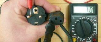
Is it possible to carry out the test using a conventional multimeter, which every radio amateur has, especially since modern versions of this device provide a special mode for checking diodes?
It turns out there is such a possibility. Although the mentioned mode, due to insufficient power supply, will not help in this case. Instead, we will use the mode for measuring transistor parameters , which is also provided in every modern digital multimeter model.
To study transistors, the tester is equipped with a special connector to which the element leads are connected. It is labeled with the letters PHP. The cathode of the ultra-bright LED (this is the shortest pin) must be connected instead of the collector (position “C” on the connector), and the anode - instead of the emitter (position “E”). If the element is valid, it will begin to glow, and the position of the measurement mode switch in this case does not matter.
In most cases, the lighting element is part of the LED circuit and it will not be possible to plug it directly into the PHP connector without unsoldering. It is not possible to check it using probes, since they cannot be connected to the connector.
The problem can be solved by making a simple design consisting of an adapter and probes connected to it from an old or broken multimeter.
How to make probes with an adapter for a PHP connector
We need very little:
- two unnecessary probes (the plugs must be cut off);
- a small fragment of double-sided textolite;
- a pair of metal clips;
- SMD LED (necessary for ease of use, but the device will work without it).
A paper clip should be soldered to the textolite plate on each side, having first bent their ends 180 degrees. The result will be something like an electric plug.
The thickness of the PCB fragment should be such that the distance between the pins of the “plug” corresponds to the distance between the inputs “C” and “E” on the PHP connector. That's all, the adapter is ready. All that remains is to solder the wires from the probes to it (again on both sides).
It is better to place the textolite between the paper clips asymmetrically. This will make it easier to understand which side the adapter should be plugged into the transistor connector of the multimeter, so as not to confuse the polarity.
The design can be supplemented with an SMD type LED, which will serve as an indicator.
How to make a dipstick with your own hands
If you don't have standard probes to sacrifice, you can use homemade ones instead. To make them you will need:
- a pair of needles;
- tinned wire with a diameter of 0.2 mm (removed from a stranded wire).
The wire should be wound around the needle so that its turns fit snugly against each other, and then soldered. It is very convenient to use nickel-plated needles for this purpose , then soldering is done as easily and quickly as possible. Often such a probe provides better contact than a standard one.
How to check led driver with a multimeter
Check all LEDs. You've already soldered something there, judging by the photo. As you know, for an LED it is the current that matters, not the voltage. So measure the current through the LEDs. And the voltage should be approximately 78 V (26 pairs of LEDs of approximately 3 V each). What are the sizes of the lights? If the size is 5.7 mm X 3 mm, then these are LEDs of the 5730 brand. Find the parameters on them and it will become clearer to you.
ctc655, yes, I checked the LEDs 5730 again, they are all intact, the current consumption of the entire assembly is only 150 mA, in this lamp two identical assemblies of LEDs and drivers died at the same time
How did you check the LEDs? What kind of rations are in the photo? We need to look at the driver circuit. Are both drivers on the same board? If on one. So we need to look at what is common there. 150 mA is the current of one LED, if you have them turned on in pairs, the current should be about 300 mA. Either there is a dead LED somewhere or you need to look at the driver. Measure the voltage drop across all LEDs.
ctc655, I checked the LEDs with a multimeter to test the diodes, also with a Chinese ESR meter, soldering is a replacement for the LED, each driver is on a separate board, the voltage drop on the LEDs is 2.45 V, if you don’t mind we can talk to you, I didn’t find the circuit diagram
It is advisable to check the LEDs with a voltage of about 3.3.3 V. I use either an regulated power supply or a lithium battery with a 50 ohm resistor. If you also control the current, then it’s generally good. To begin with, you can check in pairs. If there is a bad glow or blinking, then replace it. The driver circuit can be found relatively easily. Find the datasheet for the chip in the driver. There is a typical connection diagram. It is not recommended to turn on the driver without LEDs.
The problem with the datasheet is that the mikruh says 9911 and that’s it, but as I understand it, it’s AN9911, but maybe I’m wrong, it seems to me that it’s in the driver, well, in general, it’s a problem with the driver, how can I check the microcircuit?
Instead of LEDs, I would try to connect a regular incandescent lamp 220V-100W or 60W. By the glow of the lamp you will understand whether the driver is alive or not.
good afternoon Guys, can anyone tell me where I can find the AN9911 switching circuit, thanks in advance I found a short description, but I can’t find the circuit diagram
How the driver works
The LED driver is a constant current source that creates a voltage at the output. Ideally, it should not depend on the load applied to the driver. The AC network is characterized by instability and often experiences significant changes in parameters. The stabilizer should smooth out differences and prevent their negative impact.
For example, by connecting a 40 Ohm resistor to a 12 V voltage source, you can get a stable current reading of 300 mA.
If you connect two identical 40 Ohm resistors in parallel, the output current will be 600 mA. This circuit is quite simple and typical for the cheapest electrical appliances. It is not capable of automatically maintaining the required current strength and fully resisting voltage ripples.
Power drivers for LEDs are divided into two large groups: linear and pulsed, based on their operating principle.
Pulse stabilization
Pulse stabilization is reliable and efficient when working with diodes of almost any power.
Figure 3. Pulse stabilization circuit of the LED circuit.
The regulating element is a button, the circuit is supplemented with a storage capacitor. After applying voltage, a button is pressed, causing the capacitor to store energy. The button then opens, and DC voltage from the capacitor is supplied to the lighting equipment. As soon as the capacitor is discharged, the procedure is repeated.
An increase in voltage allows you to reduce the charging time of the capacitor. The voltage supply is triggered by a special transistor or thyristor.
Everything happens automatically at a speed of about hundreds of thousands of circuits per second. The efficiency in this case often reaches an impressive 95%. The circuit is effective even when using high-power LEDs, since energy losses during operation are negligible.
Scheme and connections of smooth ignition and attenuation of LEDs
Linear stabilizer
The linear principle of current regulation is different. The simplest diagram of such a circuit is shown in the figure below.
Figure 4. Scheme of using a linear stabilizer.
A resistor is installed in the circuit to limit the current. If the supply voltage changes, changing the resistance of the resistor will allow you to set the desired current value again. The linear regulator automatically monitors the current passing through the LED and, if necessary, regulates it using a resistor switch. The process proceeds extremely quickly and helps to quickly respond to the slightest fluctuations in the network.
Such a scheme is simple and effective, but there is a drawback - useless dissipation of the power of the current passing through the control element. For this reason, the option is optimal when used with low operating current. The use of high-power diodes may result in the control element consuming more energy than the lamp itself.
Types of LEDs that are used in 220 Volt lamps
Checking the LED Bridge
It is not possible to illuminate the entire bridge with a multimeter. Sometimes you can get a slight glow in Hfe. The diode test mode tests each chip separately.
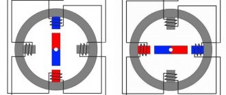
If live parts are being tested, the tester should be set to continuity mode and walked through each power terminal at all ends of the area being tested. This way you can find the damaged part of the bridge. In the photo, blue and red stripes highlight the areas that should be called from the beginning of the tape to the end.
Life time
Drivers have their own resources. Most often, manufacturers guarantee 30 thousand hours of driver operation during intensive use.
The service life will also be affected by voltage changes in the network, temperature, and humidity.
Insufficient load can significantly reduce the life of the device. If a driver is rated at 200 watts but operates at 90 watts, most of the free power is causing network congestion. Failures and flickering occur, and the lamp may burn out within a year.
Infrared
As we acquire consumer electronic devices, each of us gradually becomes the owner of a whole battery of remote controls. As long as the equipment obediently responds to your commands, there is nothing to worry about.
But it is quite possible that desperate attempts to change the channel or turn down the brightness of the chandelier do not lead to any result. In such cases, first check the status of the infrared LED, through which the remote control transmits your requirements to the main device.
Read also: St 101e operating principle
There are several ways to check the IR LED in a remote control or other device. Let's start with the simplest:
Direct the diode radiation into the lens of a digital camera. Not only a camera will do, but also a phone, laptop, video recorder, web camera, etc. IR radiation is absolutely invisible to the human eye, but electronic “eyes” register it very well. If the LED is performing its functions properly, purple flashes will be observed on the matrix.
If you don’t have a gadget that can remove it, the suspected LED can be dismantled by replacing it with a super-bright or SMD-type LED. Just make sure that the operating voltage of both elements is the same.
If the test LED emits visible light when pressing buttons on the remote control (most likely, it will be dim), then the IR LED has already served its purpose.
A more complicated method, but it does not require a camera or soldering. You can use an infrared photodiode. When infrared radiation hits the sensor of this element, a potential difference is formed at its terminals.
To test any IR LED, its radiation must be directed to the sensitive area of a photodiode previously connected to the open input of the oscilloscope.
If pulse curves appear on the device screen, the LED under test is in working condition. If you observe complete calm, then it’s time to buy a new IR LED.
How to check led driver with a multimeter
interesting homemade radio circuits
Hello. High-PF-3000mA-100W-DC-30V-36V-Dimmable-Isolated-Constat-Current-LED-Driver-for-100w-led LED driver arrived yesterday. How to check its functionality (a 100-watt matrix will not come soon). What to load?
why check it, you can load it with light bulbs, turn on 3 of them in series at 12V
It has 3 amps 30 volts. This means you need a load resistance of 10 Ohms 100 watts. Or make up resistors, or pick up something similar (car bulbs, etc.)
When it starts to warm up, it means current is flowing.
When I tried to test the China driver 18V/0.65A (for $2) with a 33 Ohm resistor, I got the following problems: PWM and a diode bridge, together with a fuse. Is it worth subjecting a 17.5 driver to such a check? It’s better to let it crash when tested with a resistor than connected to expensive diodes. The driver is faulty and cannot start normally. Perhaps it doesn’t handle 100W, try turning it on to a 220V 60W lamp. Yes, and it’s difficult to check on lamps; the resistance of a cold filament is much lower. He assured me that my ice element in the flashlight was faulty. Is Ice actually working? Otherwise it really looks like it is closed and the driver goes into defense. What wattage lamps did you connect? One was connected to 36 volts 60 watts. She blinks. Then I connected three twelve-volt automobile ones in series. it turned out 36 volts 63 watts. these also blink. then the Chinese asked to connect three lamps in parallel. I took 24 volt lamps and connected them in parallel. They also blink. Here's a hat. The seller claimed that only a 100-watt ice lamp can be connected to the driver and nothing more.
Added (10/18/2017, 21:29) ——————————————— Yes, I also checked it without load. The output showed 55 volts, with fluctuations of about 2 volts
Added (10/19/2017, 08:45) ——————————————— Damn, I think I found my jamb. Today I decided to connect my ice chip through a 35 volt transformer via a diode bridge. And look through the welding mask to see if all the elements are burning. It turned out that only two rows of LEDs were lit. Damn, without a mask everyone seems to burn very brightly. And I attacked the Chinese in vain. Sadness
How to check without soldering the diode
LEDs installed on the board are checked using a probe. But standard tools may not fit into the transistor connector. Here you will need a thin conductor. It can be:
- sewing needles;
- part of a cable or strand of stranded wire;
- straightened paper clips.
The conductor will have to be soldered to the foil probe or connected without a plug, getting an adapter. If you use a foil plate with soldered pieces of wire, you need to insert it into the appropriate slot of the multimeter and use homemade probes.
Diagnostics of the LED in the flashlight
An LED flashlight, battery-powered or other types, is a fairly reliable device, but it is not immune to breakdowns. If, even after installing new batteries, the glow remains weak or completely absent, you need to check the functionality of the LEDs and their drivers.
Before diagnosing a flashlight, it would be a good idea to check the batteries (even if they have just been unpacked) on some known good device. This advice may seem trivial to some, but quite often, as practice has shown, the cause of “showdowns” with household electronics is defective batteries, which is the last thing the home craftsman realizes.
Checking the flashlight is carried out in the following sequence:
- Unscrew the cap or conical part at the front of the housing.
- We remove the LED module.
- There are two contact pads on the LED board, to which the red and black wires are connected. The red wire corresponds to the positive polarity (marked “+” on the board), and the black wire corresponds to the negative polarity (marked “-”). In accordance with the polarity, a voltage of 3–4 V (no more than 4.2 V!) should be briefly applied to the contacts. If the brightness of the LED has not changed, then it needs to be replaced. Otherwise (the LED lights up properly), the driver must be replaced.
- Replacing an LED is only possible if its board is attached to the LED module capsule with screws. If the board is mounted on hot-melt adhesive, replacement will be impractical; in this case, the entire module is replaced.
After unscrewing the board, unsolder the LED and then install a new one.
In flashlights, LEDs are installed on aluminum radiators. To ensure effective heat dissipation, a fresh coat of special heat-conducting paste, also called thermal paste, should be applied to the heatsink before installing a new LED. The old dried layer, even if quite thick, cannot be reused and must be removed.
The test of a separate LED and the simplicity of the tester’s design are clearly demonstrated in the following video from the largest supplier of electrical equipment in Russia.
Often, when one or another electronic device breaks down, we without hesitation take the victim to repair, where we are presented with a hefty bill. Meanwhile, the cause of the accident may simply be a failure of the LED, which can easily be replaced on your own.
Thus, the ability to check the performance of these elements, which are used quite widely today, will save money and reduce repair time to a minimum.
LED lamps are popular and have many advantages, but their complex design means that the location of the breakdown is not always obvious. Checking the LEDs for functionality, if they break down, allows you to determine the cause of the malfunction and decide the fate of the problematic device. Let's look at how you can find out the condition of lamps at home using a standard tester.
220V LED lamp driver circuit
The current stabilizer in the case of an LED lamp is installed in the base of the device. And it is based on inexpensive microcircuits, for example, CPC9909. Such lamps must be equipped with a cooling system. They last much longer than any other, but it is better to give preference to trusted manufacturers, since the Chinese ones have noticeable hand soldering, asymmetry, lack of thermal paste and other shortcomings that reduce service life.
Driver circuit for LED lamp
Continuity of individual LEDs
This type of test is one of the simplest and is done using a multimeter. A standard LED has two long contacts - an anode and a cathode. The cathode leg is slightly longer, and when viewed against the light, its electrode inside the housing is larger. In order to ring the LED, you must perform the following steps:
- move the switch to the Hfe position (this is the transistor test mode);
- find the connector on the panel marked PNP and NPN;
- The anode is inserted into slot C of the PNP zone, and the cathode is inserted into slot E of the NPN zone.
These pins are the positive and negative electrodes and cause the LED to glow. If this does not happen, then either the polarity is reversed (the diode leads must be swapped), or the element is faulty. Before checking an LED with a multimeter, it is recommended to determine where its anode and cathode are.
Since multimeters have different designs and characteristics, there are several types of sockets for testing transistors.
Read also: How to fix headphones if one comes off
Despite the differences, they all have the required slots.
How to find the cause of the breakdown
When you turn on the light and the lamp does not light up, unscrew it from the socket and replace it with another one.
If light appears, then the fault lies in the lamp itself. If there is no light when using a known working light bulb, this indicates that there is a problem with the wiring. Use a multimeter to determine the cause of the problem. With its help, you can check the presence of voltage, starting from the switch. Then check the base and antennae of the cartridge. If, as a result of checking the described elements, no problems were identified, then it is clear that the problem is in the lamp itself. In order to determine the reason why the lamp does not work, it needs to be disassembled. First of all, pay attention to the driver details. To check the functionality of the part, it must be removed from the board. Resistor values will be indicated on the board itself, and the capacitor values will be indicated on the case. Ingredients should not be darkened, swollen or burnt
Inspect the soldering area, it should be of high quality without any cracks or holes in the soldering area. A failed capacitor can be identified visually; it is swollen or burst. If the driver is in order, then we inspect the board where the LEDs are located. Typically, burnt-out LEDs are immediately noticeable; they either burn out or burn out completely. In the system, diodes are connected in series, and if one fails, then all the others stop working. If problems are found, they must be corrected. The burnt part is replaced with a similar one, and if the soldering makes you suspicious, then you need to resolder these places using a large amount of flux.
If, upon visual inspection, everything looks normal, then we will carry out further repairs using a tester. The LEDs are checked first, since this unit fails in most cases. Turn the multimeter into diode test mode, and ring each LED in two directions. In one direction the device may show resistance, while in another it may glow. If a part is faulty, it is replaced.
Checking the infrared diode
There is an IR diode in every remote control (television or other device). The procedure is exactly the same as in the case of testing a conventional LED with a multimeter. But checking an infrared diode is more difficult, since it is impossible to see its glow with the naked eye. When you press a button on the remote control, nothing happens externally.
Similar diodes are used to illuminate surveillance cameras in night mode. You can use your phone's camera, which sees the glow and will help resolve the issue with visual control. If you need to check the general condition and determine the source of the problem, you can simply solder a regular LED in parallel. If it starts to blink, then the IR diode is to blame, and if this does not happen, the cause of the malfunction is in the remote control itself.
Checking the diode on the board
It is often necessary to test an LED without desoldering it from the circuit. In such cases, the technique remains the same, but the technology changes. Since it is impossible to insert the LED legs into the multimeter slots, probes are used. The hole sizes of the slots for testing transistors are too small, so the probes will have to be modified. Thin contacts should be attached to the free ends, which can be used as:
- sewing needles;
- straightened paper clips;
- pieces of thin wire, etc.
Some craftsmen use a small plate of getinax or textolite foil on both sides, to which pieces of wire are soldered, forming something like a fork. It is inserted into the required slots of the multimeter, after which you can use standard (not modified) probes.
Attention! Testing LEDs in a flashlight is done in a similar way, but the design of the device most often does not allow access to the board. You have to carefully solder it from the battery pack, remove it from the case, after which you can check the elements using multimeter probes in the usual way.
Types of drivers
All drivers are distinguished according to three criteria - the method of stabilization, design features and the presence/absence of protection. Let's consider all the options in more detail.
Linear and pulse
Depending on the current stabilization circuit, drivers are divided into two types - linear and pulsed. They differ in operating principle and efficiency.
The electronic driver circuit is tasked with ensuring stable values of current and voltage supplied to the crystal (LED). The simplest and cheapest option is to include a limiting resistor in the circuit.
Linear power circuit:
This elementary circuit is not capable of automatically maintaining current. As the voltage increases, it increases proportionally and, when it exceeds the permissible value, the crystal will collapse from overheating.
More complex control is carried out by connecting a transistor to the circuit. The disadvantage of a linear circuit is that the power decreases as the voltage increases. This option is acceptable when operating low-power LED sources, but when operating high-power LEDs, such circuits are not used.
Advantages of a linear circuit:
- simplicity;
- cheapness;
- relative reliability.
Along with linear circuits, current and voltage can be stabilized by pulse stabilization:
- after pressing the button, the capacitor is charged;
- after being released, the capacitor discharges, releasing the stored energy to the semiconductor element (LED), which begins to emit light;
- if the voltage increases, the charging time of the capacitor decreases; if it decreases, it increases.
The user does not have to press a button - the electronics do everything for him. The role of the push-button mechanism in modern power supplies is performed by semiconductors - thyristors or transistors.
The considered operating principle is called pulse width modulation in electronics. Tens and even thousands of operations can occur per second. The efficiency of such a scheme reaches 95%.
Simplified pulse stabilization scheme:
Electronic, dimmable and capacitor-based
The scope of its application and performance characteristics depend on the principle of the driver design.
Types of drivers by device principle:
- Electronic. Their circuits necessarily use a transistor. A capacitor is installed at the output, eliminating or at least smoothing out current ripples. Electronic converters are capable of stabilizing currents up to 750 mA. Electronic drivers fight not only ripples, but also electromagnetic high-frequency interference induced by electrical appliances (radio, TV, router, etc.). The presence of a special ceramic capacitor allows you to minimize interference. The downside of the electronic driver is its high cost, but the plus is that the efficiency is close to 95%. They are used in powerful LED lamps: car headlights, floodlights, street lamps.
- Dimmable. A special feature of dimmable drivers is the ability to control the brightness of the lamp. The adjustment is based on a change in the output current, which determines the brightness of the light flux. The driver can be included in the circuit in two ways: between the lamp and the stabilizer or between the power source and the converter.
- Based on capacitors. These are inexpensive models used for budget LED lamps. If the manufacturer did not provide a smoothing capacitor in the circuit, then ripple is observed at the output. Another disadvantage is insufficient security. The advantage of such models is their high efficiency, tending to 100%, and the simplicity of the circuit. Such drivers are easy to assemble with your own hands.
Capacitor drivers may cause flicker and are not recommended for use with indoor applications. Flickering has a harmful effect on vision and irritates the nervous system.
With or without housing
The driver may or may not be located inside a protective housing. Electronic circuits are vulnerable to many external factors, so placing the driver in a housing is considered a more reliable option.
The housing protects the electronic converter from moisture, dust, direct sunlight, etc. Unframed models are cheaper, but they have a shorter service life and worse operating stability. They are more suitable for hidden installation.
How to ring an LED lamp
Let's look at how to check an LED light bulb with an E27 base, suitable for ordinary household lamps and chandeliers. Before you test an LED lamp with a multimeter, you will have to disassemble it. First you need to disconnect the diffuser. It is usually glued to the body, so you need to carefully insert a piece of thin plastic (plastic card, pick or other object) into the slot and, gradually moving it along the gluing line, separate the parts. If the seam is too strong and does not give in, you can warm it up with a hairdryer. Testing the open board with a multimeter is done using probes.
Alternatively, you can use a Krona battery. You need to select the desired polarity and check the status of the LEDs with short touches. You cannot maintain contact for a long time because the battery voltage is too high.
How to check the driver if there is no matrix?
Re: How to check the driver if there is no matrix?
ivdor » Dec 20, 2016 03:25 AM
It is neither something as nor any what. And as far as it’s concerned, it’s unconditional. It would not be necessary, but if such a thing were to happen, here I am for you. I'm done.
PS: Use the above information at your own risk.
Re: How to check the driver if there is no matrix?
Invisible_Light » Dec 20, 2016, 03:45
Re: How to check the driver if there is no matrix?
ivdor » December 20, 2016, 03:51
It is neither something as nor any what. And as far as it’s concerned, it’s unconditional. It would not be necessary, but if such a thing were to happen, here I am for you. I'm done.
PS: Use the above information at your own risk.
Re: How to check the driver if there is no matrix?
by divian » Dec 20, 2016 04:54 AM
Re: How to check the driver if there is no matrix?
Invisible_Light » 20 Dec 2016, 09:14
Re: How to check the driver if there is no matrix?
DC » Dec 20, 2016 3:24 pm
Re: How to check the driver if there is no matrix?
by divian » Dec 20, 2016 3:31 pm
Re: How to check the driver if there is no matrix?
DC » Dec 20, 2016 3:49 pm
Re: How to check the driver if there is no matrix?
by divian » Dec 20, 2016 3:58 pm
Re: How to check the driver if there is no matrix?
DC » 20 Dec 2016, 15:59
Re: How to check the driver if there is no matrix?
VASYA » Dec 29, 2016, 06:03
Re: How to check the driver if there is no matrix?
Squirrel » Jan 27, 2022 2:28 pm
Re: How to check the driver if there is no matrix?
Pilot » 04 Mar 2022, 04:18
Re: How to check the driver if there is no matrix?
Invisible_Light » 04 Mar 2022, 13:28
Re: How to check the driver if there is no matrix?
Pilot » 05 Mar 2022, 01:05
LED sources must be connected to the power supply through special devices that stabilize the current - drivers for LEDs. These are 220 V AC voltage converters to DC voltage with the parameters necessary for the operation of light diodes. Only with their presence can one guarantee stable operation, long service life of LED sources, declared brightness, protection against short circuits and overheating. The choice of drivers is small, so it is better to first purchase a converter and then select LED lighting sources for it. You can assemble the device yourself using a simple diagram. Read about what an LED driver is, which one to buy and how to use it correctly in our review.
Powerful LED with stabilizer
Checking the LED spotlight
First you need to determine what type of LED is installed in the spotlight. There may be two options:
- board with small SMDs;
- one large yellow element.
The LED is checked for serviceability based on its type. For a board with SMD, the already discussed method of testing with a multimeter is used. This method is not suitable for large yellow samples, since their supply voltage ranges from 10 to 30 V, which is too high for a multimeter. There is only one way to check such a device yourself - using a known working, serviceable driver that matches the operating parameters of the LED being tested.
How to make a driver for LEDs with your own hands
The device can be made from any unnecessary phone charger. It is necessary to make only minimal improvements and the microcircuit can be connected to LEDs. It is enough to power 3 1 W elements. To connect a more powerful source, you can use boards from fluorescent lamps.
Important! During work it is necessary to observe safety precautions. Touching exposed parts may result in an electric shock of up to 400 V.
| Photo | Stage of assembling the driver from the charger |
| Remove the housing from the charger. | |
| Using a soldering iron, remove the resistor that limits the voltage supplied to the phone. | |
| Install a tuning resistor in its place until it needs to be set to 5 kOhm. | |
| Using a serial connection, solder the LEDs to the output channel of the device. | |
| Remove the input channels with a soldering iron, and in their place solder a power cord to connect to a 220 V network. | |
| Check the operation of the circuit, set the regulator on the trimming resistor to the required voltage so that the LEDs shine brightly but do not change color. |
Example of a driver circuit for LEDs from a 220 V network
How to check LED strip for performance
It is difficult to check the entire LED strip using a multimeter at once. It will not be possible to make it glow; only sometimes a faint glow occurs when checking in Hfe mode. You can check all the LEDs one by one.
Most often, contact tracks fail, which are checked along the entire length of the tape. It is conventionally divided into equal sections consisting of 3 LEDs. The border of each is marked on the tape with a transverse line with contacts. Touching them, check each segment, identifying the damaged area. In addition, it is necessary to check the power supply of the tape with a multimeter, since it is also subject to stress and periodically fails.
Where to buy drivers for LEDs
The cost of the driver can reach 300 rubles and more
Selling companies offer a huge range of drivers for LEDs, the technical characteristics and prices of which can be seen in the price lists. As a rule, product prices are indicative and are specified when ordering from the project manager. The range includes converters of various powers and degrees of protection, used for external and internal lighting, as well as for illumination and tuning of cars.
When choosing a driver, you should take into account the conditions of its use and the power consumption of the LED design. Therefore, it is necessary to purchase a driver before purchasing LEDs
So, before you buy a driver for 12 volt LEDs, you need to take into account that it should have a power reserve of about 25-30%. This is necessary in order to reduce the risk of damage or complete failure of the device due to a short circuit or voltage surges in the network
The cost of the converter depends on the number of devices purchased, form of payment and delivery time.
The table shows the main parameters and dimensions of 12 volt voltage stabilizers for LEDs, indicating their estimated price:
| Modification LD DC/AC 12 V | Dimensions, mm (h/w/d) | Output current, A | Power, W | price, rub. |
| 1x1W 3-4VDC 0.3A MR11 | 8/25/12 | 0,3 | 1x1 | 73 |
| 3x1W 9-12VDC 0.3A MR11 | 8/25/12 | 0,3 | 3x1 | 114 |
| 3x1W 9-12VDC 0.3A MR16 | 12/28/18 | 0,3 | 3x1 | 35 |
| 5-7x1W 15-24VDC 0.3A | 12/14/14 | 0,3 | 5-7x1 | 80 |
| 10W 21-40V 0.3A AR111 | 21/30 | 0,3 | 10 | 338 |
| 12W 21-40V 0.3A AR11 | 18/30/22 | 0,3 | 12 | 321 |
| 3x2W 9-12VDC 0.4A MR16 | 12/28/18 | 0,4 | 3x2 | 18 |
| 3x2W 9-12VDC 0.45A | 12/14/14 | 0,45 | 3x2 | 54 |
Other verification methods
In addition to a multimeter, you can check LEDs using a battery. The best option is a CR2032 battery, which is used in the computer motherboard. Its voltage is 3 V, which is enough for most LEDs.
It is possible to use 4.5 or 9V batteries, but in such cases you will need to connect a ballast resistor, which gives a voltage drop to safe levels. For Krona you will need 750 Ohms, for 4.5V batteries - 150-200 Ohms.
The LED strip can be checked with a 12 V battery. These are found in remote controls and doorbells. By connecting the contacts of the tape to the corresponding poles of the battery, areas with burnt-out elements are determined. No less problematic elements are the connection areas of individual parts of the LED strip - connectors that oxidize and stop conducting current. Before you start dialing, you need to check their condition - perhaps the problem lies there.
Important! If you need to test a UV LED, you should be careful when connecting it to a power source. Such devices are sensitive to overvoltage and easily fail. The nominal value for which the ultraviolet LED is designed is 3.4-4 V, these figures cannot be exceeded.
How to calculate
For the correct organization of the electrical circuit, it is important to calculate the output parameters. Based on the data obtained, a specific model is selected.
Thematic video: How to choose a driver for an LED lamp.
The calculation begins by considering the LEDs, taking into account their voltage and current. The characteristics can be seen in the documents. For example, diodes with a voltage of 3.3 V and a current of 300 mA are used. It is necessary to create a lamp in which three LEDs are located one after the other in series. The voltage drop in the circuit is calculated: 3.3 * 3 = 9.9 V. The current in this case remains constant. This means that the user will need a driver with an output voltage of 9.9 V and a current of 300 mA.
It will not be possible to find such a specific unit, since modern devices are designed for use in a certain range. The device current may be slightly less, the lamp will be less bright. Exceeding the current is prohibited, since this approach can damage the device.
Now you need to determine the power of the device. It’s good if it exceeds the required figure by 10-20%. The power is calculated using the formula, multiplying the operating voltage by the current: 9.9 * 0.3 = 2.97 W.
Figure 7. Driver board.
Main conclusions
It is not difficult to check LEDs with a multimeter if you understand the principle of their operation. The main task is to prepare the conditions, modify the probes or make special contacts. The correct polarity plays an important role, changing which will not allow even a working element to glow. The process does not take much time; preparation, dismantling or disassembling of devices takes longer. The general principle is to apply the appropriate voltage to the problem element, from which it should light up if it is in working condition. If the glow is not observed even when the polarity is changed, it means that the LED (or section of the strip) is faulty and must be replaced.
Read also: Oblique chisels for wood
Testing an LED with a multimeter is the easiest and most correct way to determine its performance. A digital multimeter (tester) is a multifunctional measuring instrument, the capabilities of which are reflected in the switch positions on the front panel. LEDs are checked for functionality using functions present in any tester. Let's look at the testing methods using the DT9208A digital multimeter as an example. But first, let’s touch a little on the topic of the reasons for the malfunction of new light-emitting diodes and the failure of old ones.
Main characteristics of drivers
Key parameters of current conversion devices that you need to rely on when choosing:
- Rated power of the device. It is indicated in the range. The maximum value must be slightly greater than the power consumption of the connected lighting fixture.
- Output voltage. The value must be greater than or equal to the total voltage drop across each circuit element.
- Rated current. Must match the power of the device to provide sufficient brightness.
Depending on these characteristics, it is determined which LED sources can be connected using a specific driver.
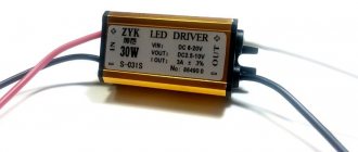
All important information is on the device body
The main causes of malfunction and failure of LEDs
A feature of any emitting diode is its low reverse voltage limit, which is only a few volts higher than the drop across it in the open state. Any electrostatic discharge or incorrect connection during circuit adjustment can cause the LED (abbreviation for Light-emitting diode) to fail. Ultra-bright, low-current LEDs, used as power indicators for various devices, often burn out as a result of power surges. Their planar counterparts (SMD LEDs) are widely used in 12V and 220V lamps, strips and flashlights. You can also verify their serviceability using a tester.
It is worth noting that a small proportion of defective LEDs (about 2%) are supplied from the manufacturer. Therefore, additional checking of the LED with a tester before mounting it on a printed circuit board will not hurt.
What are LED drivers and why are they needed?
LEDs are semiconductor elements. The brightness of their glow is determined by current, not voltage. For them to work, they need a stable current of a certain value. At a pn junction, the voltage drops by the same number of volts for each element. Ensuring optimal operation of LED sources taking into account these parameters is the driver’s task.
Exactly what power is needed and how much the voltage drops during the pn junction should be indicated in the passport data of the LED device. The converter parameter range must fit within these values.
Essentially, the driver is a power supply. But the main output parameter of this device is stabilized current. They are produced according to the principle of PWM conversion using special microcircuits or based on transistors. The latter are called simple.
The converter is powered from a regular network and outputs a voltage of a given range, which is indicated in the form of two numbers: the minimum and maximum values. Usually from 3 V to several tens. For example, using a converter with an output voltage of 9÷21 V and a power of 780 mA, you can ensure the operation of 3÷6 LED elements, each of which creates a drop of 3 V in the network.