Operating principle
The operating principle is based on tracking circuit pulses. Current is supplied to the probe and applied to the contact. The indicator part monitors the voltage level and sends a signal to the control board. The models use an insulating part to ensure safety during operation.
Pointer Operation
The probe or tip can be connected to a flexible wire or tube. When the voltage exceeds the permissible limits, the indicator may not respond. There are models with and without a screen. Simple options are used with LED lamps.
Application area
The equipment is in demand at enterprises that use high voltage installations. Most often this is necessary at substations. Thus, there is a need to carry out phasing taking into account the voltage class. It is also possible to test cables and individual power lines.
Power lines
Interesting! It is allowed to check DC and AC transformers.
Technical description and purpose
The high voltage indicator “IVA-02” is designed for visual and remote monitoring of the presence or absence of high voltage on the main electrical circuits in alternating current electrical installations with voltage from 6 to 35 kV, frequency 50/60 Hz.
The indicator has a built-in relay with a configurable function for signaling and control and allows the use of electronic blocking of the disconnector in the presence of voltage on the switchgear busbars.
High voltage sensors have two versions.
Remote high-voltage sensors are installed opposite the current-carrying parts of the switchgear when the installation of sub-insulator sensors or capacitive dividers is structurally impossible; this design is the same for the voltage class from 6 to 35 kV.
Under-insulator high voltage sensors are installed directly under the support insulators of the switchgear. Taking into account the various design features of the support insulators, a corresponding voltage sensor is installed for each voltage class.
For the first time, the indicator uses a built-in auto-calibration to adapt to the design of the switchgear, reduce various types of interference and stable operation in asymmetrical modes (phase imbalances).
To organize communication with higher-level systems, the device has a built-in RS-485 interface with support for the Modbus RTU protocol.
High voltage indicator device
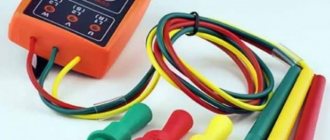
The main elements of the index are:
- tip or probe,
- insulation,
- restrictor ring,
- handle,
- thread,
- indicator part.
In some cases, a display and contact stabilizers are used. The probe can be installed on a wire or holder. Indication can be visual or audio.
Display system
Rules of application
Before using the device, it is recommended to check the contents. Using the example of UVNU - 10SZ IP, the tube, insulation, and handle are inspected. The nodes must be securely connected; screw fastenings are used. A holder is fixed to the phasing tube. The ring stop must be attached to the body.
You might be interested in this M416 grounding meter
Important! External inspection is necessary in order to identify cracks or peeling.
Pointer Defects
Any defects in the pointer indicate that it is not ready for use. If drops of water or dirt are found on the ring or tube, they must be removed. For this purpose, it is better to use a napkin. The device should be stored in a dry place, preferably protected from ultraviolet exposure.
Particular attention is paid to the hook-shaped probe. It must be examined without gloves and touched. The indicator that the device is on should light intermittently. If you hear sound, it means the device is working properly. In this way, the skin resistance is assessed and the test is completed.
If the pointer does not respond to human touch, you can try moistening your fingers a little. At sub-zero temperatures, devices operate with a large error. It is especially problematic to carry out work at temperatures of −20 degrees or more. It is recommended to select a guaranteed voltage source for the test. The presented indicator records readings from 100 to 1000 volts.
Voltage source
Important! You must hold the handle during the test.
When the probe is brought in, it must come into contact with the core. Under normal conditions, a person will hear an intermittent beep. The light will blink. This confirms that the object is energized. The contact method is necessary to determine the phase.
When using signs, the electrician often has to stand on supports. It's good to have an insulating rod. When working with high-voltage equipment, it is better to use workpieces at least 6 m long. The head is necessary for grounding. Touching live parts is sometimes accompanied by a bright light and a powerful sound signal.
Live parts
Before checking the grounding in the installation, measure the voltage. The permissible level of energy flow is 1.5 kV. If the indication does not respond, you must touch the indicator with your non-gloved hand. When the cable is under induced voltage, the indication operates in constant mode. Sometimes it is necessary to determine the phase, then a working tube is used. It connects to the pointer, as well as the pin.
To make the connection, the shunt is inserted into the hole. There are marks on the indicator; you should not make significant physical efforts. A separate issue concerns operational activities related to testing. The rules are specified in the electrical installation instructions.
You may be interested in Wire crimping tool
Electrical installations
Test objectives:
- determining the minimum level of indicator activation,
- longitudinal insulation test,
- maximum threshold test
For testing, the pointer is suspended indoors on a hill. The contact probe should be at the bottom. First of all, a slight voltage is applied to the hook; it is important to monitor the light bulb. The maximum limit of the presented modification is 1.5 kW. The longitudinal insulation test allows you to determine the permissible voltage level.
Longitudinal insulation test
Important! The device in good condition can withstand a load of 12 kV.
In this case, the voltage supply time is important. The phasing tube is checked in a similar way. For this purpose, a conductive part with a voltage of 12 kV is supplied. However, when the phase is turned on oppositely, the parameter is different. It all depends on the resistance of the conductor.
An indication with a tube attached to the pointer is triggered at a load of 1.5 kV. Using the example of UVNsTF 10I, it can be seen that simple options with a phasing tube are easier to use. The model is suitable for testing cable and overhead lines. When testing electrical installations, it is important to check the serviceability of transformers.
Transformers test
The permissible operating voltage must be in the range of 6-10 kV. The indicator phasing tube can only be used in an alternating current circuit. The permissible frequency is from 50 megahertz. As the manufacturer indicates, the maximum load level is 15 kV. When using the model, contact tips and electrical circuit elements are connected.
Interesting! The indicator has two connecting wires, as well as insulation.
The rod is installed between the bushings, fastening occurs due to a threaded connection. The presented model has a three-digit display and uses LED bulbs. When voltage is applied to the hook, they light up. It also triggers if testing is performed.
The indicator is capable of functioning in self-monitoring mode. In this case, the circuit checks the health of the nodes and reports possible errors. When the device is switched to operating mode, it becomes possible to automatically determine the type of voltage. Contact with the current-carrying conductor is ensured by the tip. Determining polarity does not take much time.
Interesting! The “-” LED is activated when a negative voltage is detected in the current-carrying part. A decrease in frequency is accompanied by flickering of the light bulb.
Flickering on the indicator
Specifications
| Parameter | Meaning |
| Number of voltage control channels | 3 |
| Supply voltage DC/AC (on request), V | 85—264 (24) |
| Rated power consumption DC/AC, W | 1/1 |
| Communication channel type interface/protocol | RS-485/Modbus RTU |
| Number of output relay channels | 1 |
| Rated operating voltage of relay contacts of DC/AC output channels, V | 220 |
| Rated operating current of relay output contacts, A | 3 |
| Operating temperature range, ºС | -40…+60 |
| Relative humidity, % | 30—80 |
Security measures
Basic Rules:
- use of electric gloves,
- contact is made to the working part,
- rod insulation,
- Do not use in the rain,
- compliance with GOST 20493-2001 standards.
You may be interested in this. Features of the multimeter
Voltage indicators above 1000 V are discussed above. The differences lie in the design and technical characteristics. For devices, the rules of use and precautions are specified in the instructions.
UVNsTF-6-10 voltage indicator 6…10 kV with phasing
Purpose of the indicator UVNsTF-6-10
The UVNsTF-6-10 high-voltage phasing indicator is designed for phasing cables, overhead lines and transformers in electrical installations with a voltage of 6-10 kV AC industrial frequency.
Specifications
- The rated voltage of the electrical installation is 6 -10 kV.
- Voltage indication occurs at the following values:
| Rated voltage of the electrical installation, kV | Voltage indication, kV | |
| According to the consonant inclusion scheme, no less | According to the counter-connection scheme, no more | |
| 6-10 kV | 12,7 | 1,5 |
- Dimensions of the device in working condition: 44 x 780 mm.
- The insulating part is at least 270 mm long.
- Handle – length at least 110 mm.
- Connecting wire - length at least 1000 mm.
- Test voltage of the insulating part is 40 kV for 5 minutes.
- Test voltage of the connecting wire is 20 kV for 1 minute.
- Indication of power supply discharge when the voltage drops to 2.4 V
- Weight of UVNsTF-6-10 without packaging - less than 700 g
Terms of Use:
- ambient temperature -30°С…+40°С (lower limit depends on the type of power supply elements);
- — relative air humidity no more than 98% at a temperature of 25°C;
- — atmospheric pressure 61-105 kPa (461-799 mm Hg)
Contents of delivery
- Working parts with connecting wire – 1 pc.
- Insulating rod with handle – 2 pcs.
- Operating manual – 1 piece
- Case – 1 pc.
Design and principle of operation of the UVNsTF-6-10 indicator
The UVNsTF 6-10 high voltage indicator is a two-pole device with light and sound indication, operating in direct contact with live parts of electrical installations that are energized.
The pointer and phasing tube consist of two parts, the connection of which is carried out using threaded couplings. All parts are made of electrical insulating material. One part is working, the other is insulating with a handle. The working parts are connected to each other by wire. LEDs are installed in the working parts, providing visual control during phasing. Sound indication is provided by a built-in sound indicator/buzzer.
UVNsTF-6-10 provides control and indication of the discharge of the built-in battery.
Preparation for work and work procedure
- Transport the pointer to the work site in a protective case, protecting it from shock and mechanical damage.
- At the work site, bring the indicator into working condition by connecting the working and insulating parts using threaded bushings.
- Carry out an external inspection of the indicator. If damage is detected or there are no marks on operational tests, the use of the UVNsTF-6-10 indicator is prohibited!
- When working with the device, the use of dielectric gloves is mandatory.
- Check the serviceability of the product before using it in the workplace by connecting it bipolarly to the phase and to a grounded structure. In this case, there must be clear light and sound signals. If the voltage phases on the controlled current-carrying parts coincide, the indicator does not produce signals. Flashing of the lower LED indicates the need to replace the batteries.
- Phasing work should be carried out in accordance with the 'Rules for the technical operation of electrical installations' and local instructions.
Maintenance
- Maintenance, accounting and storage of the product is carried out in accordance with the current “Instructions for the use and testing of protective equipment used in electrical installations”.
- Checking the serviceability of the pointer is carried out by touching the tip contacts to live parts that are known to be energized. The blinking of the lower LED indicates the need to replace the batteries.
Replacing batteries for voltage indicator UVNsTF-6-10
The batteries are located in the working part of the pointer. To replace them you need:
- unscrew the body of the working part from the connecting sleeve;
- pull out the board with batteries;
- Replace batteries, observing polarity.
Reassembling the parts of the high voltage indicator after replacing the batteries is done in the reverse order. The batteries recommended for installation are alkaline, with a capacity of at least 1 Ah.
Checking the technical condition of UVNsTF 6-10
Mechanical tests of the product during operation are not carried out.
Electrical tests of the pointer during operation should be carried out in accordance with the “Instructions for the use and testing of protective equipment used in electrical installations”. Test frequency is once every 12 months. UVNsTF-6-10 is subjected to the following types of tests and control:
- Checking the electrical strength of insulating parts. It is carried out for each of the insulating parts with a test voltage of 40 kV in the following sequence: Connect the electrodes of the test installation (UT) to the threaded bushing and a temporary electrode placed at the restrictive ring on the side of the insulating part.
- Enable DUT. Raise the voltage to 13 kV. In accordance with GOST 1516.2, the rate of voltage rise to 1/3 of the test voltage can be arbitrary. A further increase in voltage to 40 kV should be smooth and fast, but allowing the reading of the measuring device to be taken at a voltage of more than 30 kV.
- Maintain the insulating part under a voltage of 40 kV for 5 minutes.
- Quickly reduce the voltage to zero, or to any value not exceeding 13 kV.
- Turn off the IU, remove the electrodes.
- The insulating part is considered to have passed the test if there is no breakdown, surface overlap or local heating from dielectric losses.
- Immerse the connecting wire in a bath of water so that the distance between the wire termination point and the water level is within 60-70 mm.
- Connect the electrodes of the DUT to the contact tip and the threaded bushing.
- When determining the indication voltage using a consonant switching circuit, connect both tip contacts to the high-voltage terminal of the test setup. Do not connect the grounded terminal of the DUT to the pointer. The connecting wire of the pointer should not touch grounded objects.
- Enable DUT. Slowly and smoothly raising the voltage, record the readings of the measuring device at the beginning of a distinct glow of both indicators. If the lower LED is blinking, you need to turn off the DUT, replace the batteries and repeat the determination of the indication voltage.
- Turn off the DUT, disconnect the contact tips.
- When determining the indication voltage according to the counter-connection circuit, connect one of the tip contacts to the high-voltage terminal of the DUT, the other to its grounded terminal.
- Enable DUT. Slowly and smoothly, raising the voltage, record the readings of the measuring device at the beginning of a distinct glow of both LEDs.
- Turn off the DUT, disconnect the contact tips.
- The indicator is considered to have passed the test if the indication voltage according to the consonant connection circuit is not less than 12.7 kV, and according to the counter connection circuit - no more than 1500 V.
The service life of the high voltage indicator UVNsTF-6-10 is 5 years.
Possible malfunctions and ways to eliminate them
| Name malfunctions | Cause | Remedy |
| Pointer doesn't work | No contact in battery holders | Tighten or clean holders |
| Batteries are low | Replace batteries |