Looking for a simple phase sequence indicator in a three-phase electrical network? It is not necessary to buy ready-made ones, especially since they often do not work very correctly. It’s better to assemble such a device yourself, especially since the work and costs are minimal. So, when choosing an indicator circuit, the main assumption was to minimize the number of solder points and paths that have a power network phase potential. An additional factor was the PCB design, which allows the use of either a single bi-color LED or separate LEDs.
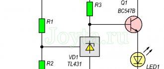
Phase sequence indicator circuit
In this circuit, each phase is current limited to improve safety. This became possible thanks to resistors at the phase inputs, which are often absent in the circuits of cheap Chinese devices. In addition, using modern elements (resistors with a minimum breakdown voltage of 500 V), the input part can be simplified.
Phase meters and phase rotation indicators
What is a phase rotation meter (indicator).
The device measures the phase angle of the signal applied to the current or voltage inputs of the measuring wire. The device determines the phase sequence in three-phase systems, both with and without a midpoint.
What is phase rotation and how to check it?
At any power supply facility, the task arises of checking phase rotation, as well as phasing. As a rule, these tasks are included in the complex of works to coordinate the parallel operation of transformers. I would like to share a short story that will touch on the topics of phase rotation in a three-phase network and correct phasing, as well as the devices and methods used in this.
After successful installation of electrical equipment and in particular transformers, commissioning work is carried out. And even with successful commissioning, when both transformers are switched on for parallel operation, a short circuit occurs. Naturally, the installers claimed that they had checked the phase rotation from both sources and everything matched.
What is phase alternation?
Everyone knows that in a three-phase network there are three different phases.
Conventionally, they are usually designated as A, B and C. Remembering the theoretical foundations, we can say that the phase sinusoids are shifted relative to each other by 120 degrees. So, there can be six different alternation orders in total, and they are all divided into two types - direct and reverse. The following order is considered direct alternation - ABC, BCA and CAB. The reverse order will be CBA, BAC and DIA, respectively. It is in order to check the order of phase alternation
that a device such as
a phase indicator
. Using this device, it is easy to measure and establish the phase sequence.
When should order be considered?
It is necessary to check the phase rotation when operating three-phase AC motors. The order of the phases will change the direction of rotation of the motor, which is sometimes very important, especially if there are many mechanisms on the site that use motors.
Types of phase rotation indicators
According to the principle of operation, electromechanical and electronic phase rotation indicators differ.
- Electromechanical phase rotation indicators
are a miniature three-phase asynchronous motor (with high slip), visual observation of the rotor of which determines the direction of field rotation (respectively, the order of phase rotation). Due to their simplicity, such indicators are highly reliable and inexpensive.
- Electronic phase rotation indicators
show
the order of phase changes is determined by performing measurements. To display the results obtained, devices of this type are equipped with LED indicators or LCD displays. Due to the fact that such models do not have moving elements, their service life is much longer than that of electromechanical devices, and measurement results are obtained faster (almost instantly after turning on the device).
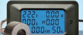
Typically, professional phase rotation indicators not only show the direction of rotation of the field, but also have the ability to measure voltage in phases (that is, they act as a voltage and current probe), due to which less time is spent on work (there is no need to perform separate measurements in each phase) .
In addition to such devices, there are also combined models of phase meters. They make it possible to determine not only the order of phase alternation, but also the direction of rotation of the rotors of electric motors. This functionality is especially useful if moving components and elements are difficult to access for visual inspection, for example, by protective covers.
How to choose a phase rotation indicator?
Before you buy a phase rotation indicator, you should pay attention to the range of frequencies and voltages at which it can perform measurements.
For drives and industrial electrical equipment, it is enough that the indicator can operate in the voltage range of 120-400 V with an industrial frequency (50-60 Hz).
When connecting transformer substations, setting up backup power systems, etc. (where three-phase step-up or step-down transformers are used), models with a wider voltage range (from 40 to 800 V) should be used.
When you decide to use the device in aviation, military or other professional systems operating at a frequency different from industrial, you should pay attention to the frequency range of the selected models (from 5 to 400 Hz).
Select and buy a phase rotation indicator in our company’s online store with delivery throughout the regions of Russia.
Correct phase order
The correct phase order is as follows: Since both LEDs are driven by additional outputs of the same flip-flop, only one LED can be lit. For the correct phase sequence, this will be green - a high state at the Q output of flip-flop A and, accordingly, a low state at the output of Q. For a reverse phase sequence, we have the reverse situation at flip-flops A and the red LED is on.
Let's see what the S and T phase voltage looks like if we consider the R phase as the reference voltage:
The rising edge at the input of the CLK generator of flip-flop A will be transferred to the output Q of the current state at the moment at the input D. As you can see in the diagram, this input is connected to phase S.
Useful: Do-it-yourself low-pass filter for a subwoofer
The synchronization process is generated from the phase (input) of the system T.
With the correct phase sequence (as in the figure above), a rising edge will occur when the H-state is reached at the D input of trigger A.
When the phase sequence of S and T changes, the state L of trigger A is in state L.
2.7. INSTRUCTIONS FOR USE AND TESTING OF PROTECTION MEANS USED IN ELECTRICAL INSTALLATIONS
2.7. Voltage indicators for checking phase coincidence
Purpose, principle of operation and design
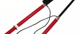
2.7.1. The indicators are designed to check the coincidence of voltage phases (phasing) in electrical installations from 6 to 110 kV.
2.7.2. The indicators are two-pole devices that are briefly switched on to the geometric (vector) voltage difference of the controlled phases. If the phases of these voltages do not coincide (divergence by a certain angle), the indicator gives a corresponding light (and sound) signal.
2.7.3. The indicators consist of two electrically insulating tubular housings connected by a flexible high-voltage wire.
Housings can be detachable or non-detachable. The housings consist of working, insulating parts and handles. The working parts contain electrode tips, units that respond to the voltage value between the controlled points, and indication elements.
The working parts at the installation site of the electrode tips should not have threaded elements.
2.7.4. The operating principle of other designs that do not contain a flexible high-voltage wire, as well as their testing methods and rules of use are given in the operating manuals.
Performance tests
2.7.5. During operation, mechanical tests of indicators are not carried out.
2.7.6. During electrical tests of indicators, the electrical strength of the insulation of working, insulating parts and connecting wires is checked, as well as their verification according to consonant and counter-connection schemes.
2.7.7. When testing the insulation of the working part, voltage is applied between the tip electrode and the threaded connector element. If the pointer does not have a threaded connector, then an auxiliary electrode for connecting the test installation wire is installed at the boundary of the working part.
2.7.8. When testing the insulating part, voltage is applied between the element of its articulation with the working part (threaded element, connector, etc.) and a temporary electrode placed at the restrictive ring on the side of the insulating part.
2.7.9. When testing a flexible wire of indicators for voltages up to 20 kV, it is immersed in a bath of water at a temperature of (25 +/- 15) °C so that the distance between the place where the wire is terminated and the water level is within 60 - 70 mm. Voltage is applied between one of the electrode tips and the bath body.
The flexible wire of voltage indicators 35 - 110 kV is tested using a similar method separately from the indicator. In this case, the distance between the edge of the wire tip and the water level should be 160 - 180 mm. Voltage is applied between the metal ends of the wire and the bath body.
2.7.10. When checking the pointer according to the consonant connection circuit, both tip electrodes are connected to the high-voltage terminal of the test setup (Fig. 2.2a).
When checking the pointer using a counter-connection circuit, one of the electrode tips is connected to the high-voltage terminal of the test installation, and the other to its grounded terminal (Fig. 2.2b).
During testing, the voltage gradually rises from zero until clear signals appear. The normalized indication voltage values for both test schemes depending on the rated voltage of the electrical installations are given in Table. 2.6.
Table 2.6
VOLTAGE INDICATORS FOR CHECKING PHASE COINCIDENCE
┌────────────────────────┬─────────────── ───────── ───────────────┐ │ Rated voltage │ Indication voltage, kV │ │ electrical installations, kV ├──────────── ───────┬ ───────────────────┤ │ │according to the consonant scheme│according to the counter scheme│ │ │inclusion, no less│inclusion, no more│ ├──── ─── ─────────────────┼───────────────────┼─── ───────── ───────┤ │6 │ 7.6 │ 1.5 │ │10 │ 12.7 │ 2.5 │ │15 │ 20 │ 3.5 │ │20 │ 28 │ 5 │ │35 │ 40 │ 17 │ │110 │ 100 │ 50 │ └────────────────────────┴── ──────────── ─────┴───────────────────┘
2.7.11. The standards and frequency of electrical tests of indicators are given in Appendix 7.
Terms of use
2.7.12. When working with signs, the use of dielectric gloves is mandatory.
2.7.13. Before use, the serviceability of the indicator is checked at the workplace by a two-pole connection to a phase and a grounded structure. In this case, there must be clear light (and sound) signals.
2.7.14. If the voltage phases on the controlled current-carrying parts coincide, the indicator does not produce signals.
Device printed circuit boards
Printed circuit boards are designed single-sided, but in two versions. The first version has only one jumper, although the ground path (which is in the potential of one of the phases) is long and does not fully meet safety requirements. The second version of the scarf has better distributed mass, but had to pay for the need to use a second jumper.
Alternation indicator tests
The layout according to the diagram was tested on a universal board. Works without problems. The total cost of the radio components was about 200 rubles (you must admit that you cannot buy a ready-made, high-quality phase rotation indicator for this money).
When performing installation, be sure to make jumpers with well-insulated wire (such as Teflon) and consider coating the board with insulating varnish. Be sure to place everything in a plastic case. Despite the described actions, we are still dealing with high voltage three-phase networks and must be very careful! For a phase voltage of 220 V, the peak value is 320 V, and for a phase-to-phase voltage of 400 V, it is 560 V, respectively.
Performance testing of voltage indicators to check phase alignment
During operation, mechanical tests of voltage indicators to check phase coincidence are not carried out.
When electrically testing voltage indicators, to check phase coincidence, the electrical strength of the insulation, working parts and connecting wire is checked, and a check is also carried out using counter and consonant connection schemes.
When testing the insulation of the working part, voltage is applied between the tip electrode and the threaded connector element. If the pointer does not have a threaded connector, then the auxiliary electrode for connecting the test installation wire is installed at the boundary of the working part.
When testing the insulating part, voltage is applied between the element of its articulation with the working part (threaded element, connector, etc.) and a temporary electrode, which is applied at the restrictive ring on the side of the insulating part.
When testing a flexible indicator wire for voltage up to 20 kV, it is immersed in a bath of water at a temperature of (25 ± 15) ° C so that the distance between the place where the wire is terminated and the water level is within 60-70 mm. Voltage is applied between one of the electrode tips and the bath body.
The flexible wire of the 35-110 kV voltage indicator is tested using a similar method separately from the indicator. In this case, the distance between the edge of the wire tip and the water level should be within 160-180 mm. Voltage is applied between the metal ends of the wire and the bath body.
Figure 1. Schematic diagram of testing a voltage indicator to check the phase coincidence according to the consonant (a) and opposite (b) connection circuit:
1 - test transformer; 2 - voltage indicator
When checking the pointer according to the consonant connection circuit, both tip electrodes are connected to the high-voltage terminal of the test setup (Fig. 1a).
When checking the pointer using a back-to-back circuit, one of the electrode tips is connected to the high-voltage terminal of the test installation, and the other to its grounded terminal (Fig. 1b).
When testing, the voltage is gradually raised from zero until a clear signal appears. The normalized value of the indication voltage for both test schemes, depending on the rated voltage of the electrical installations, is given in Table 1.
| Rated voltage electrical installations, kV | Indication voltage, kV | |
| according to the consonant connection scheme, not less | according to the counter-connection scheme, no more | |
| 6 | 7,6 | 1,5 |
| 10 | 12,7 | 2,5 |
| 15 | 20 | 3,5 |
| 20 | 28 | 5 |
| 35 | 40 | 17 |
| 110 | 100 | 50 |