What is a thermistor?
A regular resistor has a relatively stable resistance. Of course, the electrical resistance of a conventional resistor can change when it is significantly heated (within tolerances). But in normal mode, the readings of these devices are stable, which is what the developers are striving for.
In the manufacture of thermistors, materials are deliberately selected whose resistance depends on temperature. That is, a thermistor is a semiconductor device whose resistance depends on temperature. It can be said that by heating or cooling such semiconductor devices, their resistances can be controlled.
Rice. 1. Thermistor and its image on the diagrams
The temperature dependences of semiconductor resistors are widely used in practice, which will be discussed below. Let us only note that thermistors are, in fact, variable resistors, the resistance of which does not change mechanically, but depends on the degree of heating and the temperature characteristics of the semiconductor materials used. Moreover, it does not matter whether the temperature indicators changed due to direct or indirect heating.
NTC
Basic information
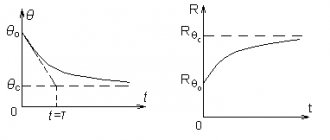
The resistance of NTC thermistors decreases when heated, their TCR is negative. The dependence of resistance on temperature is shown in the graph below.
Here you can see that when heated, the resistance of the NTC thermistor decreases.
Such thermistors are made from semiconductors. The principle of operation is that with increasing temperature, the concentration of charge carriers increases, electrons move into the conduction band. In addition to semiconductors, transition metal oxides are used.
Pay attention to such a parameter as the beta coefficient. Taken into account when using a thermistor to measure temperature, for averaging a graph of resistance versus temperature and performing calculations using microcontrollers
You can see the beta equation for approximating the thermistor resistance curve below.
Interesting: in most cases, thermistors are used in the temperature range of 25-200 degrees Celsius. Accordingly, they can be used for measurements in these ranges, while thermocouples also operate at 600 degrees Celsius.
Where is it used?
Thermistors with negative TCR are often used to limit the starting currents of electric motors, starting relays, to protect against overheating of lithium batteries and in power supplies to reduce the charging currents of the input filter (capacitive).
The diagram above shows an example of using a thermistor in a power supply. This application is called direct heating (when the element itself heats up when current flows through it). On the power supply board, the NTC resistor looks like this.
In the figure below you can see what an NTC thermistor looks like. It can differ in size, shape, and less often, color; the most common are green, blue and black.
Limiting the starting current of electric motors using an NTC thermistor has become widespread in household appliances due to its ease of implementation. It is known that when starting an engine, it can consume current several times or tens of times higher than its rated consumption, especially if the engine is not started at idle, but under load.
The operating principle of this scheme:
When the thermistor is cold, its resistance is high, we turn on the motor and the current in the circuit is limited by the active resistance of the thermistor. This element gradually heats up and its resistance drops, and the engine returns to operating mode. The thermistor is selected in such a way that when hot, the resistance is close to zero. In the photo below you see a burnt thermistor on the board of the Zelmer meat grinder, where this solution is used.
The disadvantage of this design is that when restarting, when the thermistor has not yet cooled down, there is no current limitation.
There is an unusual amateur use of a thermistor to protect incandescent lamps. The diagram below shows an option for limiting the current surge when such light bulbs are turned on.
If a thermistor is used to measure temperature, this mode of operation is called indirect heating, i.e. it is heated by an external heat source.
Interesting: thermistors have no polarity, so they can be used in both direct and alternating current circuits without fear of polarity reversal.
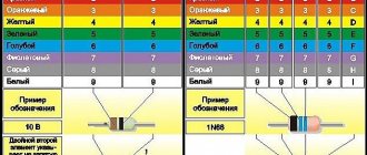
Marking
Thermistors can be marked either alphabetically or contain color markings in the form of circles, rings or stripes. At the same time, there are many ways of letter marking - it depends on the manufacturer and the type of specific element. One of the options:
In practice, if it is used to limit the inrush current, disk thermistors are most often found, which are marked as follows:
5D-20
Where the first number indicates the resistance at 25 degrees Celsius - 5 Ohms, and “20” is the diameter, the larger it is, the more power it can dissipate. You can see an example of this in the figure below:
To decipher the color markings, you can use the table shown below.
Due to the abundance of marking options, you can make a mistake in decoding, so for accurate decoding it is better to look for technical documentation for a specific component on the manufacturer’s website.
Design
The simplest thermistor consists of a temperature-sensitive element, platinum electrodes and nickel leads. This entire structure is enclosed in a sealed housing (the structure diagram is shown in Figure 2).
Metal oxides are used as heat-sensitive materials. To protect the structure, a glass, plastic or metal case is used.
Rice. 2. Design of a simple thermistor
In some cases, copper or platinum is used as the resistive material. These materials have high TCR values for metals in the operating temperature range. However, their use is limited due to the high cost of platinum and its nonlinear transformation.
The use of copper thermistors is limited by the low corrosion resistance of copper. Due to the high thermal conductivity of this metal, copper-based resistive elements are found in models with indirect heating. Suitable for temperatures not exceeding 180 ºC.
Another disadvantage of metal thermal resistances is their inertia, which can reach several minutes. Such designs are not very suitable for maintaining the thermal regime of electrical appliances, but they are ideal as sensors for measuring temperature.
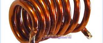
In order to reduce thermal inertia, thermistors are made of microwires, which are enclosed in a glass bulb (see Fig. 3). Such sensors are well sealed, stable, and their inertia does not exceed fractions of seconds.
Figure 3. Thermistor design in a glass bulb
Types of sensors based on semiconductor materials have become widespread. When semiconductors are heated, these materials become saturated with electrons and holes, which leads to a decrease in resistance.
There are designs of flat thermistors (Fig. 4), as well as semiconductor thermistors with a complex structure of the resistive element.
Rice. 4. Design of flat thermistor
Today, more and more often you can find boards on which the SMT mounting method is used. For these purposes, the industry produces SMD thermistors of various ratings (see Fig. 5).
Rice. 5. Thermistors for microelectronics
In most designs, the thermistor element is manufactured using powder metallurgy. For these purposes, the following materials are used:
- chalcogenides;
- metal oxides;
- halides and others.
The outline of resistive elements can be in the form of beads, rods, tubes, plates, etc.
Whatever design you choose, the principle of operation remains the same - the dependence of resistance on temperature. The products differ only in parameters.
Classification of resistors
Three surface mount (SMD) resistors of different values soldered onto a PCB
Resistors are elements of electronic equipment and can be used as discrete components or as components of integrated circuits. Discrete resistors are classified by purpose, type of current-voltage characteristic, method of protection and installation method, nature of resistance change, and manufacturing technology.
By purpose:
- general purpose resistors;
- resistors for special purposes: high-resistance (resistance from tens of MOhms to units of TOhms, operating voltages 100-400 V);
- high-voltage (operating voltage - tens of kV);
- high-frequency (have small inductance and capacitance, operating frequencies up to hundreds of MHz);
- precision and ultra-precision (increased accuracy, tolerance 0.001 - 1%).
By the nature of the change in resistance:
| Fixed resistors (for wall-mounted installation). | Variable resistor. | Trimmer resistors. | Precision multi-turn trimmer resistor. |
- fixed resistors;
- variable adjustment resistors;
- variable tuning resistors.
According to the method of protection against moisture:
- unprotected;
- varnished;
- compounded;
- pressed into plastic;
- sealed;
- vacuum
By installation method:
- for printed circuit installation;
- for wall-mounted installation;
- for microcircuits and micromodules.
According to the type of current-voltage characteristic:
- linear resistors;
- nonlinear resistors: varistors - resistance depends on the applied voltage;
- thermistors - resistance depends on temperature;
- photoresistors - resistance depends on illumination;
- strain gauges - resistance depends on the deformation of the resistor;
- magnetoresistors - resistance depends on the strength of the magnetic field.
- memristors (being developed) - the resistance depends on the charge flowing through it (the integral of the current during operation).
By type of conductive elements used:
| Wirewound resistor with tap. | Film carbon resistor (part of the protective coating has been removed to demonstrate the conductive layer). |
- Wirewound resistors. They are wound from wire or tape with high resistivity onto any frame. Usually have significant parasitic inductance. To reduce parasitic inductance, they are almost always made with bifilar winding. High-resistance small-sized wirewound resistors are sometimes made from microwire. Other types of resistors are called non-wire resistors.
- Non-wire resistors. A resistive element is a volumetric structure of a physical body or surface layer formed on insulating parts (a thin film of a metal alloy or composite material with a high resistivity, low thermal resistance coefficient, usually deposited on a cylindrical ceramic core). The ends of the core are equipped with pressed metal caps with wire leads for installation. Sometimes, to increase resistance, a helical groove is made in the film to form a helical configuration of the conductive layer. These are now the most common type of resistors for through-hole mounting on printed circuit boards. Resistors are made using the same principle as part of a hybrid integrated circuit: in the form of metal or composite films deposited on a usually ceramic substrate by vacuum deposition or screen printing.
By type of materials used:
- Carbon resistors. They are produced in film and volumetric forms. Films or resistive bodies are mixtures of graphite with organic or inorganic substances.
- Metal film or metal oxide resistors. A thin metal strip is used as a resistive material.
- Composite resistors.
- Wirewound resistors.
- Integral resistor. A resistive element is a lightly doped semiconductor formed in a microcircuit crystal in the form of a usually zigzag channel, isolated from other circuits of the microcircuit by a pn junction. Such resistors have a large nonlinearity of the current-voltage characteristic. They are mainly used as part of integrated monocrystalline microcircuits, where it is fundamentally impossible to use other types of resistors.
Thermistor operating mode
Depending on the design intent, thermistors can operate in systems with different temperature conditions. However, each model has its own nominal temperature scale.
On this basis they can be classified as follows:
- low-temperature class thermistors (up to 170 K);
- products of medium temperature class (used in the temperature range 170 – 510 K);
- high-temperature class models (ranging from 570 K and above).
Thermistors are included in a separate class, capable of operating at temperatures from 900 to 1300 K. These models are used as temperature sensors of various heating elements.
All thermistors can withstand significant current loads. True, when operating in harsh thermal cyclic modes, their thermoelectric characteristics may change. Over time, changes will affect the nominal resistance and resistance coefficient.
Thermistor Series
The following series of direct heated thermistors were produced by the domestic industry.
- ST1 – copper-manganese thermistors (formerly MMT);
- ST2 – cobalt-manganese thermistors (formerly KMT);
- ST3 – copper-cobalt-manganese thermistors;
- ST4 – nickel-cobalt-manganese thermistors;
- ST5 – posistors based on barium titanium doped with germanium;
- ST6 – posistors based on barium titanate (BaTiO3);
- ST8 – thermistors based on vanadium sesquioxide and a number of polycrystalline solid solutions in V2O3-Me2O3 systems (Me=Ti; Al, Cr);
- ST9 – thermistors based on vanadium dioxide VO2;
- ST10 – PTC posistors based on the (Ba, Sr)TiO3 system;
- ST11 – PTC posistors based on the (Ba, Sr)(Ti, Sn)O3 system doped with cerium.
Varieties
All thermistors are classified according to the type of heating: direct and indirect. For direct heating, the current of the circuit in which the thermistor is connected is used. Indirect heating is created by third-party circuit sections or thermal elements.
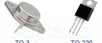
An example of a direct heated thermistor is shown in Fig. 6.
Rice. 6. Directly heated thermistors
Also, depending on whether the resistance increases or decreases when the resistive element is heated, there are two types of thermistors: with a negative TCR and thermistors with a positive resistance coefficient.
NTC.
Semiconductor models (thermistors) have a negative coefficient of temperature resistance. This means that they reduce the nominal resistance (reading at 25 ºC) as a result of heating. The temperature coefficient shows by what percentage the resistance of a resistive element decreases when the heating temperature increases by 1 ºC.
Negative coefficient NTC thermistors are typically used in the operating temperature range of 25 ºC to 200 ºC. For temperatures above 600 ºC, thermocouples are used.
PTC.
PTC thermistors have positive temperature coefficients. These PTC thermistors are often called posistors to emphasize the positive temperature coefficient. By this term we mean a thermistor, the resistance of which increases with increasing temperature.
Thermistors
Here are the characteristics of small-sized thermistors that can be used in PC temperature control devices and designs you develop.
Thermistors or thermistors (TR) are semiconductor resistors with a nonlinear Volt-Ampere Characteristic (VAC), which have a clear dependence of electrical resistance on temperature. Thermistors with negative and positive Temperature Coefficient of Resistance (TCR) are produced.
Nominal resistance Rн
- electrical resistance, the value of which is indicated on the case or indicated in the regulatory documentation, measured at a certain ambient temperature (usually 20ºC). The values are set according to row E6 or E12.
Temperature coefficient of resistance TKS
- characterizes, as usual, a change (reversible) in resistance by one degree Kelvin or Celsius.
The maximum permissible power dissipation
P max
is the highest power that a TR can dissipate for a long time without causing irreversible changes in characteristics. However, its temperature should not exceed the maximum operating temperature.
Temperature sensitivity coefficient B
— determines the nature of the temperature dependence of this type of TR. Known as the constant B, which depends on the physical properties of the semiconductor material from which the temperature-sensitive element is made.
Time constant t - characterizes thermal inertia.
It is equal to the time during which the resistance of the TR changes by 63% when it is transferred from an air environment with a temperature of 0ºC to an air environment with a temperature of 100ºC.
Thermistors with negative TCS
| Type | Range of nominal resistances at 20ºС, kOhm | Tolerance % | Maximum power 20ºС, mW | Operating temperature range, ºС | TKS at 20ºС, %/ºС | Constant V, K | Time constant t, sec | Type and scope |
| KMT-1 | 22 -:- 1000 | ±20 | 1000 | -60-:-180 | 4,2-:-8,4 | 3600 -:-7200 | 85 | C, T measurements |
| KMT-4 | 22-:-1000 | ±20 | 650 | -60 -:- 125 | 4,2-:-8,4 | 3600 -:-7200 | 115 | C, T measurements |
| KMT-8 | 0,1-:-10 | ±10,±20 | 600 | -60-:-+70 | 4,2-:-8,4 | 3600-:-7200 | 909 | Thermal compensation |
| KMT-10 | 100-:-3300 | ±20 | 250 per current 2sec | 0-:-125 | >4,2 | >3600 | 75 | C, Control T |
| KMT-11 | 100 -:-3300 | ±20 | 250 per current 2sec | 0-:-125 | >4,2 | >3600 | 10 | C, Control T |
| KMT-12 | 100Ohm-:-10 | ±30 | 700 | -60 -:-125 | 4,2 -:-8,4 | 3600-:-7200 | — | D, Meas. - T Comp. |
| KME-14 | 510,680, 910 Ohm 160, 200, 330 KOhm 4.3, 75 MOhm at 150°C | ±20 | 100 | -10-:-300 | 2,1-:-2,5 3,4-:-4,2 3,5-:-4,3 | 3690-:-4510 6120-:-7480 6300-:-7700 | 10-:-60 | B, T measurements |
| KMT-17v | 0,33-:-22 | ±10,±20 | 300 | -60-:-155 | 4,2-:-7 | 3600-:-6000 | 30 | D, T measurement |
| MMT-1 | 12 — :- 220 | ±20 | 500 | -60 -:- 125 | 2,4 -:- 5 | 2060 -:- 4300 | 85 | C, T measurements |
| MMT-4 | 1-:-220 | ±20 | 560 | -60 -:- 125 | 2,4 -:- 5 | 2060 -:- 4300 | 115 | C, T measurements |
| MMT-6 | 10-:-100 | ±20 | 50 | -60 -:- 125 | 2,4-:-5 | 2060-:-4300 | 35 | C, T measurement |
| MMT-8 | 1 Ohm -:- 1 | ±10,±20 | 600 | -60 -:- 70 | 2,4 -:- 4 | 2060-:-3430 | 900 | Thermal compensation |
| MMT-9 | 10 Ohm -: -4.7 | ±10,±20 | 900 | -60 -:- 125 | 2,4-:-5 | 2060-:-4300 | — | D |
| MMT-12 | 0,0047 — 1 | ±30 | 700 | -60 -:- 125 | 2,4-:-4 | 2060-3430 | — | D, Thermal compensation |
| MMT-15 | 750Ohm-:-1.21 | — | — | -60 -:- 125 | 2,6-:-4 | 2230-:-3430 | D | |
| MME-13 | 0,01 — 2,2 | ±20 | 600 | -60 -:- 125 | 2,4-:-5 | 2060-4300 | — | D, Thermal compensation |
| PT-1 | 400 ohm -: -900 ohm | — | — | -60 -:- 150 | 4,1-:-5,1 | 3500-:-4400 | — | D, T measurement |
| PT-2 | 80 Ohm -:- 400 Ohm | ±20 | — | -60 -:- 150 | 4,4-:-4,8 | 3800-:-4100 | — | D, T measurement |
| PT-3 | 400 Ohm -:- 900 Ohm | ±20 | — | -60 -:- 150 | 4,3-:-4,8 | 3700-:-4700 | — | D, T measurement |
| PT-4 | 0,6-:-0,8 | — | — | -60-:-150 | 4,1-:4,9 | 3500-:-4200 | — | D, T measurement |
| ST3-14 | 1,5; 2,2 | ±20 | 30 | -60-:-125 | 3,2-:-4,2 | 2600-:-3600 | 4 | B, T measurement |
| MKMT-16 | 2,7; 5,1 | ±30 | 40 | -60-:-125 | 3,8-:-4,2 | 3250-:-3600 | 10 | B, T measurement |
| ST1-18 | 1.5; 2.2; 22; 33; 1500; 2200 at 150ºС | ±20 | 45 | -60-:-300 | 2.25-:-5 at 150ºС | 4050-:-9000 | 1 | B, T measurement |
| ST3-1 | 0,68 -:- 2,2 | ±10, ±20 | 600 | -60 -:- 125 | 3,35 -:- 3,95 | 2870-:-3395 | 85 | C, T measurements |
| ST3-14 | 1,5; 2,2 | ±20 | 30 | -60 -:- 125 | 3,2-:-4,2 | 2600-:-3600 | 4 | B, T measurement |
| ST3-17 | 33Ohm-:-330 Ohm | ±10, ±20 | 300 | -60 -:- 100 | 3-:-4,5 | 2580-:-3850 | 30 | D, Meas. - T Comp. |
| ST3-18 | 0,68-:-3,3 | ±20 | 15 | -90-:-125 | 2,6-:-4,1 | 2250-:-3250 | 1 | B, T measurement |
| ST3-3 | 6,8; 8,2 | ±10 | 150 | -90-:-125 | 2,8 -:- 3,2 | 1200 -:- 2400 | 35 | C, T measurements |
| ST1-2 | 82, 91,100, 110 ohm | ±5 | 700 | -60-:-+85 | 4,4-:-4,9 | 3800-:-4200 | 60-:-100 | D, T measurement |
| ST1-17 | 330Ohm-:-22 | ±10, ±20 | 300 | -60-:-155 | 4,2-:-7 | 3600-:-6000 | 30 | D, Meas. - T Comp. |
| ST1-19 | 3,3-:-10 | ±20 | 60 | -60-:-300 | 2.35-:-4 at 150ºС | 4230-:-7200 | 3 | B, T measurement |
| ST1-30 | 33 | — | <120 mA heating current | -60-:-85 | 4,2-:-5,1 | 3600-:-4400 | 6-:-12 | Measuring velocities of gases and liquids |
| ST3-19 | 2,2; 10; 15 | ±20 | 45 | -90-:-125 | 3,4-:-4,5 | 2900-:-3850 | 3 | B, T measurement |
| ST3-22 | 1 at 25°C | ±30 | 8 | -60-:-85 | 3,1-:-4,2 | 2700-:-3700 | 15 | B, T measurement |
| ST3-23 | 2.2 ohm -: -4.7 ohm | ±10, ±20 | — | 0-:-125 | 3,1-:-3,8 | 2600-:-3200 | — | D, Thermal compensation |
| ST3-25 | 1,5-:-6,8 | ±20 | 8 | -100-:-125 | 3,05-:-4,3 | 2500-:-3700 | 0,4 | B, T measurement |
| ST3-28 | 150Ohm-:-3.3 | ±20 | — | -60 -:- 125 | 3-:-4,6 | 2580-:-3970 | — | D, Thermal compensation |
| ST4-2 | 2,1-:-3,0 | — | — | -60 -:- 125 | 4,2-:-4,8 | 3170-:-4120 | — | D, Meas. T, auto-tracton engines |
| CT4-15 | 880 Ohm -1.12 | — | — | -60 -:- 125 | 3,4 -:-3,8 | 2350- 3250 | — | D, Meas. T, auto-tracton engines |
| ST4-16 | 10-:-27 | ±5; ±10 | 150 | -60-:-155 | 3,45-:-4,45 | 2720-:-3960 | 30 | B, T measurement |
| ST4-16A | 6,8; 10; 15 | ±1; ±2; ±5 | 180 | -60-:-+200 | 4,05-:-4,45 | 3250-:-4100 | B, T measurement | |
| ST4-17 | 1,5-:-2,2 | ±10 | 500 | -80-:-+100 | 3,8-:-4,2 | 3260-:-3600 | 30 | D, T measurement |
| ST9-1A | 0,15-:-450 | — | 800 | -60-:-+100 | — | 1600-:-2000 | 110 | C, Thermostats |
| TR-1 | 15; 33 | ±10; ±20 | 20; 50 | -60-:-+155 | 3,8-:-4,4 | 3200-:-3900 | 5-:-10 | B, T measurement |
| TR-2 | 15; 33 | ±10; ±20 | 20; 50 | -60-:-+155 | 3,8-:-4,4 | 3200-:-3900 | 5-:-10 | B, T measurement |
| TR-3 | 1,2; 12 | ±10 | 1000 | -60 -:- 125 | 3,9-:-4,8 | 3470-:-4270 | — | D, Reg. sensor T |
| TR-4 | 1 | ±20 | 70 | -60-:-+200 | 1,8-:-2,2 | 1500-:-1960 | 3 | B, T measurement |
TRs have different designs:
| Design | Designation | Appearance |
| rod | WITH | |
| disk | D | |
| beaded | B |
New! Thermistors based on single crystals of semiconductor diamond, type TPA-1, TPA-2.
These are new semiconductor devices that have significant advantages compared to previously produced thermistors.
The use of semiconductor diamond single crystals as thermosensitive elements (TSEs) has significant advantages, which are determined by the following unique properties:
- complete absence of diffusion effects (operability) up to a temperature of about 1000°C;
- exceptional resistance to aggressive environments and radiation;
- absolute hardness,
- low inertia.
| parameter | at | dimension | magnitude | Note | |
| TPA-1 | TPA-2 | ||||
| Nominal resistance | 25°С | kOhm | 0,01 — 10000 | Produced according to: DILS.434121.001 TU, OZh0468051TU | |
| Temperature sensitivity coefficient | -200…+300°С | TO | 300…2500 | 600…6000 | |
| Temperature coefficient of resistance | 25°C | %/deg | -0,2…-2,3 | -0,5…-0,6 | |
| Maximum power dissipation | — | mW | 500 | ||
| Operating temperature range | — | WITH | -200…+330 | ||
| Time constant | — | sec | 1…5 | ||
| Peak acceleration of multiple mechanical shock | — | g | 150 | ||
| Increased atmospheric pressure | — | Pa/kg*cm2 | 297200/3 | ||
| Atmospheric condensed precipitation | — | frost, dew | |||
| Special factors | — | group | 4U | ||
Thermistors of type TRA-1 and TRA-2 can be used in the following electronic devices:
- analogue and digital thermometers with a measurement range from -60°C to 300°C (and operation at maximum temperatures for 500 hours did not lead to a noticeable change in calibration);
- temperature-compensated frequency generators;
- thermostats with different heater power;
- liquid and gas flow meters of hot-wire type;
- minimum liquid level indicators,
- and others where TR with negative TCS is used.
The glass body and massive crystal compared to diamond (~0.2...0.3 mm) significantly limit the maximum operating temperature of the TPA (<400°C) and thermal inertia (> 1 s). In this case, the use of copper wire with a diameter of 0.1 mm as leads makes it possible to reduce the time constant by approximately 2 times.
Experimental designs of unpackaged diamond thermistors are being developed, in which the crystal size is 0.5...0.6 mm, and the diameter of the silver leads is 0.05 - 0.1 mm. For such thermistors, the maximum operating temperature increases to 600°C, and at the same time the thermal inertia decreases by an order of magnitude.
, 601655, Vladimir region, Alexandrov, st. Institutskaya 24, Polyansky E.V.
Directly heated thermistors are voltage stabilizers.
| Type | Nom. voltage, V | Stabilization range, V | Max. voltage changes, V | Average worker current, ma | Current working area, mA | Limit current (2s), ma |
| TP 2/0.5 | 2 | 1,6-:-3 | 0,4 | 0,5 | 0,2-:-2 | 4 |
| TP 2/2 | 2 | 1,6-:-3 | 0,4 | 2 | 0,4-:-6 | 12 |
| TP 6/2 | 6 | 4,2-:-7,8 | 1,2 | 2 | 0,4-:-6 | 12 |
Thermistors with positive TCS, posistors.
| Type | Range of nominal resistances at 20ºС, kOhm | Max. Power, W | Operating temperature range, ºС | The temperature range is positive. TKS, ºС | Max. TKS at 20ºС, %/ºС | Frequency of measurement resistance in the region positive TCS. | Time constant, sec | Purpose |
| ST5-1 | 0,02-:-0,15 | 0,7 | -20-:-+200 | 100-200 | 20 | 1000 | 20 | PP alarm |
| ST6-1A | 0,04-:-0,4 | 1,1 | -60-:-+155 | 40-:-155 | 10 | 1000 (at 25-140°C) | 20 | -«- |
| ST6-1B | 0,18; 0,27 | 0,8 | -60-:-+125 | 20-:-125 | 15 | 1000 (at 25-100°C) | 20 | -«- |
| ST6-4G | 5-:-25 | 0,8 | -60-:-+125 | -20-:-+125 | 2-:-6 | 5-:-15 | 40 | D, T measurement |
| ST6-6B | 5-:-25 | 2,5 | -60-:-+125 | 20-:-125 | 15 | 1000 | 180 | — |
| ST10-1 | 30-:-300 | 0,5 | -60-:-+175 | 100-:-175 | — | — | — | Thermal compensation |
| ST5-2-127V | 15-:-35 Ohm | 3 | -60-:-+60 | 60-:-150 | 15 | 10000 (at 25-160°C) | — | Demagnetization systems for picture tube masks. |
| ST5-2-220V | 20-:-50 Ohm | 3 | -60-:-+85 | 60-:-150 | 15 | 10000 (at 25-160°C) | — |
If you need parameters for special-purpose thermistors, write.
The reference table in full (pdf format) from the reference book below can be downloaded here.
Reference table “Thermistors based on semiconductor diamond single crystals” in
Literature:
1. Handbook of REA developer and designer, Element base, Book II, Moscow, publishing house "Pribor" LLP, 2000?
Based on materials from the reference book and other sources, prepared by A. Sorokin, 2008.
Technical specifications
A wide variety of thermal resistance models are dictated by the needs of the modern electronics industry. The technical parameters of semiconductor-type products make it possible to fully satisfy the demand of manufacturers of radio-electronic and electrical devices.
The main parameters include:
- nominal resistance of the thermistor measured at a temperature of 25 ºC;
- power dissipation (that is, the maximum current at which the stability of the thermistor parameters is ensured);
- operating temperature range for which the thermistor is intended;
- TKS.
Semiconductor thermistors have high sensitivity in combination with negative TCR values. They are easy to manufacture, have tiny sizes, and are easily integrated into microcircuits. All these properties make thermistors indispensable in microelectronics.
Semiconductor thermistors are connected via a bridge circuit. This connection allows you to automatically adjust the required parameters of electrical circuits. Sometimes for these purposes it is necessary to use rather complex automation schemes.
The parameters of metal thermistors are more suitable for electrical devices, in particular, they are used as temperature sensors. They can be seen in water heating systems, or in resistance thermometers. These types of sensors (Fig. 7) are very reliable in operation and have a fairly wide measurement range.
Rice. 7. Temperature sensor
Sensors of this type are connected according to a simple scheme. If calibration or temperature adjustment is required, this is usually done manually using a potentiometer. A simple diagram of connecting a temperature sensor is shown in Fig. 8. By changing the voltage with a potentiometer, you can influence the TCR value. You can visually control the temperature using an ammeter, the scale of which is graduated in degrees.
Rice. 8. Simple diagram for connecting a thermistor
Basic parameters of thermistors
Nominal resistance is the resistance of the thermistor at a temperature of 25 °C (rarely at 20 °C). Unlike fixed resistors, the nominal value is not taken from a standardized series.
Accuracy (tolerance) is the permissible deviation of the nominal resistance at a temperature of 25 °C. The permissible deviation of modern thermistors is ±1%...±20% (typical values are ±10% and ±20%).
Maximum power dissipation is the maximum power that a thermistor can continuously dissipate without changing its performance characteristics. Unit of measurement is W.
Dissipation factor – power dissipated by the thermistor, at which the temperature of the element increases by 1 °C relative to the ambient temperature. The unit of measurement is mW/K.
Time constant τ (Thermal time constant) – the time during which the thermistor’s own temperature will change by 63.2% of the difference between the initial and final temperatures during an abrupt temperature measurement (for example, when moving the thermistor to a room with a different temperature). Unit of measurement c.
Coefficients A, B, C, D – coefficients of the dependence of resistance on temperature (more details about the dependence are indicated earlier).
Designation on diagrams
In the circuit diagram, the symbols for thermistors are almost the same as the symbols for conventional resistors, but with an oblique line crossing the rectangle. (see Fig. 9). To distinguish the type of thermistor, the letter t with a degree symbol and a “+” or “–” sign is placed at the bottom of this oblique line, depending on the type of product. For example, +tº or –tº.
Rice. 9. Designation on diagrams
Sometimes the value of the thermistor and its temperature range are indicated.
Definition
Resistor comes from the English “resistor” and from the Latin “resisto”, which translated into Russian sounds like “I resist”. In Russian-language literature, the word “resistance” is used along with the word “resistor”. From the name, the main task of this element is clear - to resist electric current.
It belongs to the group of passive elements, because as a result of its operation, the current can only decrease, that is, unlike active elements, passive elements themselves cannot amplify the signal. Which of Kirchhoff’s second law and Ohm’s law means that when current flows across a resistor, the voltage drops, the magnitude of which is equal to the value of the flowing current multiplied by the value of the resistance. Below you can see how resistance is indicated in the diagram:
The symbol on the diagram is easy to remember - it is a rectangle, according to GOST 2.728-74 its dimensions are 4x10 mm. There are designation options for resistors of different dissipation powers.
Marking
There are two ways of marking - alphanumeric and color, in the form of rings and stripes. There are no uniform requirements for letter markings - different manufacturers use their own versions of designations. For example, on a disk thermistor there may be the symbols “15D-30”, which means: nominal resistance 15 Ohms, product diameter 30 mm. Here, the diameter value is directly related to the power dissipation - the larger the diameter, the greater the power dissipation of the thermistor.
Note that another manufacturer may mark these same parameters in a completely different way. Therefore, it is better to use the technical documentation of the product manufacturer.
Design and Application
Modern photoresistors are made from lead selenide, lead sulfide, indium antimonide, but most often from cadmium and cadmium selenide and sulfide. The spectral characteristics of cadmium sulfide almost completely coincide with the structure of the human eye. The peak sensitivity wavelength is 560-600 nm, which corresponds to the visible part of the spectrum.
To make an element from cadmium sulfide, highly purified powder is mixed with inert binders. Then, this mixture is sintered and pressed. In a vacuum environment, a thin photosensitive layer is applied to the base with electrodes in the form of a winding path. Then, the base is placed in a transparent shell to protect the photosensitive element. The main area of application of these radio elements is automation; with their help, you can create simple and reliable photo relay circuits without the use of current amplifiers.
Such photo relays are used in control and monitoring systems. In measurement technology, photoresistors are used to measure high temperatures in various technological processes. Photoresistors also have a specified temperature range. If you use the sensor at different temperatures, then it is necessary to introduce clarifying transformations, because the resistance property depends on the external temperature.
To characterize the intensity of light, the physical quantity illumination (designation E) is used, which shows the amount of light flux reaching any surface. The unit of measurement is lux (lx), where 1 lux means that a luminous flux of 1 lumen (lm) falls uniformly on a surface measuring 1 m2. In real life, light almost never falls evenly on a (living) surface and therefore the illumination is greater in the average value. For comparison, here are some illumination examples:
Wave color and wavelength range.
Application
Thermistors are mainly used to protect equipment and various devices from overheating and possible overloads. Less often, the dependence of the resistance stabilizes the operation of the heating element.
Examples of using:
- protection of electric motors from overheating;
- thermal protection of transformer windings;
- in demagnetization systems for picture tubes and old monitor models;
- in electronic circuits of modern cars.
Most circuits use the ability of thermistors to convert internal energy into an electrical signal that is read by automation.
In heating devices, a thermistor is quite often used as a self-resetting fuse. Its resistance increases when a critical temperature is reached and, as a result, the electrical circuit opens.
After cooling, the device restores functionality. The areas of application can be listed for a very long time, but these examples also show how popular thermistors and thermistors have turned out to be.
What is a resistor
The simplest definition looks like this: a resistor is an element of an electrical circuit that resists the current flowing through it. The name of the element comes from the Latin word “resisto” - “I resist”; radio amateurs often call this part “resistance”.
Let's look at what resistors are and what resistors are needed for. Answers to these questions imply familiarity with the physical meaning of the basic concepts of electrical engineering.
To explain the principle of operation of a resistor, you can use an analogy with water pipes. If you somehow impede the flow of water in a pipe (for example, by reducing its diameter), an increase in internal pressure will occur. By removing the obstacle, we reduce the pressure. In electrical engineering, this pressure corresponds to voltage - by making it difficult for the flow of electric current, we increase the voltage in the circuit, reducing the resistance, we also lower the voltage.
By changing the diameter of the pipe, you can change the speed of water flow; in electrical circuits, by changing the resistance, you can regulate the current strength. The amount of resistance is inversely proportional to the conductivity of the element.
The properties of resistive elements can be used for the following purposes:
- converting current into voltage and vice versa;
- limiting the flowing current to obtain its specified value;
- creation of voltage dividers (for example, in measuring instruments);
- solving other special problems (for example, reducing radio interference).
You can use the following example to explain what a resistor is and why it is needed. The familiar LED glows at low current, but its own resistance is so low that if the LED is placed directly in the circuit, then even at a voltage of 5 V the current flowing through it will exceed the permissible parameters of the part. From such a load the LED will immediately fail. Therefore, a resistor is included in the circuit, the purpose of which in this case is to limit the current to a given value.
Watch this video on YouTube
All resistive elements belong to passive components of electrical circuits; unlike active ones, they do not release energy into the system, but only consume it.
Having understood what resistors are, it is necessary to consider their types, designation and markings.
Application area
The use of devices depends on their cost and measurement accuracy. More expensive posistors are used in complex industries, and also as fuses. For example, they are connected to an executive relay; in case of heating, the circuit turns off. Thermistors are much more affordable, which allows them to be widely used in everyday life.
Air temperature sensor
When properly calibrated, the NTC resistor can be used to test the heating of the surrounding air. In this case, measurement accuracy, as in production, is not required - adjustment in steps of 1 degree Celsius is sufficient.
Homemade air temperature sensor
Car temperature sensor
A popular method of application is to protect the car engine from overheating. The TP is connected to a relay, which turns off the engine if there is a threat of overheating. With sufficient knowledge, you can connect the device to the on-board computer to display the temperature on the display.
Fire sensor
From a thermistor and bimetallic elements of the starter, you can create a structure similar to a fire alarm. Simple bead TRs are suitable for this. The sensor can also work if it is necessary to exclude triggering by smoke, for example, cigarette smoke.
Thermistor as a starting current regulator
There are a number of appliances that are susceptible to excessive currents when first started: lamps, motors and transformers. To limit them, a thermistor is built into the circuit. Instead of sudden jumps, the current is adjusted according to the load as the thermistor heats up and the resistance decreases.