The resistor is the most common part in electronic designs, sometimes taking up up to 70% of all electronic components. Officially, in reference books, a resistor is an element of an electrical circuit that creates resistance to passing current. In general, any radio-electronic element has resistance, from a light bulb and a piece of wire, to electric motors, transistors and microcircuits; moreover, absolutely all materials on earth have resistance. To estimate the value of resistance, a special unit of measurement, Ohm or Ω, was introduced (named after the German scientist Georg Simon Ohm
).
To assemble a radio-electronic device, you can pre-make a DIY KIT kit using the link.
Types of resistors
A resistor is an electronic component in which the resistance is concentrated in a small volume of some material. Depending on the material from which the resistor is made and the manufacturing method, they are divided into the following types:
- wirewound resistors
- made of high-resistance wire wound around a frame; - metal film resistors
- made by sputtering metal with high resistivity onto a ceramic frame; - metal foil resistors
- made of thin metal foil with high resistivity; - carbon resistors
- made of graphite; - semiconductor resistors
- made of lightly doped semiconductor.
As for any unit of measurement, so for the Ohm there are multiple and submultiple units of measurement. The most commonly used: micro-ohm, mi-ohm, kilo-ohm, mega-ohm, giga-ohm. These units are formed using standard prefixes.
| Multiples | Dolnye | ||||||
| Magnitude | Name | Designation | Magnitude | Name | Designation | ||
| 101 Ohm | decaom | yesOhm | daΩ | 10-1 Ohm | deciom | house | dΩ |
| 102 Ohm | hectoom | gOhm | hΩ | 10-2 Ohm | centiom | cOhm | cΩ |
| 103 Ohm | kiloohm | kOhm | kΩ | 10-3 Ohm | milliohms | mOhm | mΩ |
| 106 Ohm | megaohm | MOhm | MΩ | 10-6 Ohm | microohm | µOhm | μΩ |
| 109 Ohm | gigaohm | Gohm | GΩ | 10-9 Ohm | nanoohm | nOhm | nΩ |
| 1012 Ohm | teraom | Volume | TΩ | 10-12 Ohm | picohm | pOhm | pΩ |
| 1015 Ohm | petaom | POM | PΩ | 10-15 Ohm | femtoom | fOhm | fΩ |
| 1018 Ohm | exaom | Eohm | EΩ | 10-18 Ohm | attoom | aOhm | aΩ |
| 1021 Ohm | zettaom | ZOm | ZΩ | 10-21 Ohm | zeptoom | ZOhm | zΩ |
| 1024 Ohm | Iottaaom | IOhm | YΩ | 10-24 Ohm | ioktoom | iOhm | vΩ |
Resistor markings
Marking of output resistors
A special marking is applied to the resistor body, which contains information about the main parameters of the resistor (at least the nominal resistance and tolerance). Marking can be done in text (text code) or color (color code) in accordance with GOST 28883-90 “Codes for marking resistors and capacitors” (in the literature you can also find references to the canceled GOST 28364-89).
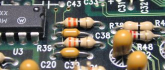
Resistors with the same nominal resistance of 470 Ohms, but with different types of markings: text on the bottom and color on the top
According to GOST 28883-90, the text code must consist of three, four or five characters, one of the characters must be a letter, the rest must be numbers. The letter indicates the multiplier by which the indicated numbers must be multiplied. The decimal point is replaced by a letter. Below are the meanings of the letters:
| Letter | Factor |
| R | 1 ohm |
| K | 103 Ohm (1 kOhm) |
| M | 106 Ohm (1 MOhm) |
| G | 109 Ohm (1GOhm) |
| T | 1012 Ohm (1TOm) |
For example: R47 – 0.47 Ohm; 59R – 59 Ohm; 5K9 – 5.9 kOhm.
A color code is used to indicate the nominal resistance, tolerance and temperature coefficient (if applicable). Strips are applied to the resistor body. Each bar can represent a significant digit, a multiplier, a tolerance, or a temperature coefficient. The first stripe is applied at the edge of the resistor. The remaining stripes are placed so that the first strip can be accurately identified. The number of stripes can be from 3 to 6. The values of the stripes are shown in the table.
| 1 strip | 2 stripes | 3 stripe | 4 strip | 5 strip | 6 strip |
| Meaning number | Meaning number | Factor | |||
| Meaning number | Meaning number | Factor | Accuracy | ||
| Meaning number | Meaning number | Meaning number | Factor | Accuracy | |
| Meaning number | Meaning number | Meaning number | Factor | Accuracy | Temperature coefficient |
| Color | Significant figure | Factor | Tolerance, % | Temperature coefficient of resistance, 10-6 °C |
| Silver | — | 10-2 | ± 10 | — |
| Gold | — | 10-1 | ± 5 | — |
| Black | 0 | 1 | — | ± 250 |
| Brown | 1 | 10 | ± 1 | ± 100 |
| Red | 2 | 102 | ±2 | ± 50 |
| Orange | 3 | 103 | — | ± 15 |
| Yellow | 4 | 104 | — | ± 25 |
| Green | 5 | 105 | ± 0,5 | ± 20 |
| Blue | 6 | 106 | ± 0,25 | ±10 |
| Violet | 7 | 107 | ± 0,1 | ± 5 |
| Grey | 8 | 108 | — | ± 1 |
| White | 9 | 109 | — | — |
| No coloring | — | — | ± 20 | — |
You can determine the resistance of a resistor by color marking online using a color marking calculator.
As can be seen from the table, a resistor with three stripes has a tolerance of ± 20%.
The temperature coefficient strip in accordance with GOST 28883-90 is applied using one of the following methods:
- wider sixth stripe;
- broken sixth stripe;
- spiral line.
Marking chip resistors (SMD resistors)
Text markings are used to mark chip resistors. Resistors of size 0402 are not marked due to their small size.
There are two types of marking chip resistors:
- three and four numeric markings - the first two or three numbers indicate the value, the last - the multiplier;
- EIA-96 marking – two numbers and a letter, used to mark resistors from the E96 series. Two digits are a code for three digits, a letter is a multiplier.
EIA-96 code table
| Code | Meaning | Code | Meaning | Code | Meaning | Code | Meaning | Code | Meaning | Code | Meaning |
| 01 | 100 | 17 | 147 | 33 | 215 | 49 | 316 | 65 | 464 | 81 | 681 |
| 02 | 102 | 18 | 150 | 34 | 221 | 50 | 324 | 66 | 475 | 82 | 698 |
| 03 | 105 | 19 | 154 | 35 | 226 | 51 | 332 | 67 | 487 | 83 | 715 |
| 04 | 107 | 20 | 158 | 36 | 232 | 52 | 340 | 68 | 499 | 84 | 732 |
| 05 | 110 | 21 | 162 | 37 | 237 | 53 | 348 | 69 | 511 | 85 | 750 |
| 06 | 113 | 22 | 165 | 38 | 243 | 54 | 357 | 70 | 523 | 86 | 768 |
| 07 | 115 | 23 | 169 | 39 | 249 | 55 | 365 | 71 | 536 | 87 | 787 |
| 08 | 118 | 24 | 174 | 40 | 255 | 56 | 374 | 72 | 549 | 88 | 806 |
| 09 | 121 | 25 | 178 | 41 | 261 | 57 | 383 | 73 | 562 | 89 | 825 |
| 10 | 124 | 26 | 182 | 42 | 267 | 58 | 392 | 74 | 576 | 90 | 845 |
| 11 | 127 | 27 | 187 | 43 | 274 | 59 | 402 | 75 | 590 | 91 | 866 |
| 12 | 130 | 28 | 191 | 44 | 280 | 60 | 412 | 76 | 604 | 92 | 887 |
| 13 | 133 | 29 | 196 | 45 | 287 | 61 | 422 | 77 | 619 | 93 | 909 |
| 14 | 137 | 30 | 200 | 46 | 294 | 62 | 432 | 78 | 634 | 94 | 931 |
| 15 | 140 | 31 | 205 | 47 | 301 | 63 | 442 | 79 | 649 | 95 | 953 |
| 16 | 143 | 32 | 210 | 48 | 309 | 64 | 453 | 80 | 665 | 96 | 976 |
EIA-96 Multiplier Table
| Code | Z | Y or R | X or S | A | B or H | C | D | E | F |
| Factor | 0.001 | 0.01 | 0.1 | 1 | 10 | 100 | 1000 | 10000 | 100000 |
You can determine the resistance of a chip (SMD) resistor using the SMD resistor marking calculator.
If 0 is marked on the SMD resistor, this is a jumper.
Basic parameters of resistors
Each resistor has a number of parameters by which it is characterized. The most significant are: nominal resistance, permissible deviation, permissible power dissipation, temperature coefficient of resistance (TCR). There are other parameters by which a resistor is evaluated, but they are quite specific and their evaluation is important only in a few cases.
Nominal resistance
is indicated on the resistor body in the form of markings and the resistance value is written in Ohms.
Tolerance
from the nominal value depends on the accuracy class. There are three main classes of resistor accuracy:
- 1 class
with a deviation from the nominal value of 5% (
E24
); - Class 2
with a deviation from the nominal value of 10% (
E12
); - Class 3
with a deviation from the nominal value of 20% (
E6
).
Also available are high-precision resistors with tolerances of 0.01%; 0.02%; 0.05%; 0.1%; 0.2%; 0.5%; 1%; 2% (nominal series E196, E96, E48
).
The next characteristic is the permissible power dissipation
, which can be dissipated (released) on the resistor while maintaining its parameters within the nominal limits for a long time (service life). According to this parameter, resistors can have a value from 0.01 to 500 W. In symbol symbols inside circuit diagrams, power dissipation is indicated using horizontal, vertical, and slanted lines within the resistor rectangle.
Temperature coefficient of resistance (TCR)
is a parameter that characterizes
the change in resistance
when the ambient temperature changes by 1 °C. For conventional resistors, the TKS is negative. Positive, only for carbon resistors it is negative.
- Temperature noise coefficient - almost everyone has it. There may be others, but these main ones are almost always present.
They are measured in relative units, which show how much and where a given characteristic of a radio component changes when the temperature changes by 1°.
These can be percent per degree (%/°), ppm per degree (%/°), or parts per million per degree (ppm/°). For TCS, this can be microvolts or nanovolts per degree (μV/° or nV/°). To be absolutely clear:
% - percent
- this is one hundredth (10-2, 0.01 or 1/100) part of some value;
%o - ppm
- this is one thousandth (10-3, 0.001 or 1/1000) part of some value;
ppm (in Russian: million-1)
is one millionth (10-6, 0.000001 or 1/1000000) part of some value. Sometimes the characteristics of radio components change so cleverly depending on temperature that special graphs are drawn for them or complex formulas are written.
4. Now let’s talk about “TK” in more detail:
TCR - temperature coefficient of resistance
Resistors are made from different materials. The simplest of them are wire
.
The temperature dependence of their resistance is linear, the smallest TKS of them have resistors made of constantan (TCS -5) and manganin (TCS -5), so they are used in measuring technology. Very cheap carbon resistors
, type C1-4 or CF.
But their TCS is quite large: from +350 to minus 2500 ppm/°. Therefore, they are mainly used in household equipment that operates in room conditions. Metallized and metal film resistors
, type C2-23, C2-33 (MLT, MT old) or MF.
Their TCS is average: from 15 to 500 ppm/°, maximum up to 1200 ppm/°. Suitable for most applications over a wide temperature range. The most expensive are precision ones
, type C2-29B or RN.
Their TCS is the smallest: from 5 to 300 ppm/°. They are used in measuring equipment or in critical places in conventional equipment where stability of resistance when temperature changes is important, for example in RC filters. In domestic resistors, the TKS group is designated by a letter, which, unfortunately, is indicated only on the factory packaging. Specific designations and values of TKS can be found by looking in reference books or in technical specifications (technical conditions in our opinion or DataSheets in theirs). But they are not available to everyone. Attention!
Nowadays, among imported resistors (usually of unknown origin), there is a substitution of the concept of “nominal tolerance” - i.e.
The precision with which the resistor is made in this case creates a huge TKS. This means that the resistance of this resistor will not go beyond, for example, +/-10% when the temperature changes. This supposed “Tolerance” is indicated on the resistor. Comrades, be careful! There is a class of resistors where, on the contrary, a large TCR is important. These are thermistors or thermistors and resistance thermometers
.
Thermistors or thermistors (sometimes there is a “ posistor
” - a thermistor with a positive TCR) are very widely used in electronic equipment for various purposes, for example: protection of powerful transistors, thermal stabilization of any parts of the circuit, etc. Resistance thermometers are usually made of copper or even platinum wire and are used for accurate temperature measurement in industry.
TKE - temperature coefficient of capacity
The TKE of a capacitor very much depends on the dielectric material between the plates. After all, the slightest temperature change in the thickness of the dielectric causes a very large change in the capacitance of the capacitor. Ceramic capacitors are most susceptible to temperature effects
.
Since it is not possible to completely defeat TKE (and sometimes, on the contrary, the wedge is knocked out with wedge: for example, in an LC circuit, the TKE coil has a positive one, then a capacitor with a negative TKE is installed so that the circuit tuning frequency does not change from the temperature), with ceramic capacitors There are a lot of different TKEs. TKE for ceramic capacitors is so important that it is almost always indicated on the capacitor body in some way. Therefore, we will talk about them in more detail: Domestic designation system TKE (including old and very old)
Note: where the TKE color designation requires 2 colors, then one of them may be the color of the body. TKE groups, designated by the letters “P” (plus) and “M” (minus), have a linear dependence of capacity on temperature. The MP0 group is the most stable - no change in temperature affects the capacitance of the capacitor. But the TKE groups, designated by the letter “N” (nonlinear), have a very tricky dependence of capacitance on temperature, so it’s better to look at them in the picture:
This picture is drawn as an example; for different types of capacitors, these “H” may be curved differently. The main thing is that the capacity of these capacitors with a change in temperature will not change more than the percentage with the letter “H” written.
Capacitors with groups TKE P100 (P120), P33, M47, M75, i.e. with low TKE values are also called thermostable. The TKE MP0 group, as already mentioned earlier, is the most thermostable. Capacitors with groups TKE M750, M1500 (M1300), i.e. with large negative TKE values, are also called thermally compensating (they are placed in the LC circuit for stability). The bourgeoisie have their own notation system, but it is very similar to ours. Instead of the letter "M" they have the Latin letter "N", instead of "P" - "P". They designate the MP0 group as NP0 or C0G. And instead of the letter “H” they have a whole bunch of all sorts of designations: Y5x, X5x, Z5x (x stands for one of the letters: F, P, S, U, V); X7R. These designations are the most common, but different TKE designations are used. Here only branded DataSheets (reference sheets) will help us. To make it easier for us, the approximate correspondence between our and bourgeois notations is as follows:
Connection of resistors
Resistors can be connected in series or in parallel. With sequential
connection, the total resistance will be equal to the sum of the resistances of the individual resistors
Series connection of resistors
With parallel
When connecting resistors, the total resistance will be equal to the sum of the conductivities of these resistors.
Conductivity
is the reciprocal of resistance
Parallel connection of resistors
Online calculator for calculating the connection of resistors.
Features of the selection and use of resistors in power engineering
The apparent simplicity and obviousness of the use of resistors gives developers of power conversion equipment the misleading impression of the small influence of resistors, as extremely simple devices from the point of view of circuit design, on the resulting reliability of the device being developed. However, this is not the case, and the use of resistors, like any other component, requires careful consideration in selecting types and ensuring favorable operating conditions.
To better understand the operating features of resistors, let's turn to basic concepts. A resistor, as an element of an electrical circuit, serves to create resistance to the flow of electric current. Ideally, the operation of a resistor is determined by a fundamental law established by the German physicist Georg Simon Ohm and bearing his name:
where R is the electrical resistance of the circuit section; U is the voltage applied to the circuit section; I is the current flowing in the circuit.
When current flows through a resistor, the energy of the ordered movement of charge carriers is converted into heat and dissipated in the surrounding space due to heat transfer and radiation. The power released in the resistor can be determined by the formula following from Ohm's law:
or
Here P is the power released in the circuit section; R is the electrical resistance of the circuit section; U is the voltage applied to the circuit section; I is the current flowing in the circuit.
The power released in the resistor causes its temperature to rise. The maximum temperature that a resistor can withstand without damage depends on the design of the resistor and the materials used - both the resistive element itself and its fittings. It is the maximum temperature of the hottest section of the resistor that determines the power that the resistor is capable of dissipating.
Depending on the conditions in which the resistor is located (temperature, humidity, ambient air pressure and the speed of its movement), the same dissipated power causes a different increase in the temperature of the device, therefore, when choosing a resistor, it is important not only to determine the allocated power, but also its conditions work. The rated power of the resistor is defined as the power dissipated by the device without exceeding the maximum permissible temperature with natural air cooling at an altitude of 0 m above sea level at an air temperature of 25 ° C.
When operating a resistor, it should be remembered that the released power has a quadratic dependence on the voltage applied to the resistor or on the flowing current (Fig. 1).
Rice. 1. Dependence of the released power on the voltage (current) of the resistor
This means that a small increase in voltage or current in the circuit will cause a significant increase in power dissipation, which can exceed the maximum allowable for the resistor used, which will lead to failure of the device. Therefore, when choosing a resistor, it is important not only to know the rated current and voltage for it, but also to take into account possible long-term deviations, in particular due to fluctuations in the supply voltage.
If the power dissipated by the resistor is constant, then after some time the temperature of the resistor will stabilize (when the amount of heat generated in the resistor becomes equal to the amount of heat given off by the resistor to the environment through radiation, convection and heat transfer from the structure). The larger the physical size of the resistor, the more efficiently the heat transfer process occurs and the lower the equilibrium temperature will be at the same power output. In addition, the efficiency of radiation, convection and heat transfer depends significantly on the resistor design, materials used and cooling conditions.
The values of the maximum power dissipation of resistors given in the reference materials refer to free cooling conditions. Today, there are a number of standards regulating the method for determining the maximum permissible power dissipation of resistors based on the overheating temperature of the hottest section of the resistor. Leading manufacturers of high-power resistors (Danotherm, Ohmite, Arcol, SIR, etc.) usually follow the recommendations of the National Electrical Manufacturers Association (NEMA) and Underwriters Laboratories, Inc. when regulating the power of their devices. (UL). According to these, the maximum permissible power during natural cooling for a resistor of given physical characteristics and dimensions is defined as the power that causes the temperature (measured by a thermocouple) of overheating of the hottest section of the resistor to be 300 °C at an ambient temperature of 40 °C. The measurement is carried out in still air under conditions of free convection and the resistor is removed from the nearest object (in particular, walls, panels, devices) by at least 35 cm.
Slightly different measurement conditions are determined by the MIL-R-26 standard, originally developed for wirewound resistors for military and aerospace applications, and then extended to devices for industrial and commercial use. According to this standard, the maximum heating temperature of the hottest section of the resistor is set to 350 °C at an ambient temperature of 25 °C. Thus, the corresponding superheat temperature is 325 °C.
In Fig. Figure 2 shows average graphs of the overheating temperature of resistors according to various standards depending on the relative power dissipation.
Rice. 2. Dependence of the resistor overheating temperature on the relative power dissipation
To a first approximation, the temperature of a resistor depends on its surface area, and also (to a lesser extent) on a number of other factors, such as the thermal conductivity of the base and coating of the resistor, the radiation efficiency of the surface, the ratio of the resistor's length to its diameter, heat transfer through the terminals and mounting means.
The maximum permissible temperature of the resistor will be determined by the properties of its structural materials and is the limit value, above which the device may become inoperable. In the general case, this value can be used only to calculate the maximum operating modes of the device.
Under normal operating conditions, one should take into account not only and not so much the physical functioning of the resistor, but also other parameters, such as changes in resistance with increasing temperature, heating of devices surrounding the resistor due to the heat generated by it, dependence of resistance on ambient humidity (especially for resistors open types), changes in characteristics under cyclic load, etc.
If the ambient temperature differs (increasingly) from 25 °C (or 40 °C), then the power dissipated by the resistor should be correspondingly reduced to values at which the maximum permissible heating temperature of the device is not exceeded. In Fig. Figure 3 shows graphs of the relative power dissipation of resistors versus ambient temperature according to NEMA, UL and MIL-R-26 (U-EIA) recommendations.
Rice. 3. Dependence of the relative power dissipation of the resistor on the ambient temperature
When constructing these dependencies, it is assumed that the overheating temperature does not depend on the ambient temperature. However, this is not entirely true. An accurate calculation must take into account the increase in radiation efficiency with increasing temperature according to the Stefan-Boltzmann and Wien laws. But the contribution made due to this at low temperatures (up to 1000–1500 °C) is very small, and it can be ignored in the vast majority of design calculations.
For some types of resistors, the reference data indicates the maximum permissible thermal load of the surface. For most types of wirewound resistors, it ranges from 0.7 W/cm2 (for large resistors with a power of more than 150–200 W) to 2 W/cm2 (for small resistors with a power of 10–20 W). This value is convenient to use when calculating the operation of a resistor as a heating element.
Please note that the recommendations for determining the maximum power of resistors do not indicate the location of the resistor relative to the ground surface. But there is a clear indication that the temperature is measured for the hottest section of the resistor. For a horizontally located tubular wirewound resistor with uniform winding of the resistive element, the temperature in the middle of the device can be 1.5–2.5 times higher than the temperature at the ends (depending on the mounting method). When positioned vertically, the maximum heating zone shifts upward by 3–10% of the length of the resistor, and the upper end has a higher temperature than the lower end. This causes a slight increase in mechanical stress in the device structure and may reduce its reliability. Therefore, all other things being equal, you should always prefer the horizontal arrangement of resistors, with the exception of devices specially designed for vertical installation, for example, in heat-sinking housings made of aluminum profiles. For a number of special applications (for example, as a uniform heat source), special resistors are produced with uneven winding of the resistive element (more frequent at the edges and rarer in the middle), in which the temperature is almost constant along the entire length of the device.
Let us consider in more detail the main factors that determine the temperature of the resistor, or, on the other hand, the required value of rated power at which the temperature does not exceed the specified one:
1. Ambient temperature
An increase in ambient temperature causes a corresponding decrease in the permissible overheating temperature and the corresponding dissipation power. The dependence of the relative permissible power dissipation on the ambient temperature is shown above, in Fig. 3. If the ambient temperature is lower than that for which the maximum dissipation power was determined (25 ° C or 40 ° C), then in some cases it is possible to allow the maximum power to increase above the typical value, but in this case it is necessary to further clarify the resistor’s capabilities for working with currents exceeding the rated current. Exceeding the resistor current in this case may not cause an increase in its temperature above the maximum permissible, but the destruction of external and internal contacts (the junction of the resistive element with the terminals) and local overheating and melting of the resistive element.
2. Installation in a closed housing
Installing a resistor in the housing worsens the conditions for heat removal due to radiation (part of the radiation is reflected by the walls of the housing, the rest is emitted both into the surrounding and into the internal space of the housing), as well as due to convection (the housing disrupts the convection flow of air and blocks the access of cold air to resistor). The temperature of the resistor placed in the housing is significantly influenced by the size, wall thickness, their material and the presence of perforations and surface coloring. The deterioration of the operating conditions of the resistor when placed in a housing is clearly demonstrated by the graphs in Fig. 4.
Rice. 4. Dependence of resistor overheating temperature on power when installed in free space and in housings of different sizes
3. Installation of groups of resistors
Resistors mounted at a short distance from each other heat up more during operation than a single resistor with the same power dissipation (on each of the resistors in the group). This occurs due to mutual heating of the resistors by radiation and an increase in the amount of heat per unit volume of cooling air during natural convection. In order to ensure that the temperature of resistors operating in a group does not exceed the permissible value, it is necessary to reduce the power per each of the devices in relation to the maximum permissible for one freely installed resistor. Rice. 5 gives an idea of the order of the required reduction in power dissipation on each of the resistors, depending on the number of resistors in the group and the distances between them.
Rice. 5. Dependence of the permissible power dissipation of each resistor in the group on the number of resistors and the distances between them
4. Altitude
The amount of heat removed from the resistor due to air convection depends on the density of the latter. The thinner the air, the less heat it can remove. As you rise in the atmosphere, the density of the air decreases, which means that the maximum power dissipation of the resistors will decrease. At altitudes above 20,000 m, the air density is already so low that convective heat removal ceases to play any significant role in the overall thermal balance of the resistor and heat is removed only through radiation and heat transfer to structural elements. In Fig. Figure 6 shows a graph of the dependence of the relative power dissipation of the resistor on the height of its placement (above sea level).
Rice. 6. Dependence of the relative permissible power dissipation of the resistor on altitude above sea level
5. Work in pulse modes
If current does not flow through the resistor constantly, but during certain time intervals, and at other times the resistor is de-energized, then the amount of heat generated over a significant period of time will be less than during continuous operation. “Averaging” over time occurs due to the heat capacity of the structure, mounting elements and surrounding air. As a result, the temperature of the resistor does not exceed the maximum permissible even at pulse powers many times higher than the maximum power of continuous mode. The amount of permissible pulse power depends both on the design features of the resistor (heat capacity and thermal conductivity of the structure), and on the pulse duration and the ratio of pulse and pause durations (duty factor). In Fig. Figure 7 shows the relative permissible pulse power dissipation for various types of resistors, determined according to NEMA recommendations for starting and braking resistors.
Rice. 7. Dependence of the relative pulse permissible power dissipation of the resistor on the duty cycle of the current pulses for the standard starting mode of the electric motor
For a number of types of resistors, the pulse power is limited not by permissible overheating, but by the maximum value of the operating current of the resistor, if exceeded, damage to the resistive element and terminals is possible due to local overheating.
Graphs in Fig. 8 give an idea of the process of heating resistors of different types with a current pulse and are plotted in coordinates of the pulse time required to heat the resistor to the maximum permissible temperature and pulse power.
Rice. 8. Dependence of the time required to heat the resistor to the maximum permissible temperature on the relative pulse power dissipation
Using the dependencies presented in Fig. 9, it is possible to determine the ratio of the pulse durations and pauses of the current through tubular resistors, heating the devices to the maximum permissible temperature for various absolute durations and various relative pulse powers (as a percentage of the maximum permissible power dissipation of the continuous mode).
Rice. 9. Dependence of current pulse and pause times and their ratios required to heat the resistor to the maximum permissible temperature on pulse power
The features of pulse modes discussed above relate to typical pulse modes that occur when using resistors in the starting and braking circuits of electric motors, where the times of exposure to significant currents are calculated in units and tens of seconds, and pauses - from units of seconds to many hours.
For pulsed currents of short duration (0.1–0.5 s or less), the pulse characteristics will differ significantly from those given above, since they will be determined to a greater extent by the thermophysical properties of the resistive element rather than by the heat capacity of the entire resistor as a whole. At even shorter pulse durations (less than a few milliseconds), the inductance of the resistor begins to play an important role, increasing the total resistance of the resistor in the region of small times. For use at frequencies above 1–3 kHz (pulse durations less than 1 ms), special resistors are manufactured with bifilar winding, which sharply reduces the resistor’s own inductance, or surface and volume resistors based on conductive films.
6. Forced cooling
Forced blowing of resistors sharply increases the amount of cooling air compared to the natural convective flow and, thereby, makes it possible to increase the efficiency of heat removal. This is a very simple and extremely effective way to increase the permissible power dissipation of resistors. In Fig. Figure 10 shows the dependence of the relative permissible power dissipation on the speed of the air cooling the resistor.
Rice. 10. Dependence of the relative permissible power dissipation of the resistor on the cooling air speed
The effectiveness of this simple measure can be judged by the fact that at an air speed of only 2.5 m/s, the power dissipated by the resistor without overheating is more than twice its maximum power with natural cooling. If resistors operate, for example, in rheostatic braking systems of electric rolling stock, then in order to save energy, it is possible to use not constant blowing, but one associated with the braking process, when fans are connected in parallel with the braking resistor or its outlet. Such cooling circuits for braking resistors are used on a number of mainline electric locomotives of domestic and foreign production.
7. Resistor temperature limitation
In some cases, in order to increase reliability and increase the service life of equipment, the operating temperature of resistors is chosen below the maximum permissible. Reducing the surface temperature of the resistor by 2 times relative to the maximum permissible increases the reliability of the resistor from 4 to 100 times (depending on the type), and also reduces the temperature inside the device in which the resistor is installed, which is also an extremely favorable factor. Unfortunately, a decrease in the temperature of fuel elements, all other things being equal, is always associated with an increase in their physical dimensions, so this measure can be recommended only if it is allowed by the weight and size parameters of the equipment.
Considering all of the above, for the initial selection of a resistor, we can recommend using the data from the mnemonic table shown in Fig. 11. Each of the 7 columns of the table shows the values of the coefficients for various environmental conditions and operating modes. If the power dissipated by the resistor is known (from the calculation of the electrical circuit), then by multiplying it by the coefficients determined from the table and corresponding to the conditions and modes of operation, you can obtain the value of the rated power of the resistor, which should be used in this circuit under these conditions.
Rice. 11. Table for determining the required rated power of the resistor
As an example, we will determine the rated power of the resistor for the electric motor starting system. The pulse power released on the resistors according to the calculation is 1 kW (300% of the nominal), dissipated in a group of 4 resistors (250 W per resistor), the ambient temperature is +60 ° C, the resistors are mounted in an open rack, the distance between the resistors 5 cm, it is assumed that the device can operate at an altitude of up to 4000 m above sea level, natural convection cooling, resistor temperature is limited to 250 °C.
We determine the corresponding coefficients from the table:
The rated power of each of the resistors in the group will be:
Thus, the rated power of each resistor in the group must be at least 160 W.
Of course, calculating the rated power using this table is approximate, since it does not take into account many additional factors, however, its error is quite small and allows you to quickly determine the power of the required resistor, and based on it, the specific type of device used.
Despite the fact that resistors, in fact, are the simplest elements of electrical circuits, the reliability, cost and performance of the equipment largely depend on the correct choice of their types and operating conditions, and the correct choice of resistors for power converter devices, made at the design stage, in will largely determine the commercial fate of the equipment.
When preparing the article, information materials from the companies Danotherm (Denmark), Arcol (UK), Ohmite (USA), SIR (Italy) were used.
Literature
- www.danotherm.com/
- www.ohmite.com/
- www.sirresistor.it/
- www.arcolresistors.com/
- Resistors: Handbook / Ed. I. I. Chertvertkova. M.: Energoizdat. 1981.
- GOST 24238-84 Constant resistors. General technical conditions.
- GOST 28608-90 (IEC 115-1-82) Fixed resistors for electronic equipment.
Application of resistors
After considering the basic properties of resistors, we can move on to their application. In general, resistors are one of the most common radioelements. In practice, three groups of applications can be distinguished: current-limiting resistor, pull-down or pull-up resistor, and voltage or current divider.
Current limiting resistors
necessary to limit the maximum current that passes through the resistor and therefore through the circuit in which the resistor is connected (for example, the power supply circuits of transistors and their output stages, as well as the outputs of integrated circuits, etc.)
Pull-down or pull-up resistors
used at the inputs of logic elements to maintain logical values of “1” or “0” on them.
Resistors as voltage or current dividers
used to obtain only part of it from the original voltage (for example, at the inputs of various measuring instruments or at the outputs of the final stages of generators and amplifiers). Voltage dividers are often called attenuators.
Through-hole Terminal Resistors
Rice. 3. Lead-in resistors for through-hole mounting
Axial-lead through-hole resistors (Figure 3) are very popular and widely used, especially in prototyping, as they are easy to replace when working with breadboards. Like chip resistors, pin resistors are used for pull-up, voltage division, current limiting, and filtering. There are different types of output resistors. The most popular are carbon film and metal film resistors.
- Carbon film resistors have a significant variation in resistance (2...10%). The most common resistance series for these are E12 (±10%), E24 (±5%) and E48 (±2%). In most applications, carbon film resistors have been replaced by metal film resistors. The temperature coefficient of resistance of carbon film resistors (TCF) is typically negative, around -500 ppm/C, but the specific value depends on the resistance and size.
- Metal film resistors have a smaller resistance spread (0.1...2%) and higher stability. The most common resistance series for these are E48 (±2%), E96 (±1%) and E192 (±0.5%, ±0.25% and ±0.1%). Since metal film resistors have better performance than carbon resistors, they are used in most applications. The temperature coefficient of metal film resistors (TC) is approximately ±100 ppm/C, however some models have only positive or only negative TC.
- Carbon composite resistors were widely used in electronic devices fifty years ago, but due to wide variation in values and poor stability, they have been replaced by carbon film and metal film resistors. However, composite resistors have good high-frequency characteristics and can withstand high-power pulses, which is why they are still used in welding equipment and high-voltage power supplies.
- Metal oxide resistors were the first alternative to carbon composite resistors, but have since been replaced by metal film resistors in most applications. However, because metal-oxide resistors have higher operating temperatures and higher power ratings (> 1 W), they are still used in critical applications operating in harsh environments.
The EIA (EIA Decade Resistor Values) series of resistances determine not only the resistor values, but also the permissible error. For example, the E12 series (±10%) includes the following standard values: 100, 120, 150, 180, 220, 270, 330, 390, 470, 560, 680 and 820 ohms.
Color coding is used to encode the parameters of the output resistors (Table 1).
Table 1. Color coding of output resistors
| Color | Meaning | ||||||
| First digit | Second digit | Third digit* | Factor | Accuracy | Temperature coefficient, ppm/C | Failure Rating | |
| Black | 0 | 0 | 0 | x10^0 | — | — | — |
| Brown | 1 | 1 | 1 | x10^1 | ±1% | 100 | 1% |
| Red | 2 | 2 | 2 | x10^2 | ±2% | 50 | 0,1% |
| Orange | 3 | 3 | 3 | x10^3 | — | 15 | 0,01% |
| Yellow | 4 | 4 | 4 | x10^4 | — | 25 | 0,001% |
| Green | 5 | 5 | 5 | x10^5 | ±0,5% | — | — |
| Blue | 6 | 6 | 6 | x10^6 | ±0,25% | — | — |
| Violet | 7 | 7 | 7 | x10^7 | ±0,1% | — | — |
| Grey | 8 | 8 | 8 | x10^8 | ±0,05% | — | — |
| White | 9 | 9 | 9 | x10^9 | — | — | — |
| Gold | — | — | — | x0.1 | ±5% | — | — |
| Silver | — | — | — | x0.01 | ±10% | — | — |
| Empty | — | — | — | — | ±20% | — | — |
| *Only for resistors with 5-position markings | |||||||
Examples:
- carbon film resistors of the CFR-25JB series manufactured by Yageo with a rated power of 0.25 W and a range of available resistances of 1 Ohm...10 MOhm;
- metal film resistors of the MFR-25FBF series from Yageo with a rated power of 0.25 W and a range of available resistances of 10 Ohm...1 MOhm;
- metal film resistors of the PR02 series from VISHAY with a rated power of 2 W and a range of available resistances of 0.33 Ohm...1 MOhm.