The approximate price is 3.5 USD. Let's look at the diagram for connecting a Chinese voltmeter-ampmeter of the first model to an adjustable power supply.
Modernization and repair After converting the ATX power supply into a laboratory one, I wanted to equip it with an ampere-voltmeter. Apply the minus of the external source to the common wire of the circuit. It is not clear why the Chinese decided to save on a couple of cheap parts. Chinese ampere-voltmeter - connection errors
Connection diagram When the current through the device was 7 amperes, the shunt on the board, made in the form of a U-shaped jumper, became noticeably heated.
The order arrived, everything was fine with the blocks, there were no mechanical damages, but there was no passport or instructions describing how to connect the device. If everything has been connected correctly, two scales should light up on the display.
This will also appeal to those who work on expensive equipment, the operation of which can be adversely affected by regular drops in network voltage.
Perhaps this is a microcontroller of wide application, but I have not seen one like this in a SOIC package with ground on the 1st pin and power on the 1st pin. Their cost is clearly an order of magnitude lower than other components, the same ad, for example.
To remake, you will need initial reverse engineering skills to make sure that the circuit is the same, soldering of small parts and knowledge of Ohm's law: Scheme before rework: Scheme after: Cut tracks are indicated in red. VOLTMETER-AMMETER TEST, CALIBRATION, CONNECTION DIAGRAM. ALIEXPRESS
Contents
The current consumed by the voltmeter was about 15 mA and varied depending on the number of illuminated segments. When the output voltage is more than 12V, the LCV voltage stabilizer comes into operation and thereby maintains a constant voltage on the fan of no more than 12V. It needs to be done with a thicker wire. An AC voltmeter shows the actual voltage value. Circuit diagram for connecting a voltmeter with additional resistances. The measurement limit is increased by connecting in series with an additional resistance device Rext. Diagram for connecting a voltmeter-ampmeter to an adjustable power supply. At the bottom of the circuit, the fan and the Chinese voltmeter-ampmeter are connected through an LCV voltage stabilizer to the output of the diode bridge in parallel with capacitor C1. In my opinion, the body of the device is a little small - the LED matrices fit closely to the inside of the body and when installing the module in the front panel of the devices, the clamps are left with no room for maneuver.
Let's take a closer look at the two models of the most popular voltmeters and ammeters made in China. Contacts How to connect a voltmeter-ampmeter Very often, beginning radio amateurs ask the same question: - How to connect a universal Chinese voltmeter-ampmeter to a homemade charger or an regulated power supply?
Comments
This figure shows a diagram of connecting a Chinese voltmeter-ampmeter of the second model to an adjustable power supply.
To connect the load, I recommend using the same one. Measured voltage V; current A. Since the electronic filling of the ampere-voltmeter is powered by a voltage of 4 volts, there are two connection methods: 1. Unsoldered the indicator, drew a diagram; the numbering of parts is shown conventionally: Unfortunately, the chip remained unidentified - there is no marking. Diagram for connecting a voltmeter, ammeter, and fan to a charger from a computer power supply. Download a diagram for connecting a voltmeter, ammeter, and fan to a charger. The device is powered from a separate power source; in this case, it is a five-volt charger from a phone, which can be easily placed in the power supply case. This coil is located on the same axis with a permanent magnet in devices used in direct current networks, or with another coil in alternating voltage devices.
Chinese voltammeter dsn-vc The first one on the left has three thick wires black, blue, red and two thin wires black, red. I supplied a maximum of 56V - I don’t have any more, nothing burned out :-, but the error also increased. In principle, you can now find it cheaper if you look hard enough, but it’s not a fact that this will not be to the detriment of the build quality of the device. How to connect a digital volt-ampere meter from China
Current measurement. Ammeter.
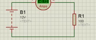
And we'll start by measuring the current. The device used for these purposes is called an ammeter and it is connected in series to the circuit. Let's look at a small example:
As you can see, here the power supply is connected directly to the resistor. In addition, the circuit contains an ammeter connected in series with a resistor. According to Ohm's law, the current strength in this circuit should be equal to:
I = \frac{U}{R} = \frac{12}{100} = 0.12
We obtained a value equal to 0.12 A, which exactly coincides with the practical result shown by the ammeter in the circuit
An important parameter of this device is its internal resistance r_A
Why is this so important? See for yourself - in the absence of an ammeter, the current is determined according to Ohm's law, as we calculated a little higher. But if there is an ammeter in the circuit, the current will change because the resistance will change, and we will get the following value:
I = \frac{U}{R_1+r_A}
If the ammeter were absolutely ideal and its resistance was zero, then it would not have any effect on the operation of the electrical circuit whose parameters need to be measured, but in practice this is not entirely true, and the resistance of the device is not equal to 0. Of course, the resistance of the ammeter is sufficient is small (since manufacturers strive to reduce it as much as possible), so in many examples and tasks it is neglected, but do not forget that it still exists and is non-zero.
When talking about measuring current, it is impossible not to mention a method that allows you to expand the limits within which the ammeter can operate. This method involves connecting a shunt (resistor) having a certain resistance in parallel to the ammeter:
R = \frac{r_A}{n\medspace-\medspace 1}
In this formula, n is the shunt coefficient - a number that shows how many times the limits within which the ammeter can make its measurements will be increased. Perhaps all this may not seem entirely clear and logical, so now we will look at a practical example that will help you understand everything.
Let the maximum value that the ammeter can measure be 1 A. And the circuit in which we need to determine the current strength has the following form:
The difference from the previous circuit is that the voltage of the power source in this circuit is 100 times greater, and accordingly, the current in the circuit will become greater and will be equal to 12 A. Due to the limitation on the maximum value of the measured current, we will not be able to directly use our ammeter . So, for such tasks you need to use an additional shunt:
In this problem, we need to measure the current I. We assume that its value will exceed the maximum permissible value for the ammeter used, so we add another element to the circuit that will act as a shunt. Let us want to increase the measurement limits of the ammeter by 25 times, this means that the device will show a value that is 25 times less than the value of the measured current. All we have to do is multiply the readings of the device by the number we know and we will get the value we need. To implement our idea, we must place a shunt parallel to the ammeter, and its resistance must be equal to the value that we determine using the formula:
R = \frac{r_A}{n\medspace-\medspace 1}
In this case, n = 25, but we will carry out all the calculations in a general form to show that the values can be absolutely any, the shunting principle will work the same.
So, since the voltages across the shunt and the ammeter are equal, we can write the first equation:
I_A\medspace r_A = I_R\medspace R
Let us express the shunt current in terms of the ammeter current:
I_R = I_A\medspace \frac{r_A}{R}
The measured current is:
I = I_R + I_A
Let us substitute the previous expression for the shunt current into this equation:
I = I_A + I_A\medspace \frac{r_A}{R}
But we also know the resistance of the shunt (R = \frac{r_A}{n\medspace-\medspace 1}). As a result we get:
I = I_A\medspace (1 + \frac{r_A\medspace (n\medspace-\medspace 1)}{r_A}\enspace) = I_A\medspace n
So we got what we wanted. The value that the ammeter will show in this circuit will be n times less than the current strength, the value of which we need to measure
Everything is clear with measuring the current in the circuit, let's move on to the next question, namely determining the voltage.
FakeHeader
Connection diagram for voltmeter-ammeter dsn-vc288
The remaining red contact will be connected to the electrical load. Therefore, before the Muse leaves, I’ll give you more details.
To implement smooth adjustment of the output voltage, radio amateurs eliminate resistor R2, and change the tuning resistor R1 to variable. Load tests.
The device has two calibration resistors: voltage adjustment, current adjustment. I turn on the tester at maximum sensitivity.
Its price fluctuates around 4 USD. On a small wire. It will be enough to connect the charger, where the voltammeter is installed, to the battery, and we will see what voltage is currently on it. I re-read the article again and applied the advice on compensating for zero by shorting two contacts on the board. I have a 12 volt, unregulated source left over from Asus ee and a pulsed Chinese step-down module. Meter Voltmeter + ammeter connection diagram
V-meter modification scheme
How to connect a 380v to 220v electric motor
This is how this scheme for connecting additional electronic components with those already existing in the voltmeter circuit was born. The standard resistor of the circuit marked in blue must be removed. I’ll say right away that I found differences from other circuits given on the Internet, for example, the connection of a tuning resistor. I didn’t redraw the entire voltmeter circuit (I’m not going to repeat it), I only drew the part that was necessary for modification. I think it’s obvious that the voltmeter’s power supply needs to be separate; after all, the starting point in the readings should start from zero. Later it turned out that power from a battery or accumulator will not work, because the current consumption of the voltmeter at a voltage of 5 volts is 30 mA.
After assembling the voltmeter, I got down to the essence of the action. I won’t split hairs, I’ll just show and tell you what to connect with what to make it work.
Principle of operation
How to connect a temperature sensor to Arduino
The first device was invented by Schweiger at the beginning of the 19th century, but it was then called a galvanometer. A drawing of a simple ammeter looks like this. On the axis of the bracket there is a steel anchor with an arrow. This structure is located parallel to a permanent magnet, which acts on the armature and gives it magnetic properties.
Lines of force run along the magnet and the arrow, which corresponds to the zero position on the scale. As soon as electric current begins to flow through the bus, a magnetic flux will be formed. Its field lines will be located perpendicular to the lines of the permanent magnet.
The simplest option
Those who don’t want to bother with cutting plastic in the interior, wiring and other joys associated with a voltmeter can take the path of least effort. We are talking about exactly the same devices that work through the cigarette lighter. Yes, they have an error of about 0.1-0.2 V, but this is not so critical, and in the most famous Chinese store, you won’t have to pay more than 400 rubles.
Most of these options come with a built-in thermometer (takes data from inside the cabin), but this additional function is useless (you may not agree with us). However, if you search, you can find options where, in addition to voltage and temperature (or without it at all), there are 1-2 USB ports. But this is really convenient.
PS Options that work from the cigarette lighter are convenient because you will receive information when you really need it, and not always with the turn of the ignition key.
BY42A connection diagram
How to connect a voltammeter to a charger - a selection of diagrams
It will be difficult not to notice their signals, which is a big plus for the manufacturer.
Connection diagram for a voltmeter and ammeter with a separate shunt to the power supply. The shunt is always connected in parallel with the ammeter. Since this information is not available on the seller’s page, I had to scour the web and sketch out a couple of diagrams. Almost all of them are small-sized and can be installed in small power supply cases. The supply voltage has a very wide range, you can supply from 4 to 30 Volts, the red wire is positive, the black wire is negative. This figure shows a wiring diagram for a voltmeter and an ammeter with a built-in current measuring shunt. It is also desirable that the device have a shunt to finalize the connection process. If the connection is incorrect, the device display will show zero values.
By the way, it also overestimates the voltage readings by 0.3 volts. To connect the voltmeter you need to deal with the wires, there are five of them: Three thin ones. The display is two-color red and blue. DIY mini laboratory power supply
How to connect a digital voltmeter and ammeter (Chinese module) to the power supply with your own hands.
Topic: how to install a current and voltage meter on a power source.
It is quite convenient when the power supply has an indicator showing constant voltage and current. When powering a load, you can always see the voltage drop and the amount of current consumed. But not all power supplies are equipped with ammeters and voltmeters. Purchased, more expensive power supplies have them, but cheap models do not. And they are not always installed in homemade power supplies. Today it is possible to purchase for little money a digital module measuring a constant current and voltage indicator (Chinese voltmeter ammeter). This module costs around 3 bucks. You can buy it by parcel from China, at the nearest radio market, electronic components store.
This Chinese digital voltmeter, ammeter module itself measures direct current (up to 10, 20 amperes, depending on the model) and voltage (up to 100, 200 volts). It has small, compact dimensions. It can easily be mounted in any suitable housing (you need to cut the appropriate hole and just insert it there). On the back of the board there are two trimming resistors that can be used to correct the readings of the measured values of current and voltage. The accuracy of this digital Chinese voltmeter and ammeter module is quite high - 99%. The screen has a three-character display in red (for voltage) and blue (for current). This unit is powered by DC voltage from 4 to 28 volts. Consumes little current.
The installation itself, the electrical connection to the power supply circuit, is quite simple. The current and voltage measuring module has the following wires: three thin wires (black minus and red plus for powering the module, yellow for measuring DC voltage relative to any black), two thick wires (black minus and red plus for measuring DC current).
This Chinese ammeter and voltmeter module can be powered either from the source itself, on which we measure electrical quantities, or from an independent power supply. So, after mounting it into the meter body, we solder together two black wires (thin and thick), this will be a common minus, which we solder to the minus of the power supply. We solder together thin red and yellow wires and connect them to the output (plus) of the power source. We connect the electrical load itself to the thick red wire, relative to the soldered black wires (these will be the output wires of the power supply).
It is important to note that the polarity of the current leads is important for correct DC current measurements. That is, it is the thick red wire that should be the output of the power supply
Otherwise, this digital ammeter will show zeros on its display. On a regular power supply (without voltage regulation function), the indicator can only monitor the voltage drop. But on an regulated power source it will be clearly visible what voltage you currently have when you set it.
Video on this topic:
PS In general, connecting this digital Chinese voltmeter and ammeter module should not be difficult. The next time you use it, you will appreciate its performance and you will like it. The three-character measuring unit is considered the most popular, although the four-character one, whose measurement accuracy is no longer 99%, but 99.9%, will be a little more expensive. These digital modules that measure direct current and voltage are also of a separate type, that is, one such unit is either an ammeter or a voltmeter. They have a bigger screen.
Main characteristics of the device
Knowing its structure and operating principles will help you connect the voltmeter correctly.
The type of ordinary portable voltmeter is known to everyone. This is a rectangular box with a front screen, levers, buttons and connectors for contacts. It is equipped with a handle on which it can be placed in a raised position, and it also serves to carry it. There are also very compact options that look like an ammeter. It's just a small box with terminals and a scale with an arrow.
Some devices similar to an ammeter can be identified by the V sign on the display. In diagrams it is depicted with the same letter, but in a circle. Just like the first one, it has a “+” sign at one end. It must be connected to the positive end of the source, that is, to the point with the positive value of the circuit. Otherwise, the pointer will point in the opposite direction to the correct direction.
The greater the resistance inside the device, the better, since in this case the resistance has the least influence on the object being measured, so its readings are more accurate and the range of application is wider.
There are quite a varied number of modifications:
- according to the principle of operation (electromechanical, static, electronic);
- by purpose (pulse, direct/alternating current, phase-sensitive, selective, universal);
- stationary, panel, portable.
A more technical definition of a voltmeter is: a galvanometer with high sensitivity, significant resistance, equipped with a display that displays the potential difference, or electrical excitation value in volts.
Differences between ammeters of various designs
Magnetoelectric system
Unlike the previous device, the AC ammeter is based on an electromagnetic system. Most often such devices are used in networks at 50-60 Hertz. The ammeter device assumes the presence of one or two cores connected to a pointer mechanism. The advantage of the design is its versatility, which allows you to measure direct current in addition to alternating current. The resistance of an electromagnetic type ammeter is higher than that of other models, which negatively affects the accuracy of the result. The scale is nonlinear, so it is difficult to read the ammeter readings. In some cases, a dot is placed in the first half of the scale, indicating that it is impossible to measure current in a given range while maintaining the normal error.
Electromagnetic meter
To reduce the impact of external magnetic fields, ferrodynamic type ammeters are used. The device is characterized by high measurement accuracy. This allows you to avoid installing additional protective screens in the device. The design is based on a closed ferrimagnetic wire. The ammeter needle shows the measured value on a nonlinear scale. Ammeter readings can be taken with the required accuracy not over the entire measurement range, but only starting from the value indicated by the dot.
Ferrodynamic high-precision device
Digital ammeter
A digital current meter is the most convenient to use, as it immediately shows the required value without the need to obtain data using the ammeter needles. It is often included in a multimeter or electronic voltammeter. The most modern instruments have the ability to automatically select the measurement limit. The device is not sensitive to horizontal or vertical position. The accuracy of measurements depends on the sampling and the algorithm used to take readings.
Multimeter with digital ammeter function
Types of ammeters
According to their action, all ammeters are divided into electromagnetic, magnetoelectric, thermal, electrodynamic, detector, induction, photo- and thermoelectric. All of them are designed to measure the strength of direct or alternating current. Among them, the most sensitive and accurate are electrodynamic and magnetoelectric ammeters.
During operation of a magnetoelectric ammeter, a torque is created through the interaction between the field in a permanent magnet and the current passing through the frame winding. The arrow moving along the scale is connected to this frame. The arrow is rotated by an angle proportional to the current strength.
What is an ammeter, its types
As shown in the figure, the device is connected in series to a circuit through which electric current flows. To minimize the impact on real physical processes, it is necessary to reduce the internal resistance of the ammeter. A large scale is useful for taking readings. When selecting suitable equipment, the following factors are also taken into account:
- digital indicator simplifies the measurement process;
- it is easier to work with low and high currents using division into several ranges;
- under unfavorable external conditions (humidity, vibration), the appropriate protection of the device should be taken into account.
Magnetoelectric
The measuring unit of devices in this category consists of two main components. An induction coil is placed between the poles of a permanent magnet. When current passes through the windings, it turns. By attaching the arrow and scale, these movements are recorded to obtain measurement results. Built-in springs limit the amplitude of deviations and return moving components to their original position. The built-in leash regulates the tension. Weights compensate for the force of gravity.
In two diagrams, the number 1 indicates the source of the field, which rotates the coil (3), rigidly mounted on the central axis. The device begins to function when current flows through the circuit. The spiral spring (4) corrects the movements. In the first option, a limiter (2) is installed to prevent damage to the arrow.
The advantages of such an engineering solution are:
- high accuracy;
- good sensitivity;
- lack of additional power sources;
- democratic price.
On a note. The main drawback is the mechanical parts. The complexity of the design implies deterioration in reliability. You should remember the negative impact of shocks and other external influences. This device is suitable for measuring direct current.
Electromagnetic
It is unlikely that an ordinary user will have to repair complex devices. Therefore, the selection and connection of an ammeter is discussed in detail below. Electromagnetic devices are universal. They are suitable for measuring direct and alternating current. The sensitivity in this case is slightly lower compared to the previous example. However, in some situations it is quite sufficient.
Thermoelectric
Devices in this category perform measurements using an indirect method. A thermocouple or similar device converts alternating current into direct current. Its value is controlled by including a magnetoelectric or other ammeter in an additional circuit. The contact version provides increased sensitivity. To exclude galvanic coupling, the sensor is placed in a layer of neutral material (glass, polymer).
Electrodynamic
In this option, two coils are installed side by side. A current is passed through one, connected to the indicator device. The second one is fixed motionless. This scheme is characterized by increased sensitivity. Even weak magnetic fields have quite strong effects on a moving element. To obtain accurate measurements, remove the device as far as possible from sources of interference and use shielding.
Ferrodynamic
A special element of the device is a conductor with ferrite properties. High field strength in the working area significantly reduces external parasitic influences. Such devices, even without special shielding, can be connected to a circuit near power lines.
Read also: Drawings of tin products
Sequence for connecting an ammeter with a shunt
Circuits with current transformers are used at power plants. To connect ammeters in low-voltage circuits, amateur electricians, as a rule, use a circuit with shunts.
Connection diagram for an ammeter with a shunt
Sequence of steps for assembling the circuit:
- Many ammeters are equipped with calibrated shunts. It is necessary to know the approximate range of measurement currents. Knowing the current, the appropriate shunt is selected;
- Attach the shunt to the contact terminals of the ammeter;
- De-energize the device designed to control the current;
- Open the power supply circuit and connect it in series with the load (lamp, resistor, etc.) to an ammeter with a shunt element attached to it, taking into account the polarity of the device (for analog devices) and the source;
- Apply voltage and read data;
- Turn off the power source again, disconnect the ammeter and restore the normal circuit;
- The price of one division of the device is determined based on the current value indicated on the shunt.
In a multimeter, the shunts are already built into the device. You just need to set the switch to the desired measurement range. This is done with the power removed.
Important! If an ammeter is connected to the circuit to determine the charging current between the charger and the battery, then the “plus” of the charger is connected to the “plus” of the ammeter, and the “minus” of the ammeter to the “plus” of the battery
How to choose a shunt for an ammeter
To calculate the parameters of the additional circuit, use the formula R w = R in* I in/( I in - I in), where:
- Rsh – shunt resistance;
- Rin – internal resistance of the ammeter (given in the data sheet);
- Ipr – maximum current for which the device is designed;
- Iin – input current (source) before circuit branching.
Join the conversation
And vice versa. When the output voltage is more than 12V, the LCV voltage stabilizer comes into operation and thereby maintains a constant voltage on the fan of no more than 12V. A fuse is required.
If the source of the measured voltage operates in the range 0 -4.5 V or above 30 Volts, then up to 4.5 Volts the amperevoltmeter will not start, and at a voltage of more than 30 Volts it will simply fail, to avoid which you should use the following diagram: About the wires from the kit: - the wires of the three-pin connector are thin and made of 26AWG wire - thicker is not needed here. Article rating: 3 ratings, average: 5.00 out of 5 Loading
We tried to power it from a separate 12-volt linear power supply - the readings of the dial and digital ammeters coincided.
The shunt is soldered at an angle to the connector, which had to be corrected by bending the shunt. When connecting and comparing the readings with the readings of the multimeter, the discrepancies amounted to 0.2 Volts. Step-by-step connection: It is necessary to decide from which power source the device will operate, separate or built-in.
A fuse is required. Apparently, these voltammeters are intended for use in low frequency equipment powered by an industrial AC network. CONNECTING A VOLT AMP METER to a charger. purchasing a wheel motor for a Fat Bike 1500 watt
Determination of electricity losses in 10(6) kV networks
16.1. The initial data for calculating electrical energy losses in a 10(6) kV network are:
total amount of active electricity W
p(kWh) supplied to the distribution network during the billing period;
amount of active W
A(kWh) and reactive
W
р(kVAr∙h) energy supplied to each line with a voltage of 10(6) kV during the billing period;
daily hourly load graphs I
(
t
) (A) on CPU buses for working days of winter maximum and summer minimum loads, selected for control measurements during the calculation period;
information on the duration of line outages during the billing period, hours;
data on the actual amount of electrical energy consumption for the billing period (kWh, %) for its transmission and distribution.
16.2. Calculation of losses of a 10(6) kV electrical network using computer programs is performed for each section of the line extending from the CPU buses to the subscriber. Before introducing loss calculation programs on a computer, the level of electrical energy losses in electrical networks can be determined using the formulas below.
16.3. Electricity losses in each network line are determined by the following formula:
| () |
where ΔW '
A
-
losses of active energy in the active resistance of the line (f-2);
ΔW « _
A - losses of active energy in the active resistance of the line when transmitting reactive power
16.4. Losses of active and reactive electricity in the distribution line for the estimated period of time t
| (2) |
| (3) |
where K
e is the resistance equivalence coefficient of the distribution line;
R
∑,
X
∑
—
active and reactive resistance of the distribution line, Ohm;
t —
billing period (minus the duration of line outage), h;
I
min,
I
max - respectively, the minimum and maximum load values on the head section of the line, taken from the daily load graphs, taken at the winter maximum and summer minimum, falling during the period of control measurements, A;
β is the load curve shape coefficient.
16.5. The resistance equivalence coefficient allows, to simplify the calculation, to replace a branched distribution line with some equivalent resistance through which the current of the head section of the line flows, provided that the power loss for a certain moment remains unchanged.
Equivalence factor K
e is determined according to the graph depending on the ratio
R
g.y
R
∑and the location of the concentration of a powerful load (the rated power of the transformer substation) along the distribution line (
R
g.y is the active resistance of the head section of the distribution line, Ohm)
| (4) |
where r
o — specific calculated active resistance of 1 km of cable (wire) of the head section, Ohm/km;
I
g.u—length of the cable (wire) of the head section from the CPU to the point of connection of the total load, km.
To determine the location of concentrated powerful load along the distribution line, proceed as follows. The number of loads (TL) of the distribution line is divided in half. On both sides of the proposed cross-section, the total installed power of the TP transformers is determined. Depending on which side of the cross-section (at the beginning or end of the line) the total installed power is greater, curves 1 and 2 on the graph are used. If there is a branch, then it is conditionally replaced by the concentrated load and the total installed power at the point of connection of the branch.
1 - powerful load is concentrated at the beginning of the line;
2 - powerful load is concentrated at the end or middle of the line.
Rice. 1. Dependence of the distribution line resistance equivalence coefficient:
When performing calculations on a computer using software, replacing branched lines with an equivalent load is not required; calculation of losses on a computer is performed for each section of the 10(6) kV network.
16.6. The active and inductive resistance of the distribution line is determined by:
| (5) |
where r
oi,
x
oi—conditional active and inductive resistance of 1 km of cable (wire) of one section of
the i
-th section, Ohm∙km;
I
i is the length of
the i
-th section, km;
k
-number of distribution line sections.
16.7. The average load current for each line for the billing period (year) is determined:
| (6) |
where U
cp is the average voltage on the CPU buses for the calculation period.
If you have daily voltage graphs taken on the CPU buses, you can determine the most probable (distribution mode U
(M)) voltage values ().
16.8. The relative value of the average load current for each line is determined:
| (7) |
where I
min,
I
max - minimum and maximum current taken from daily load measurement schedules during the period of control measurements in the billing period.
16.9. From the average graph Δ I
av =
ƒ
(β) from the value Δ
I
av we can find the shape coefficient of the annual load curve β Fig. 2 []
Rice.
2. Dependence of the graph shape coefficient Δ I av =
ƒ (
β )
16.10. To determine power losses for the entire network, power losses are determined for each line and then summed up:
| (8) |
where m -
number of distribution lines.
Relative electricity losses in the 10(6) kV network for the billing period:
| (9) |
Recommended Posts
Here, no matter how you count, according to the formulas, you still have to adjust. This figure shows a wiring diagram for a voltmeter and an ammeter with a built-in current measuring shunt. After such modifications, I assembled a dsn-vc voltammeter. Separately, I would like to explain how to connect ampere volts class=”aligncenter” width=”1600″ height=”1050″[/img] If the source of the measuring voltage operates in the range from 4.5 to 30 Volts, then The connection diagram looks like this: 2. The devices on the board have SMD trimming resistors with the help of which it is possible to correct the readings of the voltmeter and ammeter. Once power is supplied to the circuit, the indicator will light up. When connecting the device to a DC network, the polarity of the connection is shown on the display. Each shunt has a marking indicating what current it is designed for.
To move or completely turn off the point, you need to unsolder the R13 10 kOhm CHIP resistor, which is located next to the transistor, and instead solder a regular 10 kOhm resistor 0. If the source of the measured voltage operates in the range 0 -4.5 V or above 30 Volts, then up to 4 .5 Volts, the ampere-voltmeter will not start, and at a voltage of more than 30 Volts it will simply fail, to avoid which you should use the following diagram: About the wires from the kit: - the wires of the three-pin connector are thin and made of 26AWG wire - thicker ones are not needed here. In this article we will talk about a fairly cheap, but very common Chinese voltammeter marked dsn-vc Correct connection of the voltammeter
Methods for connecting a car ammeter
There are three main options for connecting an ammeter to a car. Each of them has its own technical features, which it is very advisable to know in advance. There are also less popular methods for connecting an ammeter, but they are either too complicated or the result is not worth the effort. The choice of the optimal connection method depends on the device used and the tasks assigned.
Generator-battery
To implement this method, the simplest one-way ammeter with positive polarity is suitable. When using this connection scheme, we are able to control the current that flows from the generator to the battery and to power the on-board computer devices. However, it is impossible to calculate discharge indicators (i.e. when the motor is not running).
The connection occurs according to the following scheme:
Important! The created node must be carefully insulated to prevent a short circuit in the network.
Battery consumers
This connection method is much more complicated than the previous one, but it is more functional and allows you to obtain more information about the current situation. To implement this method, it is desirable to have an ammeter that works in both directions. In this case, the device will allow you to analyze the current consumed by electrical appliances installed in cars. The shunt for this method must also be suitable, that is, intended for installation to the positive terminal. The connection diagram looks like this:
The need to use a two-way ammeter with such a connection scheme is due to the fact that a one-way device will only show the current used by electrical appliances. Two-way models show more complete information about the network. Therefore, the described connection method is the most popular.
Connecting an ammeter to the negative terminal
This connection method is only relevant if the available ammeter is designed to be connected to the negative terminal. In all other situations, it is rational to use one of the methods listed above. This is due to the fact that connecting to the negative terminal hides a number of inconveniences:
If the supply package does not include a breaker, it can be replaced with a ground switch with a separate button. The converter is not always included in the kit, so you will definitely have to buy it in addition. We strongly do not recommend using cheap Chinese analogues, in which case there is a high probability of device failure. It is necessary to have a converter that can accurately withstand the available voltage.
An alternative option for measuring amperes in a car
Let's consider another way to connect an ammeter to a car. It does not require the device to be integrated into the vehicle network, therefore it is simpler. However, the problems that can be solved using this method are very modest. For this you will need a multimeter and current clamps. To measure, for example, leakage current, you need to do the following:
In this mode, the device will show the current consumed by the network when the main consumers are turned off. You can also measure the consumption of some devices, for example, central locking, radio, navigator. You just need to remember that the power of the consumer being measured when using a conventional multimeter should not exceed 100 W, otherwise the device will simply burn out.
Important! While taking current measurements using the described method, you should never try to start the engine. The current that flows through the multimeter when the starter is operating (more than 100 A) will inevitably put on a spectacular show, after which the device may no longer be restored. To measure starter current, only good current clamps can be used.
Source
General information about the device
The laws of electrical circuits are taught in educational institutions. Every teenager knows the nuances about the directional movement of charged particles. It is represented by the movement of electrons through a conductor and is called electricity. If we consider the practical side, any movement of something in nature (air masses, charges, water in a river) can benefit humanity.
Based on this, various devices are created that calculate and measure all kinds of quantities. For example, to have a detailed understanding of the current, it is worth using an ammeter. The device easily determines the number of charged particles that cross the cross section established in the conductor over a certain period (unit) of time, which is the current strength.
AC Electricity Measurement
Any household appliances powered from the mains show the load with which they consume alternating current. When considering issues of energy use, it is worth remembering the concept of power, for which the final payment is made in kilowatts. In this case, the ammeter acts as a device for performing indirect measurements. In this way, the current strength is determined through the standard formula according to Ohm’s law:
P=I*U, where:
- U is voltage;
- I represents the current;
- P indicates the calculated power.
There are cases when information recorded by the electrical panel is lost. To restore the necessary parameters you will need an ammeter. Sometimes, when servicing a large building, it is not possible to control all the devices that record electricity. The problem is solved by connecting an amplified ammeter to the output of the panel and taking the required measurements. Such tasks should only be performed by specially trained people.
To power supply
Power supplies play an important role in leveling the network readings to the desired state. If not operated correctly, they can cause serious damage to expensive equipment by causing overheating. In order to avoid problems during their operation, and especially in cases where the power supply is made manually, it is advisable to use an inexpensive ammeter and voltmeter.
You can order a variety of models from China, but for standard devices operating from a home network, those that measure current from zero to 20 A and voltage up to 220 V are suitable. Almost all of them are small-sized and can be installed in small power supply cases.
Most devices can be adjusted using built-in resistors. In addition, they have high accuracy, almost 99%. The display displays six positions, three each for voltage and current. They can be powered either from a separate or built-in source.
To connect a voltmeter you need to understand the wires, there are five of them:
- Three thin ones. Black minus, red plus, yellow to measure the difference.
- Two fat ones. Red plus, black minus.
The first three cords are most often combined for convenience. The connection can be made through a special socket connector, or using soldering.
- It is necessary to decide from which power source the device will operate, separate or built-in.
- The black wires are connected and soldered to the minus of the power supply. Thus, a general minus is created.
- In the same way, you need to connect the thin red and yellow contacts. They are connected to the power contact.
- The remaining red pin will connect to the electrical load.
If the connection is incorrect, the device display will show zero values. In order for the measurements to be as close as possible to the actual ones, it is necessary to correctly observe the polarity of the supply contacts. Only connecting a thick red wire to the load will give an acceptable result.
The purpose of the ammeter
Even on old Soviet cars, some kind of ammeter was installed, but it was less functional and informative than modern models. Such a device worked only “in one direction” and showed the direction of the current, that is, to or from the battery. In other words, such a device only provided information whether the battery was charging or discharging at a given time.
Modern models, if connected correctly, provide much more useful information to the car enthusiast. This became possible due to the fact that ammeters have become digital; accordingly, they can read not only the direction of electric current, but also other information. They show the load with fairly high accuracy, which significantly increases their functionality.
In general, an ammeter in a car allows you to monitor the following characteristics of the on-board network:
Only the most important ammeter functionality is listed above. Advanced models provide information about several dozen more key characteristics of the car.
Selecting a voltmeter model
Digital voltmeter circuit.
The modern market of devices for cars offers a wide selection of voltmeter models. The most popular types of devices are:
- analog “pointer” voltmeters - installed mainly on domestic cars, connecting to the dashboard instead of a clock;
- digital sensors connected to the cigarette lighter socket;
- digital voltmeters mounted in the dashboard.
The last two types of devices are most often used, as they combine a modern appearance, accurate readings and ease of installation.
The most realistic measurement results are provided by voltmeters connected directly to the dashboard
Although their installation is sometimes fraught with some difficulties, by installing them you can get constant monitoring of the battery condition, which is especially important when there are a large number of connected nodes
To increase the accuracy of the voltmeter, it is recommended to choose those models in which 4 digits are allocated for voltage readings. This way you can take values down to hundredths of a volt.
Device and principle of operation
If we talk about the principle of operation, then all devices of this type that allow various measurements in electrical networks are of 2 types:
- electromechanical type;
- electronic.
The first category is pointer devices. In them, the arrow is attached to a special frame where the cable is wound. Such a coil will be located next to the magnet in those devices that are usually used for DC networks. Or next to another coil - if the device is intended for alternating current.
But if you use a diode bridge for connection, then it will be able to carry out the necessary measurements in the AC network, but with a slight loss of accuracy.
When an electric current passes through the winding, an electromagnetic field appears in it, which interacts with a magnet or another winding, and the frame rotates. The coil where the arrow is located is prevented from rotating by a spring. For this reason, the angle of rotation of the frame will correspond to the current that flows through it and the potential at the terminals.
It can be a piston type, made of a cylinder and piston, or made of an aluminum plate. To increase the accuracy of the readings, the arrow has special counterweights, which reduce the influence of gravity to zero. And the system itself is made of a type of steel such as alloy steel to reduce its wear.
The sensitive element in electronic analogs is an electronic board that transforms the incoming signal into instrument readings. This device can operate either from the voltage that is measured, or from batteries or external power. Electronic voltmeters themselves are divided into 2 categories:
- analog;
- digital.
In devices belonging to the first category, there is a converter of the incoming signal into an angle of arrow rotation, which shows the value of the voltage being tested, which is displayed on the scale. The disadvantage of such devices is the need to recalculate the scale readings if the measuring limit changes.
The digital voltmeter is equipped with an appropriate display, as well as a converter, thanks to which the signal takes on a digital form. If the device is connected to a network where direct current is present, the polarity of the connection can be seen on the display. The distinctive features of such a device will be compactness and accuracy. True, the last point will depend on the model of the built-in controller.
Connecting a digital voltammeter
How to properly connect an electric meter to the wires
There is an interesting digital DC module that combines the functions of a voltmeter and an ammeter in one device. Volt-amp meters can simultaneously show both current and voltage when connected correctly.
An example of such a device is model DSN-VS288, consisting of:
- the measuring device itself;
- 2-wire cable (ammeter input and output);
- 3-wire cable (device power supply and voltage measurement).
Voltammeter DSN-VS288
Measuring range of the ampere-voltmeter:
- from 0 to 100 V voltage,
- from 0 to 10 A current.
Since the supply voltage of the device is 3.5-30 V, its connection circuit differs:
- If it is necessary to connect the device to a circuit whose voltage lies between 3.5 and 30 V, the general power supply is also used for the device. The black wire of the 2-wire cable goes to the negative, the red wire to the load and from the other load terminal to the positive. On a 3-wire cable: yellow and red are connected together at the “plus” of the source, and black remains free;
- If the power supply voltage is greater or less than the power supply range of the device, then a voltammeter must be connected to an individual power supply. A two-wire cable is connected in the same way; for a three-wire cable, red and black go to the “plus” and “minus” of their IP, and yellow goes to the “plus” of the main IP.
Connection diagrams DSN-VS288
Each type of ammeter is connected according to the same principle, but with mandatory consideration of the quantitative value of the measured current and the selection of appropriate devices and devices for this.
Connecting a voltmeter to a circuit: recommendations
The first thing you need to know is that if you connect a device to a circuit in a series manner, it may fail.
Diagram of connecting a voltmeter to a circuit.
The voltmeter is connected in such a way that its powerful resistance does not change the measurement readings. When connected in series, the current power in the circuit will be minimal.
Correctly, the device is connected to the circuit in parallel to its part: this way it does not affect the flow of currents, and therefore a large resistance is required. Do not confuse a voltmeter with an ammeter, which is connected in series, because there should be a minimum resistance in it.
The current that flows through the device is much less than that flowing through the area of the circuit being tested. There are no influencing forces within it. The difference between the ends of the terminals is the same as the voltage, so it measures it.
The device connection looks like this. To measure the voltage that exists between two selected points in an electrical circuit, you simply need to connect it to them so that such a connection is parallel to the power source. The voltmeter has virtually no effect on the current due to its passage through itself, since it is created specifically for this purpose with significant resistance. Therefore it does not cause any loss of energy.
In order to expand the measurement range, an additional resistor is mounted in series with the winding of the device. In this case, only part of the measured current goes to the meter; it is proportional to the resistance of the device. With a known resistor value, the voltage indicator is determined using a voltmeter.
Such a resistor is built inside the device; it is simultaneously used to reduce the influence of ambient temperatures on the voltmeter readings. To do this, it is made of a material with a low temperature coefficient, its resistance is less than that of the coil, and therefore the total resistance of the device is almost independent of temperature.
BY42A connection diagram
How to connect a voltammeter to a charger - a selection of diagrams
It will be difficult not to notice their signals, which is a big plus for the manufacturer. Connection diagram for a voltmeter and ammeter with a separate shunt to the power supply. The shunt is always connected in parallel with the ammeter. Since this information is not available on the seller’s page, I had to scour the web and sketch out a couple of diagrams. Almost all of them are small-sized and can be installed in small power supply cases. The supply voltage has a very wide range, you can supply from 4 to 30 Volts, the red wire is positive, the black wire is negative.
This figure shows a wiring diagram for a voltmeter and an ammeter with a built-in current measuring shunt. It is also desirable that the device have a shunt to finalize the connection process. If the connection is incorrect, the device display will show zero values.
By the way, it also overestimates the voltage readings by 0.3 volts. To connect the voltmeter you need to deal with the wires, there are five of them: Three thin ones. The display is two-color red and blue. DIY mini laboratory power supply
Share on social networks
Features of use and connection diagram of a two-pole circuit breaker
This figure shows a diagram of connecting a voltmeter and ammeter with a separate current-measuring shunt to the power supply.
Parameters not lower than the output power supply: Uin - No spam, only useful ideas!
The power supply of the device must be within 4.V. This was the reason for writing this article, because, most likely, we are not the only ones who are faced with issues of connecting WR to measurement circuits.
The lower limit does not start from 0, and even the upper limit is doubtful; in the datasheet on the HT Holtek it is limited to 24V; I couldn’t find the original datasheet. There are also other modifications of this module on the Internet, but the essence of the modifications does not change - if you come across the wrong module, simply adjust the circuit diagram on the board by removing the indicator or ringing the circuits with a tester and off you go! C2 - presumably 0. The first three cords are most often combined for convenience.
Tags: voltmeter, ammeter
This figure shows a diagram of connecting a voltmeter-ampmeter of the first model to a charger from a computer power supply. Therefore, I decided to write a specially separate article in which I will tell you in detail how and how to connect a Chinese voltmeter-ampmeter to a charger or a homemade regulated power supply. In the same way, you need to connect the thin red and yellow contacts. Power consumption less than 20 mA.
Once power is supplied to the circuit, the indicator will light up. Most models have special resistors on their housing. It was not immediately and at the right time that it became clear that its power input was galvanically connected to the minus input of the shunt. Thick wires: Black minus ammeter, blue ammeter output, red voltmeter input. The conclusion is a quite passable measuring device, it will allow you to roughly understand the passing current and measure the voltage, but only up to 24 volts.
How to connect a voltammeter to a charger - a selection of diagrams
Resolution 0.28 inches. BY42A can also be found in two board versions, but the color marking of the wires remains the same. AliExpress offers a similar meter for STM8S, but if you look at the pinout, it’s not it. Apply the minus of the external source to the common wire of the circuit. This voltmeter and ammeter is also convenient because it is sold in an already calibrated state.
This introduces a noticeable error when the indicator is powered from the same source from which the current is measured; the error is up to an ampere with my 50A shunt! The fact is that if you connect a voltmeter-ampmeter to the regulated output of the power supply, then when the voltage drops below 4. It will be enough to connect the charger, where the voltammeter is installed, to the battery, and we will see what voltage is now on it. Here Aliexpress very often lends a helping hand, promptly supplying Chinese digital measuring instruments. Voltmeter 100V + ammeter 50A connect the shunt digital voltmeter ammeter
How to connect a voltammeter to a charger - a selection of diagrams
We have selected the 4 most common voltammeters that craftsmen use in their devices. The measurement ranges of most devices are 0-100 V, and also have a built-in 10 A shunt. The connection principle is very similar, but has its own nuances.
Measured voltage 0-100 V; current 0-10 A. The power supply of the device should be within 4.5-30 V.
YB27VA connection diagram
The YB27VA voltmeter-ampmeter has similar parameters in terms of the range of current and voltage measurements. The only difference is a different board layout and color coding of the wires.
The approximate price is 3.5-4.5 USD; there are also trimming resistors on the board.
DSN-VC288 connection diagram
Voltmeter-ampmeter DSN-VC288 is also one of the most popular among radio amateurs. Its price fluctuates within 4 USD.
Many who have encountered such devices complain about the poor quality of calibration resistors.
Model DigiTOP
Connection diagram for differential circuit breaker
This digital DC volt-amp meter comes with reference diodes. It has a two-digit counter. The conductivity of the comparator is at around 3.5 microns. The microcontroller is used with a rectifier. Its current sensitivity is quite high. The power source is a regular battery.
Resistors are used in a switched type device. A stabilizer is not provided in this case. There is only one triode installed. The current conversion itself occurs quite quickly. This device is suitable for home use. Filters are provided to increase measurement accuracy.
If we talk about the parameters of the voltmeter-ammeter, it is important to note that the operating voltage is at the level of 12 V. The current consumption in this case is 0.5 A
The minimum resolution of the presented device is 1 mA. The shunt resistance is located at 2 ohms.
The division coefficient of the voltmeter-ammeter is only 0.7. The maximum resolution of this model is 15 mA. The current conversion process itself takes no more than 340 ms. The permissible error of the specified device is at the level of 0.1%. The system can withstand a minimum pressure of 12 kPa.
Why control the charge current in the battery?
The use of a measuring device can be considered using the example of a typical technological operation. A serviced car battery is infected using a special technique. Set and maintain the current value at 10% of the capacity specified in the passport data. This prevents excessive release of explosive gases. The duration of the procedure (24 hours or more) implies the need to supplement the device with automatic shutdown means.
How to connect the TK-1382 ammeter to the charger
Using the information provided, you can independently select a suitable device, perform measurements, and assemble a shunt circuit. At the preliminary preparation stage, the expected operating range and operating conditions should be clarified. When purchasing, it is recommended to study the manufacturer's official instructions.
How to choose a voltmeter
First of all, you need to determine what exactly you need a voltmeter for. If you need it for constant monitoring of the on-board electrical network, then the best choice is a built-in device with a tachometer mode. To periodically check the health of the battery and generator without leaving the car, a voltmeter inserted into the cigarette lighter socket is best suited. If a voltmeter is needed for serious diagnostics and repair of the on-board network, then choose a multimeter that performs a large number of different operations.
Also think in advance which appearance you prefer - rectangular with a digital indicator, or round with an arrow? The rectangular one takes up less space, but information from it is more difficult to perceive, especially on a bright sunny day. It is difficult to find a place on the front panel for a round pointer device, but information from it is perceived much easier and even bright light does not interfere with it. Think about whether you can connect the built-in device yourself, or do you have friends who will not only connect it, but also not ruin anything in the car? If you doubt your abilities or don’t have such a friend, then buy a voltmeter for the cigarette lighter.
If you are not buying a professional meter, but a regular voltmeter or tester, then there is no noticeable difference between Russian, Chinese or any other devices. Therefore, choose either the one that you like in appearance, or the one that suits you in terms of the number of functions or price.