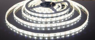
Currently, addressable LED strips (NeoPixel LEDs) based on WS2812 LEDs are widely used in various fields. In this article we will look at connecting such a tape to the Arduino board and learn how to control it in various modes.
Previously on our website, the use of addressable LED strip (NeoPixel LEDs) was considered in the following projects:
- room thermometer on Arduino Nano;
- communication of two Arduino boards over a distance of 3 km using Lora E32.
Why NeoPixel?
The ability to individually control each LED in an addressable LED strip gives you the ability to create unique visual effects for your projects. But remember that if you require very high LED switching speeds, then using such an addressable LED strip is not advisable. Another advantage of the NeoPixel addressable LED strip is its low price compared to other types of addressable LEDs. NeoPixel LEDs are available in ring, strip, rectangle and round shapes - you can choose any type for your projects.
Note : The more NeoPixel LEDs you use, the more RAM and power required to drive them, and the processing time will also increase, so choose the optimal number of NeoPixel LEDs based on the capabilities of the microcontroller you are using.
WS2812B module control timing diagram
While the hardware connections between WS2812B modules are simple - power (5 V and GND) and data (the output of one module goes to the input of the next module), the same cannot be said about the communication protocol. The WS2812B modules use a single-wire interface with the NRZ protocol. A data packet containing RGB values is sent at 800 Kbps.
| Figure 2. | Representation of "0" and "1" in NRZ code for the WS2812B module. |
The packet is transmitted after a reset period (RET or RES) when the data signal is held low for more than 50 µs. As can be seen from Figure 2, both “0” and “1” begin with “log. 1", and the difference between them lies in the relative duration of the states of high (TxH) and low (TxL) levels (Table 1).
| Table 1. | Timing relationships of data signals | ||
| T0H | Code 0, high level duration | 0.35 µs | ±150 ns |
| T1H | Code 1, high duration | 0.9 µs | ±150 ns |
| T0L | Code 0, low level duration | 0.9 µs | ±150 ns |
| T1L | Code 1, low level duration | 0.35 µs | ±150 ns |
| Data transfer time (TxH + TxL = 1.25 µs ± 150 ns) | |||
| RESET | Low Level Duration | More than 50 µs |
Since the color of each RGB LED is specified using 8 bits, 24 bits are required to define the color of each WS2812B module. Figure 3 shows a 24-bit sequence addressed to a single WS2812B module. Data is sent in GRB order, with the least significant bit sent first.
| Figure 3. | 24-bit data packet for the WS2812B module. The least significant green bit (G7) is transmitted first. |
As noted, each WS2812B module requires 24 bits of data. After the first module in the chain receives 24 bits, it will look to see if there is more data at its input. If the flow of data continues, it passes it through itself to the next module in the chain. The modules do this until the data flow stops, after which they use the received values to control the RGB LEDs.
Project diagram
The connection diagram for the WS2812 addressable LED strip to the Arduino board is shown in the following figure.
A resistor in the circuit is necessary to protect the NeoPixel LEDs from damage and for correct data transmission. The best communication distance between the NeoPixel LED module and the microcontroller board is 1 to 2 meters.
Note : if you are using an addressable LED strip with a large number of LEDs, then in this case it is recommended to connect a large capacitor (approximately 1000 µF) in parallel with the + and – of the supply voltage.
Choosing a controller for the address tape
When choosing an SPI controller for smart strips, you need to count not on the backlight power, as is usually done, but on the number of pixels.
These parameters are always indicated on the product body.
As for choosing the power of the power supply, focus on the following indicator. One LED for sw2812b models is approximately 60mA in white light.
Count their total number in the feed, take a reserve of 30% and select a suitable block.
From the power supply, the wires are connected to the controller, and on the other side of the controller the tape itself is powered.
Power can be supplied directly, but a controller is required.
Explanation of Arduino program for working with addressable LED strip
Before you start working with addressable LED strip in Arduino, you need to download and install the library for it - NeoPixel Adafruit library.
Arduino
| 1 | Adafruit_NeoPixel pixels(NUMPIXELS, PIN, NEO_GRB + NEO_KHZ800); |
This function determines the number of LEDs and the Arduino pin to control them.
Arduino
| 1 | pixels.begin(); |
This function initializes the addressable LED strip.
Arduino
| 1 | pixel.setBrightness(b); |
A function that sets the brightness of the LEDs. 1 – minimum brightness, 255 – maximum.
Arduino
| 1 | pixels.setPixelColor(Wich LED,Wich color(Red,Green,Blue)); |
This function sets the LED color using the RGB system by specifying the LED number (from 0 to NUMPIXELS-1).
Arduino
| 1 | pixels.show(); |
A function that activates the specified settings, that is, it turns on the LEDs with the previously specified settings.
Now let's look at sample programs that allow you to implement various options for controlling LEDs in an addressable LED strip.
Specifications
The highest quality and most modern tape is ws2812b.
It differs from its predecessors:
- compactness;
- simple controls;
- unlimited number of LEDs connected in series.
The maximum current supplied to one ws2812b LED is 60 milliamps.
Operating voltage: 5 volts.
Each LED has 256 brightness levels.
Rainbow mode for NeoPixel LEDs
There is an interesting tool on the Internet for conveniently creating various effects for the NeoPixel addressable LED strip - NeoPixel Effects Generator. In it you can set the number of LEDs and the contact of the Arduino board to control them, and after creating the necessary effects for your tape in this generator, you can generate ready-made code for the Arduino board in this generator.
To do this, follow the following sequence of steps.
1. On the generator website, click Add Led Strip.
2. Set the number of LEDs in the strip and the Arduino pin number from which they will be controlled.
3. After that, click on Add Effect and select the desired effect.
4. Set the color of the LEDs.
5. Click on “generate Arduino code” and after that the program code for Arduino will be generated for you, which you can directly paste into the Arduino IDE.
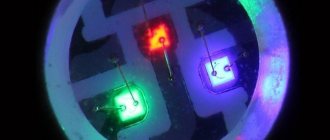
1Description of RGB LEDs WS2812 and WS2812B
The WS2812 LED (or its modification WS2812B, which will be used in this article) is an RGB LED. That is, in one housing there are three LEDs of different colors: red, green and blue.
Appearance and dimensions of WS2812 LEDs
The WS2812 LED has 6 pins, while the WS2812B has only 4.
Pin assignments for the WS2812 LED
| Pin number | Name | Output purpose |
| 1 | Dout | Control signal output |
| 2 | Din | Control signal input |
| 3 | VCC | Control circuit power supply, 6…7 V |
| 4 | NC | Not connected |
| 5 | VDD | LED power supply, 6…7 V |
| 6 | Gnd | Earth |
And here is the pin assignment of the WS2812B LED:
Appearance and dimensions of the WS2812B LEDs.
Purpose of the WS2812B LED pins.
| Pin number | Name | Output purpose |
| 1 | VDD | LED power supply, 3.5…5.3 V |
| 2 | Dout | Control signal output |
| 3 | Gnd | Earth |
| 4 | Din | Control signal input |
The main advantage of these LEDs is that they can be connected in a chain sequentially one after another, they can be connected into strips or assembled into panels. In this case, control is carried out via just one wire. This is possible due to the fact that each LED contains a controller that controls the color and brightness of the three RGB channels. Due to the fact that each WS2812 LED in the chain can be controlled separately, such LEDs are called “addressable”. Today these are the most “advanced” LEDs for organizing large arrays of LEDs.
For example, the diagram shows a series connection of three LEDs. A control signal is supplied to the DIN input of the first LED. The LED processes it and transmits it further from its DOUT output to the input of the next LED in the chain. And so the signal passes through the entire chain of LEDs, each of which reads its own control sequence and changes its color and intensity in accordance with the received command.
Serial connection of WS2812B LEDs
The photo shows a panel measuring 10 by 10 LEDs, which we will experiment with. As you can see, on the bottom of the panel the LEDs are connected in a single chain.
| Top side of WS2812B LED panel | Bottom side of WS2812B LED panel |
Please note that the LED panel is quite power hungry. In the illustration below, this can be seen from the built-in current sensor of the power supply: a panel of one hundred WS2812B LEDs consumes more than 3 amps of current
True, almost all LEDs in this case are turned on at maximum brightness in white (the most energy-consuming mode, since all three RGB channels are used at maximum brightness to ensure white light).
Controlling WS2812B LED panel
The approximate consumption of your device can be estimated as follows. One LED channel at maximum brightness consumes about 20 mA. There are 3 LEDs in one housing. Consequently, one RGB LED consumes up to 60 mA of current at maximum. Multiply this number by the number of LEDs in your matrix or strip - this will be the maximum possible consumption, and your power source must be able to produce this current.
Softbox operating modes
The softbox can perform its immediate duties: provide soft diffused light with adjustable brightness. Two additional controls allow you to change the color tone and saturation. Those. You can shine any color by specifying it in the HSV color model (HSB - Hue, Saturation, Brightness - tone, saturation, brightness). But is this just mode 1 of 7 possible ones? The full list of modes is as follows:
- Static HSB - Hue, Saturation, Brightness
- Dynamic HSB - tone automatically changes from minimum to maximum value
- Rainbow
- Fireflies
- Rainbow noise
- Cloud noise
- Lava noise
All dynamic effects have the ability to adjust brightness, dynamics and scale.
How to solder all components
Test assembly on a breadboard
We will make this homemade project based on the basic project of Alex Gyver and further development of this idea in the form of the GyverPanelWiFi project from vvip-68.
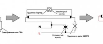
Initially, the developers propose a rather complex scheme:
Circuit using NodeMcu board
However, not every user needs all the capabilities of the project. You can easily remove the speaker (it is used for the alarm clock), the board with a slot for the memory card (it is needed for GIFs and videos), the display for indicating modes and the button for manually switching them.
If we simplify the project, it will be enough to assemble something like this:
Circuit using Wemos D1 mini board
Even from this scheme you can throw out the unit with the memory card and use a standard set of effects.
It turns out that you just need to connect the control board with the diode strip and supply power to both elements. The mode switching button is used optionally here.
You can connect the diode strip into a matrix using any of the methods following the example above. Serial connection (zigzag) does not require soldering at all; pieces of tape are connected to each other by connectors. It will be enough to solder two wires for power supply at the beginning of the tape and a logical contact on the control board.
If the length of the tape turns out to be too long, I recommend that you apply power not at the beginning or end, but to insert the contacts from the power supply into the gap approximately in the middle.
It took me several hours to assemble last year’s matrix, but I assembled the garland from this project in 45 minutes. All thanks to the Chinese, who began producing ready-made tapes with connectors instead of soldered diodes. But the number of “light bulbs” in the garland has increased 10 times!
Don't forget to provide a connector for quickly turning the control unit on and off so that it can be reflashed if necessary.
Why so early
Most of the components of such a garland cannot be found in regular stores. To assemble all the necessary kit, you will need to spend a lot of time and go to several electronics stores or radio markets.
It is best to order everything at once on AliExpress. The components will arrive in time for the New Year holidays and you can easily repeat this project to the envy of all your neighbors.
Last year we already made a similar garland for the window. Personally, this thing made me happy all winter; neighbors and passers-by often stopped in front of the windows to watch the fancy animations and lighting effects.
This time I propose to modernize an already familiar project and assemble a cooler garland. If the previous version consisted of only 100 LEDs, then the new project will contain at least 1000 RGB addressable LEDs! This allows you to display not only more detailed effects, but also demonstrate GIFs, animations and even specially prepared videos.
Essentially, we will turn the windows of an apartment or balcony into a LEG panel with low resolution.