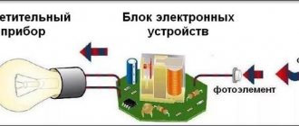
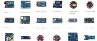
Independent production of various automatic systems has become available thanks to the use of ready-made Arduino boards. Programming such devices does not take much time and requires virtually no special knowledge. The Arduino light sensor is a fairly simple electrical system that can be installed and configured without any help.
This article will discuss the most popular options for using lighting elements of this type.
Sensor characteristics
It is necessary to know in advance about the main parameters of this element so that during installation and operation the basic technical requirements for the safe use of devices of this type are not violated. The sensor board can be made using an analog or digital circuit. In the second case, the device is equipped with a trimming resistor, with which you can change the characteristics of the output signal manually.
Regardless of the type of device, the board is equipped with 3 contacts. Two connecting elements supply power (+5 and GND), the third contact is used to transmit a digital signal (indicated on the board as S or D0).
The light sensor of the Arduino hardware platform is a fairly simple circuit. The main element of such a device is a photoresistor, which changes the resistance of the electrical circuit depending on the illumination.
Infrared LED module KY-005 [4-5]
The module is an infrared LED without any additional elements; there is no additional resistance on the board.
The module has dimensions of 35 x 15 mm and a weight of 1.3 g. As the author understands, connecting this LED is no different from connecting a conventional visible LED. The central contact of the module is not connected to anything, the “-” contact is common, the “S” contact is informational. The author connected a 200 Ohm resistor in series with the LED, and the current consumed by the LED was 17 mA. The emission of this LED cannot be seen by the eye.
Using the camera's matrix, you can register the radiation of the LED; for this, it is advisable to set the sensitivity to at least 800 ISO, turn off the flash, open the camera aperture as much as possible and minimize ambient light.
Principle of operation
In an Arduino system, a sensor of this type will act as a voltage divider. On one arm of such a circuit, the potential difference will directly depend on the lighting level. On the other side, voltage is supplied to the analog input of the device.
The controller chip converts the received analog signal into a digital one. The output voltage coming from the device will be minimal (tends to zero) in normal lighting conditions and will increase significantly in the dark. The light control system is based on this principle.
Comparison of BH1750 and TSL2561
The visible light spectrum ranges from 380 nm (violet) to 780 nm (red) (in a vacuum). In short, the BH1750 simply measures it. The TSL2561, in addition to the visible spectrum, also measures infrared radiation. It has two diodes, one for visible and the other for infrared. In my opinion, the BH1750 meets most requirements, while the TSL2561 offers a wider range, greater sensitivity and greater accuracy.
For comparison, both sensors were placed in parallel in a breadboard, one next to the other. Thus, it is possible to obtain almost identical radiation to both sensors.
More details on how to work with TSL2561 in Arduino can be found in a separate article: Connecting a TSL2561 digital light sensor to Arduino.
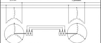
Connection diagram for TSL2561 and BH1750 to Arduino via I2C
The following figure shows the connection diagram of TSL2561 and BH1750 ambient light sensors to Arduino UNO.
Sketch example
#include #include #include BH1750 bh1750; Adafruit_TSL2561_Unified tsl2561 = Adafruit_TSL2561_Unified(TSL2561_ADDR_FLOAT, 12345); void setup() { Serial.begin(9600); Wire.begin(); /* TSL2561 */ if (!tsl2561.begin()) { Serial.print(F("There was a problem detecting TSL2561... check your connection!")); while(1); } tsl2561.setGain(TSL2561_GAIN_1X); tsl2561.setIntegrationTime(TSL2561_INTEGRATIONTIME_402MS); /* BH1750 */ bh1750.begin(BH1750::ONE_TIME_HIGH_RES_MODE); Serial.println(F("BH1750 vs TSL2561")); } void loop() { /* Read readings from TSL2561 */ sensors_event_t event; tsl2561.getEvent(&event); /* Read readings from BH1750 */ float lux = bh1750.readLightLevel(); /* Send the light value to the serial port */ if (event.light) { Serial.print(F("TSL2561: ")); Serial.print(event.light); Serial.println(F("lx")); } else { /* If event.light = 0 lux sensor, probably rich and reliable data could not be generated! */ Serial.println(F("TSL2561 Rich")); } Serial.print(F("BH1750 : ")); Serial.print(lux); Serial.println(F("lx")); delay(1000); }
Result
Based on the results, the TSL2561 and BH1750 give almost identical performance under the same conditions. This suggests that the sensors themselves come calibrated from the factory.
Connection
The light sensor will work correctly in the Arduino system only if it is connected correctly. In order to do this work yourself, you need to prepare:
- Light sensor for the Arduino system.
- Arduino board (Nano, Uno, Mega).
- Any LED suitable for voltage.
- Solderless breadboard.
- Wires for connection.
When everything you need is prepared, you need to connect the 5v output of the Arduino board to the corresponding connector of the device. Then the ground (GND pin) is connected in the same way. The sensor output S is connected to pin2 of the main board.
If the element was connected correctly, then when the illumination changes, the electrical voltage at the S output will vary from 0 to 5 Volts. The digital sensor, in turn, will convert this indicator into a range of values from 0 to 1024, for further output to information display devices.
The LED is connected to pin 13 of the Arduino board, both when using analog and digital devices. If the device design has a trimming resistor, then it can be used to adjust the sensitivity of the working element within a wide range.
IR receiver module KY-022
The infrared radiation receiver module has dimensions of 24 x 15 mm and a weight of 1.6 g and is a printed circuit board on which the receiving module itself and a red LED with additional resistance are located [6-7].
The module has three outputs: the central unmarked one – +5V power supply, the “-” contact – common, the “S” contact – informational. Current consumption: 200 µA in standby mode, 500 µA with LED running.
When an infrared signal is received, the LED on the board blinks, which is quite convenient when debugging designs on a breadboard.
To fully use the IR receiver, you can use the IRremote library [8-10]. For an example illustrating the operation of this device, you can use the IR program. You can use the TV remote control as a signal source.
TV remote control codes
Similarly, the module can receive signals from a remote control for an LED lamp.
Using this sensor, it is not difficult to organize multi-command remote control within line of sight, with a distance between the receiver and transmitter of about 3-5 m.
Sketch for an analog type sensor
To transmit a signal, the device must be programmed correctly. For an analog sensor, the digital code will be as follows:
You can download the text of the sketch here: here
This code outputs digital data from the sensor to the monitor. The first block is responsible for the correct connection to the monitor port. Then the data received from the device is displayed on the display.
IR rangefinder module KY-032
The module is designed to detect obstacles without direct contact with them. An IR LED and an IR photodetector are located on the module’s printed circuit board; when the intensity of radiation reflected from an obstacle exceeds a specified threshold, a sensor response signal is generated.
The module has dimensions of 45 x 16 x 12 mm, weight 4 g, and a mounting hole with a diameter of 3 mm is provided in the module's printed circuit board. The board has a four-pin connector through which the module is powered and information is transferred. The purpose of the connector pins is as follows: “GND” – common wire, “+” – +5V power supply, “OUT” – information output, “EN” – operating mode control. The “Pled” LED is used to indicate the power supply to the sensor; when triggered, the “Sled” LED lights up.
A low logic level appears at the information digital output “OUT” if there is an obstacle in the field of view of the sensor, otherwise a high logic level appears at the output. You can verify this by loading the AnalogInput2 program into the Arduino UNO memory, then when the sensor is triggered, the following picture will be observed in the serial port monitor of the Arduino IDE program.
According to sellers [21-22], the sensor can detect obstacles at a distance of 2 to 40 cm. The author of this review managed to achieve the sensor triggering at a distance of 5.5-3.5 cm from a white obstacle (sheet of paper). The sensor does not see a black rough surface (CD box) at all; the sensor registers a distance of about 2 cm on a black glossy surface.
According to the documentation, to adjust the modulation frequency of IR pulses to a frequency of 38 kHz, use a trimming resistor marked 103, and to adjust the sensitivity of the sensor, use a trimming resistor marked 507. As can be clearly seen in the previous photographs on the board that the author received, both variable resistors are marked 103. Perhaps This is a defect in this particular device. This may explain the short range of the sensor.
The sensor consumes a current of 4-5 mA in operating mode and 5-6 mA when triggered. If you set the sensor to the minimum sensing distance, you can slightly reduce the current consumption (by about 1 mA). In this photo, you can also see that when the sensor was triggered, the “Sled” LED lit up.
According to the description of this sensor, the “EN” pin is used to control the operating mode when the jumper is removed. When the logical level at the “EN” input is low, the sensor is turned on; when the logical level is high, the rangefinder module is in sleep mode with reduced power consumption.
However, according to the author’s observations, when the jumper was removed, when the “EN” output was not connected to anything, the current consumption increased to 13.5 mA, and the sensor stopped responding to the obstacle. With the jumper in place, applying a low logic level to “EN” (from the “GND” socket of the Arduino UNO board) led to a jump in current consumption to 150 mA. When “EN” is applied to a high logic level (from the 3.3 V socket of the Arduino UNO board) and the jumper is removed, the sensor works as usual. In general, in this mode the sensor behaved somewhat strangely, although this may have been due to errors in the experimental methodology that the author of this review made or due to the defective nature of this instance of the sensor.
Thus, on the one hand, the sensor can be used for its intended purpose, but in fact this sensor is not superior to simpler IR distance sensors [23]
Smooth change in LED brightness
The Arduino board controller can be programmed so that when the light changes, the brightness of the LED changes. Changing this parameter will be done using PWM. For this purpose, analogWrite() will transfer a value from 0 to 256 to the LED pin. To convert the digital value from the sensor to PWM, the map() function will be used:
You can download the text of the sketch here: here
This will ensure that the backlight is adjusted in a fully automatic mode.
Installing the BH1750 library
The library can be installed from the environment itself as follows:
- Download the BH1750 library from github;
- In the Arduino IDE, open the library manager: Sketch->Connect Library->Add .ZIP Library...
- Select the .ZIP archive and click Open/Open.
- The library is installed.
Pros and cons of the sensor
A significant disadvantage of this type of sensor is the variation in the sensitivity of the element depending on the radiation spectrum. The difference can reach several orders of magnitude. In some cases, the sensor may completely stop responding to changes in light intensity.
Low reaction speed is also a disadvantage of such devices. If the light on the sensing element is not constant (blinking), the sensor may also be unable to respond to rapidly changing conditions.
The main advantages of the sensor are its simplicity of design and reliability of use. The Arduino system, which does not take much time to connect to the sensitive element, is quite resistant to interference, temperature changes and other unfavorable operating conditions. The cost of such an element is also low, which is also an undoubted advantage of such a system.
Physical properties of photoresistors
Photoresistors have all the properties of conventional resistors, including resistance measured in Ohms. A significant difference is the ability to change the resistance in accordance with the intensity of the light flux affecting the sensitive element.
Photoresistors differ in size and technical characteristics, which are quite arbitrary for each of them. Even released in the same batch, they can have different indicators, differing by half or more. Thus, each element is used in individual conditions and a certain level of illumination. They distinguish between light and darkness very well, and nothing more is required from them. In addition, photoresistors are able to recognize the minimum and maximum degree of illumination.
The technical characteristics of these elements are generally the same. The products differ only in size, which for a round shape ranges from 5 to 12 mm in diameter. The resistance varies in the range from 10 kOhm during daylight hours to 200 kOhm at nightfall. Photoresistors have a sensitivity range and are capable of detecting wavelengths from 400 nm violet to 600 nm orange. Any power source with voltage up to 100 volts and current up to 1 mA is suitable for operation.
What photoresistors can be used
If during operation the main sensitive element fails, then it is not necessary to purchase a new sensor. In specialized stores, as well as on online sites that sell parts of this type, you can select a part that is suitable for the main indicators. When selecting a new element, you should be able to correctly read the product labeling. By the photoresistor number, you can determine its resistance values at different light levels, for example, if the datasheet indicates a range of 12–100 kOhm, this means that in the dark the element will have a resistance of 100 kOhm, and in bright light - 12 kOhm.
If necessary, modern elements such as VT83N and similar should be used for replacement. If the documentation for a photoresistor indicates its sensitivity, then you should also understand that the spread in the indicators can be significant. Even by purchasing parts from the same manufacturer, you can get products in which the difference in this parameter can reach 50%.
Photo interrupter KY-010
When designing devices with moving parts, it may be important to count the number of revolutions or whether a part has reached a certain position. This can be done using mechanical limit switches or reed switches, but these elements have mechanical moving parts, which means they will wear out, stick, etc. over time. For similar purposes, you can use the KY-010 optocoupler [11], which has no moving parts and is therefore more reliable.
The photointerrupter module has dimensions of 24 x 15 mm and a weight of 1.2 g
This device is an infrared LED with a current limiting resistor. The LED illuminates the phototransistor, from the collector of which the useful signal is removed. The module has three outputs: the central unmarked one – +5V power supply, the “-” contact – common, the “S” contact – informational. Current consumption 10 mA.
The module works reliably when connected, instead of a tact button with the LED_with_button program [12].
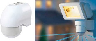
Where is the light sensor used?
After we connect the light control device to the Arduino system, it can be used for practical purposes. This element is ideal for organizing landscape and façade lighting.
The advantage of using automation is that a person does not need to be distracted to turn on the lighting of a building or any other object when necessary. Moreover, the system will also turn off automatically when the light level reaches a certain level. In the latter case, the sensor will also save a considerable amount of electricity. Even when using LED elements that have been in use for a long time, timely shutdown will reduce electricity consumption and also extend the service life of lighting devices.
The Arduino sensor is also ideal for the plant growing business. If the cultivation of light-loving vegetables is carried out in a greenhouse, then timely switching on the lighting will increase the yield and presentation of the products.
Pulse sensor module KY-039
This module is a printed circuit board on which an infrared photodiode and a phototransistor are located. Theoretically, based on changes in the transparency of the fingertip, this module should allow one to determine the pulse rate [13-14].
The overall dimensions of the module are 24 x 15 x 15 mm, weight 1.4 g. The module has three contacts: central unmarked - +5V power supply, contact “-” - common, contact “S” - information. Current consumption 10 mA.
As the author understands, the LED should be directed to the phototransistor
Apparently, it is not easy to achieve adequate performance from this module [15].
However, as an optocoupler it works well. If you load the AnalogInput2 program into the microcontroller’s memory, you can observe that the module reliably responds to the intersection of an infrared beam. However, the author did not register any noticeable fluctuations in readings that could be associated with the pulse. In principle, the readings change in the same way, regardless of what blocks the field of view of the phototransistor: a fingertip, an earlobe, a sheet of paper, a ruler.
It was also not possible to achieve functionality with the demo code [16]. Thus, it turns out that this module is a regular optocoupler, although, of course, the author may be wrong.
How to connect BH1750 light sensor to Arduino
This time we will connect the digital 16-bit light sensor BH1750 (lux meter), implemented on the GY-302 module, to the Arduino.
We will need:
- Arduino UNO or other compatible board;
- module GY-302 with digital light sensor BH1750;
- connecting wires (here is a good set);
- personal computer with Arduino IDE development environment.
1 Connection diagram of the BH1750 sensor to Arduino
Let's consider the GY-302 module with the BH1750 sensor. The BH1750 sensor is a digital 16-bit digital light sensor, which sets its measurement range from 1 to 65535 lux.