The implementation of the technological process involves the use of various equipment. In some cases, it is necessary to achieve synchronous and in-phase rotation of the axes of various devices. Sometimes, for some reason, a mechanical connection is not possible. Then, instead of a clutch, a synchronizer is used - a special sensor, thanks to which the required synchronization can be achieved. It is often part of special systems that need to be rotated at a certain angle at a distance. Selsyn operates in receiver and transmitter mode. It is worth understanding in detail what it is, how it works and where it can be used.
Types of synchronous communication
Before you begin to understand what selsyns are and how they function, it is worth getting acquainted with the existing types of synchronous communication. According to this parameter, systems are usually divided into asynchronous rotation and rotation systems. Each variety has its own characteristics.
Synchronized rotation
It consists of two identical asynchronous electric motors equipped with phase-wound rotors. The rotor windings are connected. The stator is connected to 380 V.
Synchronized rotation
The composition includes selsyns, the execution of which allows self-synchronization. Depending on the number of phases they are divided into:
- Three-phase, whose design is fully consistent with asynchronous motors. The scope of use of such devices is limited due to the presence of a difference between the synchronization moments when the rotor rotates;
- Single-phase, similar in design to synchronous machines with minimal power. The field winding of such equipment only works when passing alternating current.
Watch the video at the end to understand the features of such a system.
Operating principle of various schemes
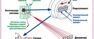
The principle of operation of the system is clearly visible in the diagrams presented in the figure. In diagram “a”, the sensor and receiver are connected through single-coil stator windings to a single AC network, and the rotor windings with three coils are connected to each other. The result is a “sensor-receiver” system. When the rotor of the selsyn sensor is rotated by any angle, the rotor of the receiver will rotate by exactly the same angle.
The basis of synchronous communication is electromagnetic induction. Under the influence of alternating current in the stator winding, currents are induced in the rotor winding, the magnitude of which is influenced by the location of the stator and rotor windings relative to each other.
When the rotors in both selsyn devices are located identically relative to the stators, the currents in the wires connecting the rotors will be generally equal and opposite to each other. Therefore, the current in each coil will be zero. Consequently, the selsyn shafts are at rest and their torque is also zero.
When the rotor of the selsyn sensor is rotated at some angle, this balance of currents is disrupted and a torque appears on the receiver shaft. Its rotor will rotate until the current imbalance completely disappears. This imbalance will disappear when the rotor of the selsyn receiver takes the same position as the rotor of the sensor.
In automatic control mode, the receiver is often required to operate in transformer mode. Diagram “b” shows that the receiver rotor is fixed motionless, and the stator winding is disconnected from the network. Next, an EMF will be induced in it under the influence of the current flowing through the rotor windings. The magnitude of this current will depend on the position of the sensor rotor. That is, the magnitude of the EMF of the receiver rotor will be in proportion to the angle of rotation of the selsyn sensor. In the initial position, both rotors are shifted by 90 degrees to each other, so the emf on the sensor rotor will be zero. Thus, rotation of the sensor rotor will cause an induction of EMF on the receiver rotor, proportional to the mismatch angle of both rotors.
Synchronized turning systems: basic modes
Selsyns operate in two modes. Each of them has its own characteristics that must be taken into account when choosing equipment.
Indicator
If the equipment operates in this mode, it means that the rotor of the receiving device is connected to the driven axis. The diagram is relevant when choosing the minimum braking torque for the driven axle and placing an indicator arrow on it. The field windings are connected to a common circuit. Synchronizing devices are combined with a communication line.
The generated magnetic fluxes initiate the occurrence of EMF on the windings of all phases. A slight mismatch leads to the flow of electric current. Due to the flow, multidirectional moments are formed in the sensors and the receiving element of the synchronizer. With their help, it is possible to completely level out the mismatch angle.
The rotor located on the sensor is braked. As a result, the synchronization torque affects the mechanism that turns the drive axle. Thanks to this design, it is possible to ensure simultaneous rotation of the rotors of both connected elements to the same angle.
Transformer
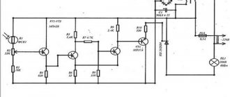
The electrical signal that appears when the rotors are mismatched first goes to the amplifying part of the circuit. Next - onto the rotor of the actuator. The latter begins to turn the rotor of the receiving element and the driven axis until the existing difference is completely leveled. This mode is relevant when applying a braking torque of a sufficiently large value to the driven axis. That is, it helps to turn the mechanism.
The sensor winding is connected to the drive axle and connected to a 220 V power supply. An amplifier is used to supply voltage to the element that controls the engine control. The receiver winding is used to connect the synchronizer. A communication line is used to combine the synchronization windings of two synchronizers. A current is induced in the exciting winding, which creates an EMF in the synchronizing winding.
Current flows through both elements as their windings are connected. Magnetic pulses are formed in the receiving element. If the elements are mismatched, an emf appears in the winding under the influence of the flux. A voltage appears at the input, triggering a special amplifying element. From it, voltage is supplied to the stator, which belongs to the actuator. This leads to the fact that the driven axle begins to turn behind the receiver rotor. As the existing difference is eliminated, the voltage becomes zero and the rotation of the driven axis stops.
Features of the technology used and the design affect the magnitude of the error. These include:
- The difference between the parameters of the sensor and the receiving device;
- Uneven magnetic conductivity indicators;
- Lack of symmetry in the windings.
When transmitting an angle, errors inevitably occur. Their appearance is due to certain operating conditions. When the resistance value in the control network changes, the operating order of the synchronizers will change.
General information, classification
Synchronous communication machines are designed for synchronous or in-phase rotation of two axes that are not mechanically connected to each other, or for their rotation. Induction synchronous communication systems are divided into three-phase and single-phase. Three-phase systems are used to synchronize two drive motor shafts that are not mechanically coupled. Typically these are relatively high power power systems called electric shaft systems. They are used, for example, in mechanisms for raising bridges, sluice gates, in paper industry installations, etc. Single-phase systems are used in low-power installations and are widely used in automatic device circuits. Micromachines used in inductive synchronous communication systems as sensors and receivers are called selsyns, emphasizing their ability to self-synchronize (self synchron means self-synchronizing). In the theory of synchronous communication of automatic devices, two concepts are distinguished: synchronous indicator transmission - indicator mode of synchronizers and servo drive - transformer mode of synchronizers. In the first case, it is necessary to transmit only a minor moment, necessary, for example, to turn the arrow of a device (indicator) to indicate at a distance the position of any regulatory body - valve, valve, damper, valve, etc. Transmitting readings to the control panel is especially important in cases where for some reason a person cannot approach the regulated body. The synchronous indicator transmission diagram is shown in Figure 347. Here, the synchronous indicator sensor D (driver) and the selsyn receiver P (working device) at the drive angle a work out the proportional angle ca directly, that is, the indicator arrow is on the axis of the receiver P. If necessary, transmit The angle of rotation of the mechanism, to the shaft of which a more or less significant moment of resistance is applied, the indicator circuit can be used only with powerful power synchronizers. The communication line must also be powerful. It is more rational and simpler to do otherwise: transmit a weak signal from the sensor to the receiver, which then, being amplified, affects the actuator connected to the drive mechanism. In such a servo drive system, the communication circuit is designed so that the receiver voltage P (signal) is a function of the angle of rotation of the sensor rotor D. In addition, there must be feedback between the receiver and the actuator motor, bringing the rotors of the sensor and receiver to a consistent position (zero signal position ) upon completion of testing. The servo drive diagram is shown in Figure 348. On the winding device D, excited by the mains voltage, a mechanical rotation is carried out through an angle a (winding angle). The signal generated in the processing device I, after preliminary amplification in the amplifying device CU in the form of a control voltage, is supplied to the executive motor ID, excited by the mains voltage. The actuator motor, being mechanically connected to the load shaft, causes it to rotate.
Rice. 347. Scheme of synchronous indicator transmission. Rice. 348. Servo drive diagram.
Thanks to the mechanical feedback of the actuator motor with the operating device P, the control voltage will gradually decrease, and when the operating device P rotates through the winding angle a, Uy will become equal to zero and the executive motor will stop. As a result, the load shaft will rotate by an angle a or proportional to it sa. Inductive synchronous communication systems have a number of positive properties: the absence of spark switching, that is, breaks in the power supply circuit of the sensors during system operation; high accuracy, ensuring small error angles between the positions of the sensor and receiver rotors in a coordinated mode (not higher than 2.5° for low-class machines); smooth processing of sensor rotation by the receiver; the ability to have a contactless sensor and receiver; same type of sensor and receiver.
Design
The execution of selsyns dictates their operating principle. It is customary to highlight:
- contact ones, in which brushes and slip rings are used to connect the rotor winding and the external circuit;
- non-contact, which do not contain contact elements.
Each variety has its own distinctive features, which you should definitely familiarize yourself with in order to understand the principle of operation.
Contact
Contact motors are similar in design to asynchronous electric motors with a wound rotor and low power. They consist of a non-salient pole rotor and stator. Thanks to this, both windings are distributed. The rotor has an excitation winding. Two rings are used to supply electric current.
Some models already have a stator and rotor. This is their clear advantage. As a result, the synchronization torque increases. However, the contact elements in this case are a clear disadvantage.
Contactless
No contact elements are needed to turn them on. Both windings are initially installed on the stator. The rotor has a characteristic cylindrical shape. For its manufacture, materials with ferrimagnetic properties are used. An aluminum layer divides the rotor into two poles.
Toroidal cores are located at the ends of the selsyns. Their internal part is located above the rotor. The outer one is connected to the rods of the external magnetic circuit. Electrical steel sheets are used for the manufacture of cores. The single-phase winding of the device consists of two disk coils located on both sides of the stator between the cores and the synchronization winding.
During operation of the device, a pulse-type magnetic flux is closed. The three-phase synchronizing winding is connected at the stator. The position of the magnetic induction flux axis changes as the spatial position of the rotor changes. It occupies a different position relative to the synchronizing windings. The magnitude of the resulting EMF directly depends on the angle through which the rotor was able to rotate.
The disadvantage of such devices is the less efficient use of active materials. In addition, they are on average 50% heavier than their contact counterparts, due to large air gaps. Thanks to the latter, the magnitude of magnetizing currents increases.
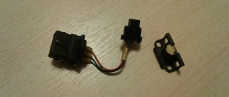
Selsyn receiver
The selsyn receiver differs from the selsyn sensor by the presence of a damper.
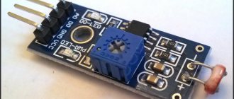
| Depth indicator. |
The selsyn receiver is installed in the control panel and, through gears, rotates the depth indicator and the tachogenerator of the speed indicator. An alternating current of 10 V is supplied to one winding of the tachogenerator; the generated voltage is removed from the other winding, the value of which is proportional to the rotation speed of the measuring roller. The generated voltage is fed to a voltmeter, the scale of which is calibrated for reading.
The selsyn receiver in this circuit operates in transformer mode; its rotor remains motionless. The mismatch that occurs when the rotor of the selsyn sensor is rotated causes a voltage in the excitation winding of the selsyn receiver - a mismatch signal.
Selsyn-receiver - reproduces the law of motion specified by the selsyn-sensor in the form of angular movement of the rotor, proportional to the angular movement of the rotor of the selsyn-sensor.
| Scheme of remote induction transmission using selsyns. |
The selsyn receiver has the same circuit as the selsyn sensor. Its stator is powered from the same alternating current network, and the phase windings of the rotor are connected through a three-wire communication line with the phase windings of the rotor of the synchronizer sensor.
The selsyn receiver 4 is connected to the selsyn sensor via an indicator circuit.
The selsyn receiver differs from the selsyn sensor by the presence of a damper.
A selsyn receiver with a rotor that rotates freely under the influence of a weak torque, used only to drive a pointer or indication mechanism.
The selsyn-receiver rotates to the angle specified by the primary converter not independently, but with the help of an auxiliary motor, the control winding of which is supplied with the output voltage of the selsyn-receiver through an amplifier. Here, the matched position is the position at which the voltage at the output of the synchronizer-receiver is minimal or equal to zero.
| Copier. |
The selsyn receiver is driven into rotation by the portal movement gearbox. As soon as the selsyn sensor rotates at any angle, voltage appears at its output. This voltage is amplified with the help of an amplification unit and an electric machine amplifier and is supplied to the armature of the electric motor of the portal movement drive. The synchronizer receiver rotates together with the electric motor through a gearbox.
| Synchronizing torque curves of single-phase synchronizers. |
A selsyn receiver with primary and short-circuited calming windings distributed in the rotor slots has a torque curve M / (b) approaching a sinusoid. This allows the use of such synchronizers in systems operating in indicator mode. The purpose of the short-circuited calming winding on the rotor, perpendicular to the primary winding, is to reduce the inductive resistance of the stator winding along the transverse axis compared to the longitudinal axis, since the air gap in this type of synchronizer is uniform. Therefore, the use of a short-circuited winding on the rotor is equivalent to a salient-pole rotor design.
Position sensor function
If you take and in some way (manually, for example) rotate the rotor of one of the devices at a certain angle, the balance of currents in its coil is disturbed. Due to the electrical connection, a similar mismatch of current balance is observed in the coils of the second device. As a result, a resultant appears that is different from zero, which leads to the formation of an e/m field and a moment of induction (rotational force). Under its influence, the movable assembly of the executive part will rotate to a state in which the balance of currents is completely restored. It is easy to understand that this state will correspond to the position of another device.
Types of selsyn sensors
Any operating synchronizer includes such mandatory elements as a stator and a rotor, made in the form of windings with electromagnetic coupling. The following types of electrical devices are known, differing in the number of coils located in the stator and rotor. They can be represented by the following combinations:
In the latter case, the number of windings in both parts is completely the same.
According to their practical application (use in electronic auto-adjustment circuits), these devices are divided into the following types:
- sensor devices;
- synchronizers-receivers;
- differential type devices.
To understand the operation of a classic selsyn device, you will need to consider its schematic representation (photo on the right).
What is a selsyn sensor and why is it needed?
The implementation of the technological process involves the use of various equipment. In some cases, it is necessary to achieve synchronous and in-phase rotation of the axes of various devices. Sometimes, for some reason, a mechanical connection is not possible. Then, instead of a clutch, a synchronizer is used - a special sensor, thanks to which the required synchronization can be achieved. It is often part of special systems that need to be rotated at a certain angle at a distance. Selsyn operates in receiver and transmitter mode. It is worth understanding in detail what it is, how it works and where it can be used.