High Frequency Generators
High Frequency Generators
High frequency generators. Scope of application and classification. High frequency synchronous generators include generators with voltage frequencies greater than 50,000 Hz. These machines are used in aviation, ultrasonic technology, high-speed drive, etc. By using high-frequency electricity, you can reduce the size and weight of the electromechanical and transformer, and you can use high-speed induction motor. Generators with a voltage frequency of 400-800 Hz have the best technical and economic indicators in terms of overall dimensions and operational characteristics. That is why it is used mainly in aircraft electrical equipment and radio equipment.
However, an increase in frequency leads to a slight increase in losses, which leads to the need to use special electrical steels. Lyudmila Firmal
- Generators with a voltage frequency of 200 Hz are used to power high-speed electric drives, and 1000, 2000 Hz and higher are used for induction heating of metal parts. The complexity of designing a named generator is among them. Increase frequency= = C required) Number of pole pairs. However, the increase in the generator rotation speed, and therefore the peripheral speed V, is limited by the influence of the permissible stress occurring on the rotor metal and by an increase in friction and ventilation losses. The increase in the number of polar pairs is also limited. This causes the Polar Division to decrease in size because it cannot be very small. Вl Op-60 ″ 2rhp 60. The following dependence of the Polar division m on the rotor surface and frequency speed V is obtained.
Where did it come from (13.6) Tmaxg150. 2 / ' Seventy-five Seven 7500. m = reference (13.7) For reasons of mechanical strength of the Rotor, the rotation speed should not exceed 150 m/s. maximum possible pole splits. From Formula (13.7) it follows that so the small value of m makes it difficult to carry out the field winding, since at a frequency of 2500 Hz the pole division cannot exceed 3 cm.In addition, based on the stray flux limitation conditions, the air gap is insignificant, it should be 10 minutes per 1 m, but cannot be less than 0.25-1 mm. It should be noted that with the usual design of a small-ton generator it is also difficult to make a stator and its winding. Therefore, building a generator with an increased especially high frequency (more than 20,000 Hz) is a complex task that requires a special design solution.
Examples of solutions, formulas and problems
| Problem solving | Lectures |
| Calculation find definitions | Textbook guidelines |
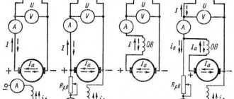
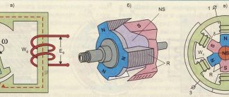
- Depending on the design, these generators are usually divided into structural and specially designed generators. The high frequency generator of conventional design is equipped with a multi-pole rotor, it operates at a maximum speed of 3000 rpm and a frequency of up to 200-400 Hz. Their design differs from a conventional synchronous generator only in the Rotor, the heart device Fig. 13.8. Structure of the beak-like pole device of the Rotor. The nickname adopted from the electric steel sheet has a large number of different poles with field coils. The latter is firmly fixed in the groove between the poles of the texolite or bronze wedge. The appearance of the Rotor is similar to the appearance of an asynchronous machine with a winding phase. At higher frequencies (400-800 Hz) and low power, a generator with a beak-shaped pole on the rotor and 1 common excitation winding for all poles located around the circumference of the rotor with iodine poles is sometimes used (Fig. 13.8).
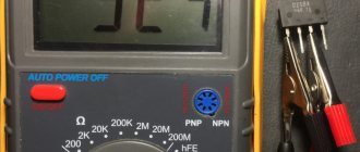
Description of the frequency generator
A frequency generator came to me straight from China. As you can see, it is a pretty solid device.
On the front panel of the frequency generator we see many different buttons and knobs. This knob is designed to decrease or increase the amplitude of the signal.
These buttons are designed to change the waveform.
Here you can see signals such as
rectangular
triangular
sinusoidal
Next, using the buttons, you can select the desired range, as well as connect any external signal.
By external counter we mean any periodic signal from some frequency generator or circuit. By applying such a signal to the connector of our frequency generator, we can easily determine the frequency of an unknown signal up to 10 Megahertz. That is, in this case, the function generator acts as a frequency meter.
Next are the connectors.
VCF – V oltage C ontrolled F requency. According to our VCO . Stands for Voltage Controlled Generator . _ The name itself tells us that we can change the frequency of the signal from the frequency generator by applying any voltage to this connector. Depending on the amplitude of the supplied voltage, this will be the frequency at the output of the frequency generator.
TTL OUT. TTL – Transistor- Transistor - Logic . OUT – output. This output is intended for clocking logic chips built on the so-called transistor-transistor logic. That is, these are logical elements that contain only bipolar transistors and resistors. Such microcircuits are made mainly for +5 V power supply.
Logical zero is a voltage level from 0 to +0.5 V. Logical one level is from 2.4 to +5 V. Therefore, from this output we receive a rectangular periodic signal with alternating zeros and ones: 0101010101... The frequency of such a signal set using the knob and range selection buttons.
OUTPUT . Generator output. It is from this connector that we receive the signal we need from the function generator.
Also of little interest may be the buttons
It says “attention”, which means “attention”. It should actually say “attenuator”. Attenuator is not our word, it means “to weaken, soften.” Apparently, the Chinese saved money on a translator from Chinese to English). So, what are the -20dB and -40dB buttons? dB is decibels. In the meantime, here is a link to an online calculator. I have already calculated everything for you. -20dB means that we can attenuate the signal produced by the generator by 10 times. -40dB – 100 times. And if we press 2 buttons at once, then we get a total of -60dB. Therefore, we can attenuate the signal by a factor of 1000.
General description of the HF device
Most ordinary people use this device to stop the meter. A high-frequency generator is really capable of stopping the operation of such equipment by creating oscillations. In addition, this device can also be used to power common household devices. If we talk about power, the output voltage reaches 220 A, and the power is 1 kW. It is also possible to replace some elements with more powerful ones. If this is done, the output characteristics of the high-frequency generator will increase, and with its help it will be possible to power a larger number of units or several, but more powerful ones. The HF itself is connected to a regular household network. It is important to note here that the electrical wiring diagram is quite simple, and there is no point in changing it in any way. In addition, there is no need to use a grounding system for this device. When such oscillating units are connected to the network, they do not completely stop the operation of the meter. The unit continues to operate, but only 25% of the actual electricity consumption is recorded.
Dangerous fun: an easy-to-replicate high voltage generator
Good afternoon, dear Khabrovsk residents. This post will be a little unusual. In it I will tell you how to make a simple and fairly powerful high-voltage generator (280,000 volts). I took the Marx Generator circuit as a basis. The peculiarity of my scheme is that I recalculated it for accessible and inexpensive parts. In addition, the circuit itself is easy to repeat (it took me 15 minutes to assemble it), does not require configuration and starts the first time. In my opinion, it is much simpler than a Tesla transformer or a Cockroft-Walton voltage multiplier.
Principle of operation
Immediately after switching on, the capacitors begin to charge. In my case, up to 35 kilovolts. As soon as the voltage reaches the breakdown threshold of one of the arresters, the capacitors through the arrester will be connected in series, which will lead to a doubling of the voltage on the capacitors connected to this arrester. Because of this, the remaining spark gaps are triggered almost instantly, and the voltage on the capacitors adds up. I used 12 steps, which means the voltage should be multiplied by 12 (12 x 35 = 420). 420 kilovolts are almost half-meter discharges. But in practice, taking into account all the losses, the resulting discharges were 28 cm long. The losses were due to corona discharges.
About details:
The circuit itself is simple, consisting of capacitors, resistors and arresters. You will also need a power source. Since all the parts are high-voltage, the question arises, where to get them? Now, first things first:
1 - resistors
Resistors needed are 100 kOhm, 5 watt, 50,000 volt.
I tried many factory resistors, but none could withstand such voltage - the arc would break through the top of the case and nothing would work. Careful googling yielded an unexpected answer: the craftsmen who assembled the Marx generator for voltages of more than 100,000 volts used complex liquid resistors, the Marx generator on liquid resistors, or used a lot of stages. I wanted something simpler and made resistors from wood. I broke off two even branches of a damp tree on the street (dry ones do not conduct current) and turned on the first branch instead of a group of resistors to the right of the capacitors, the second branch instead of a group of resistors to the left of the capacitors. It turned out to be two branches with many conclusions at equal distances. I made conclusions by winding bare wire over branches. Experience shows that such resistors can withstand voltages of tens of megavolts (10,000,000 volts)
2 - capacitors
Everything is simpler here. I took capacitors that were the cheapest on the radio market - K15-4, 470 pF, 30 kV (aka greensheets). They were used in tube TVs, so now you can buy them at a disassembly site or ask for them for free. They withstand a voltage of 35 kilovolts well, not a single one has broken through.
3 - power supply
I just couldn’t bring myself to assemble a separate circuit to power my Marx generator.
Because the other day my neighbor gave me an old TV “Electron TC-451”. The anode of the kinescope in color televisions uses a constant voltage of about 27,000 volts. I disconnected the high-voltage wire (suction cup) from the anode of the kinescope and decided to check what kind of arc would be produced from this voltage. Having played enough with the arc, I came to the conclusion that the circuit in the TV is quite stable, can easily withstand overloads, and in the event of a short circuit, the protection is triggered and nothing burns out. The circuit in the TV has a power reserve and I managed to overclock it from 27 to 35 kilovolts. To do this, I twisted the R2 trimmer in the TV power module so that the horizontal power supply rose from 125 to 150 volts, which in turn led to an increase in the anode voltage to 35 kilovolts. When you try to increase the voltage even more, the KT838A transistor breaks through in the horizontal scan of the TV, so you need to not overdo it.
Build process
Using copper wire, I screwed the capacitors to tree branches.
There must be a distance of 37 mm between the capacitors, otherwise an unwanted breakdown may occur. I bent the free ends of the wire so that there was 30 mm between them - these will be the arresters. It's better to see once than to hear 100 times. Watch the video where I showed in detail the assembly process and operation of the generator:
Safety precautions
Particular care must be taken, since the circuit operates at a constant voltage and a discharge from even one capacitor will most likely be fatal.
When turning on the circuit, you need to be at a sufficient distance because electricity penetrates 20 cm or even more through the air. After each shutdown, you must always discharge all capacitors (even those in the TV) with a well-grounded wire. It is better to remove all electronics from the room where the experiments will be carried out. The discharges create powerful electromagnetic pulses. The phone, keyboard and monitor that are shown in my video are out of order and can no longer be repaired! Even in the next room my gas boiler turned off.
You need to protect your hearing. The noise from the discharges is similar to gunshots, then it makes your ears ring.
Interesting observations
The first thing you feel when you turn it on is how the air in the room is electrified.
The electric field intensity is so high that it is felt by every hair of the body. The corona discharge is clearly visible. Beautiful bluish glow around parts and wires. There is always a slight electric shock, sometimes you don’t even understand why: you touched the door - a spark jumped, you wanted to take the scissors - the scissors shot. In the dark, I noticed that sparks were jumping between various metal objects not connected with the generator: in a briefcase with a tool, sparks were jumping between screwdrivers, pliers, and a soldering iron.
The lights light up on their own, without wires.
The whole house smells like ozone, like after a thunderstorm.
Conclusion
All parts will cost about 50 UAH ($5), this is an old TV and capacitors.
Now I am developing a fundamentally new scheme with the goal of obtaining meter discharges without special costs. You ask: what is the application of this scheme? I will answer that there are applications, but they need to be discussed in another topic. That's all for me, be careful when working with high voltage.
Operation of the device
If you look in more detail at the operation of a high-frequency generator, then the equipment stops due to the fact that a capacitor is used in the device circuit. The connection is made precisely to this part, which has a charge that completely coincides with the sinusoid of the voltage flowing in the network. The charge is carried out through pulses with high frequency. Thus, it turns out that the current that the consumer consumes from his home network becomes a high-frequency pulse. Conventional electronic meters installed in homes are characterized by a lack of sensitivity to such fluctuations. This means that the unit will take into account the pulse current consumption with a negative error.
Description of the scheme
The high-frequency generator circuit is characterized by the presence of certain key elements. These include: rectifier, capacitor, transistor. Further, if we talk about connecting the capacitor, then it is connected in series with the rectifier. This is necessary so that while the rectifier is working on the transistor, the capacitor can be charged to the voltage that is available in the network.
Most often, the capacitor charging limit in a high-frequency generator becomes 2 kHz. If we talk about the voltage that is currently present across the load and capacitance of the device, then it approaches the sine wave of 220 V. In order to limit the current flowing through the transistor while the capacitance is charging, there is a resistor in the circuit that is connected with key cascade using a serial connection.
LOW FREQUENCY GENERATOR
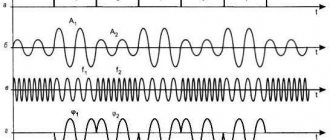
The low frequency generator is assembled using transistors VT1 and VT3. The positive feedback necessary for generation to occur is removed from resistor R10 and supplied to the base circuit of transistor VT1 through capacitor C1 and the corresponding phase-shifting circuit selected by switch B1 (for example, C2, C3, C12.). One of the resistors in the chain is a tuning resistor (R13), with which you can adjust the frequency of generation of a low-frequency signal. Resistor R6 sets the initial bias based on transistor VT1. Transistor VT2 contains a circuit for stabilizing the amplitude of the generated oscillations. The sinusoidal output voltage through C1 and R1 is supplied to the variable resistor R8, which regulates the output signal of the low-frequency generator and regulates the depth of amplitude modulation of the high-frequency generator.
HIGH FREQUENCY GENERATOR
The RF generator is implemented on transistors VT5 and VT6. From the output of the generator, through C26, the signal is fed to an amplifier assembled on transistors VT7 and VT8. An RF signal modulator is assembled using transistors VT4 and VT9. The same transistors are used in the output signal amplitude stabilization circuit. It wouldn’t be a bad idea to make an attenuator for this generator, either T or P type. Such attenuators can be calculated using the appropriate calculators for calculating T-attenuators and P-attenuators. That seems to be all. Goodbye. K.V.Yu.
Download the diagram.
Features of HF performance
The generator is executed entirely on logical elements. It produces oscillations or pulses with a frequency of 2 kHz and an amplitude of 5 Volts. There is also such a characteristic as the signal frequency. The value of this parameter is determined by elements C2 and R7. Standard notation schemes use this signature format. The properties that these elements provide can be used to adjust the maximum error in metering energy consumption. Elements such as T2 and T3 - transistors - are responsible for creating pulses. Together they are called the impulse creator. This part is also responsible for the correct operation of transistor T1.
High frequency signal generator G4-151
The main purpose of such a generator is to configure, check, adjust and test radio devices. Using this device, it is possible to measure the amplitude-frequency response, sensitivity, selectivity, etc. In addition, this equipment can also be used as a signal source that works with different methods of oscillation modulation. This can be amplitude, frequency or pulse modulation. It is also possible to create unmodulated oscillations. Most often, such equipment is used in verification bodies, in equipment repair shops, in workshops or laboratories.
The output of this high-frequency signal generator is a regular digital code. In addition, for ease of control, there are analog inputs that allow you to remotely adjust all parameters of the device.
Types of signal generators
The devices differ in a number of characteristics. For example, by signal shape (sinusoidal, rectangular, saw-tooth), by frequency (low-frequency, high-frequency), by the principle of excitation (independent, self-excitation). However, there are several main types - we will tell you about them in more detail.
Sinusoidal
The device amplifies the original sinusoidal code tens of times. The output frequency is up to 100 MHz. In this case, the initial sine, as a rule, does not exceed 50 MHz. Sine wave generators are actively used when testing power supplies, inverters and other high-frequency equipment, as well as radio equipment.
Low frequency generator
Below is a diagram of the simplest low-frequency generator. It shows that the device contains variable resistors. They allow you to adjust the shape and frequency of the signal. You can change the pulse strength using the connected KK202 modulator.
This device is suitable for setting up audio equipment (sound amplifiers, players). The most affordable option for a low-frequency generator is a regular computer. Just download the drivers and connect it to the equipment via an adapter.
Audio frequency generator
Standard design with microcircuits inside. The voltage is supplied to the selector, and the signal itself is generated in one or more microcircuits. The frequency can be adjusted using a modulation controller. The device has a wider frequency range than its analogues (up to 2000 kHz).
Arbitrary pulses
Arbitrary pulse generators have increased accuracy. The error is minimal - up to 3%. The output pulse is finely adjusted using a six-channel selector. The device produces a frequency of 70 Hz.
Devices are divided according to the degree of synchronization. It depends on the type of connector that is installed in the device. Therefore, the signal can be amplified in 15-40 newton seconds. Some models operate in 2 modes - linear and logarithmic. The mode is changed with a switch, due to which the amplitude is adjusted.
Complex Signal Controllers
The assembly contains only multi-channel selectors, since the devices receive pulses of complex shapes. The signals are amplified many times, the mode can be changed using the regulator. A variation of such a device is considered to be a DDS (direct digital synthesis device).
The base board is equipped with microcontrollers that can be easily removed and replaced. In some models, you can replace the microcontroller with one click. If the editor is mounted, limiters cannot be set. The device generates a measuring signal with a power of up to 2000 kHz with an error of up to 2%.
Digital signal generator
Digital generators are popular because they are highly accurate. They are convenient to use, but they require careful configuration. There are KP300 connectors here, resistors reach a resistance of 4 ohms. This allows you to achieve the maximum permissible internal voltage in the circuit.
Areas of use
Signal generators are used in modern electronic and instrumentation development laboratories. The same generators can be used in classrooms from beginner to advanced levels.
However, these functional devices are used for setting up and testing equipment and in areas that are more accessible to the average person. Here is just a partial list of devices that use generators:
- mobile phones, data transmission equipment, radio and television receivers;
- computing devices;
- inverters, uninterruptible power supplies from electricity or pulses;
- household appliances (microwave ovens, washing machines and dishwashers);
- measuring instruments (ammeters, voltmeters, oscilloscopes);
- medical equipment (tomographs, electrocardiographs, ultrasound machines).
Resourceful users also use devices for other purposes. For example, the Tektonix AFG 3000 device was used to measure capacitances, and the RStamp SMA100A performed well in adjusting aeronautical systems.
Personal assembly
Since it can be difficult to assemble a real high-frequency generator circuit with your own hands, there is a somewhat simplified assembly option. In this case, instead of a transistor, an element with negative resistance will be used in the circuit. Such elements are also often called reinforcing elements. To put it in very simple words, the current at the output of such devices is always greater than the current at their input.
An oscillatory circuit is connected to the input of such a device. Next, it is very important to connect the output of the same amplifier through feedback to the same oscillatory circuit. By connecting the circuit in this way, you get the following result. A current of a certain value is supplied to the input, passing through the amplifying element, it increases, which energizes the loop capacitor. With the help of feedback, the already amplified current returns again to the input of the circuit, where it is again amplified. This circular process happens all the time. It is this that causes undamped oscillations inside the generator.
Add a link to a discussion of the article on the forum
RadioKot >Training >Analog technology >Bugs, transmitters and receivers: what you need to know about them >
| Article tags: | Add a tag |
RF Generators
Author: Published 01/18/2006
So, the most important block of any transmitter is the generator. How stable and accurate the generator operates determines whether someone can pick up the transmitted signal and receive it normally.
There are simply a lot of different bug circuits lying around on our beloved Internet, which use various generators. Now we are a little classifying this lot.
The ratings of the parts of all the given circuits are calculated taking into account the fact that the operating frequency of the circuit is 60...110 MHz (that is, it covers our favorite VHF band).
"Classics of the genre".
The transistor is connected according to a common base circuit. The resistor voltage divider R1-R2 creates an operating point offset on the base. Capacitor C3 shunts R2 at high frequency.
R3 is included in the emitter circuit to limit the current flowing through the transistor.
Capacitor C1 and coil L1 form a frequency-setting oscillatory circuit.
Conder C2 provides the positive feedback (POF) necessary for generation.
Generation mechanism
A simplified diagram can be represented as follows:
Instead of a transistor, we put a certain “element with negative resistance”. In essence, it is a reinforcing element. That is, the current at its output is greater than the current at the input (so that’s tricky).
An oscillatory circuit is connected to the input of this element. Feedback is supplied from the output of the element to the same oscillatory circuit (via capacitor C2). Thus, when the current at the input of the element increases (the loop capacitor is recharged), the current at the output also increases. Through feedback, it is fed back to the oscillatory circuit - “feeding” occurs. As a result, undamped oscillations settle down in the circuit.
Everything turned out to be simpler than steamed turnips (as always).
Varieties
On the vast Internet you can also find the following implementation of the same generator:
The circuit is called "capacitive three-point". The operating principle is the same.
In all these schemes, the generated signal can be removed either directly from the collector VT 1, or use a coupling coil connected to a loop coil for this purpose.
Inductive three-point.
I choose this scheme and recommend it to you.
R1 – limits the generator current,
R2 – sets the base offset,
C1, L1 – oscillatory circuit,
C2 – Conder POS
Coil L1 has a tap to which the emitter of the transistor is connected. This tap should not be located exactly in the middle, but closer to the “cold” end of the coil (that is, the one that is connected to the power wire). In addition, you can not make a tap at all, but wind an additional coil, that is, make a transformer:
These schemes are identical.
Generation mechanism:
To understand how such a generator works, let's look at the second circuit. In this case, the left (according to the diagram) winding will be the secondary, the right - the primary.
When the voltage on the upper plate of C1 increases (that is, the current in the secondary winding flows “up”), an opening pulse is applied to the base of the transistor through the feedback capacitor C2. This causes the transistor to apply current to the primary winding, this current causes the current in the secondary winding to increase. There is a replenishment of energy. In general, everything is also quite simple.
Varieties.
My little know-how: you can put a diode between the common and the base:
This diode accelerates the recharge of C2, which leads to an increase in the power of the generated signal. However, at the same time, this introduces nonlinear distortions into the signal, so you will have to install low-pass filters at the output to suppress spurious harmonics.
The signal in all these circuits is removed from the emitter of the transistor or through an additional coupling coil directly from the circuit.
Push-pull generator for the lazy
The simplest generator circuit I've ever seen:
In this circuit one can easily see the similarity with a multivibrator. I'll tell you more - this is a multivibrator. Only instead of delay circuits on a capacitor and resistor (RC circuit), inductors are used here. Resistor R1 sets the current through the transistors. In addition, without it, generation simply will not work.
Generation mechanism:
Let's say VT1 opens, collector current VT1 flows through L1. Accordingly, VT2 is closed, and the opening base current VT1 flows through L2. But since the resistance of the coils is 100...1000 times less than the resistance of resistor R1, then by the time the transistor is fully opened, the voltage across them drops to a very small value, and the transistor closes. But! Since before closing the transistor, a large collector current flowed through L1, at the moment of closing there is a voltage surge (self-induction emf), which is supplied to the base of VT2 and opens it. Everything starts over again, only with a different generator arm. And so on…
This generator has only one advantage - ease of manufacture. The rest are cons.
Since it does not have a clear timing link (oscillating circuit or RC circuit), it is very difficult to calculate the frequency of such a generator. It will depend on the properties of the transistors used, the supply voltage, temperature, etc. In general, it is better not to use this generator for serious things. However, in the microwave range it is used quite often.
Push-pull generator for hard workers
The other generator that we will consider is also a push-pull generator. However, it contains an oscillatory circuit, which makes its parameters more stable and predictable. Although, in essence, it is also quite simple.
Here he is
What do we see here?
We see the oscillatory circuit L1 C1, And then we see a pair for each creature: Two transistors: VT1, VT2 Two feedback capacitors: C2, C3 Two bias resistors: R1, R2
An experienced eye (and not a very experienced one) will find in this circuit similarities with a multivibrator. Well, that’s how it is!
What is special about this scheme? Yes, because due to the use of push-pull switching, it allows you to develop double power, compared to circuits of 1-cycle generators, at the same supply voltage and provided that the same transistors are used. Wow! Well, in general, she has almost no flaws
Generation mechanism
When the capacitor is recharged in one direction or the other, current flows through one of the feedback capacitors to the corresponding transistor. The transistor opens and adds energy in the “right” direction. That's all the wisdom.
I have not seen any particularly sophisticated versions of this scheme...
Now for a little creativity.
Logic element generator
If the use of transistors in a generator seems outdated or cumbersome to you, or unacceptable for religious reasons, there is a way out! Microcircuits can be used instead of transistors. Logic is usually used: the elements NOT, AND-NOT, OR-NOT, less often - Exclusive OR. Generally speaking, only NOT elements are needed, the rest are excesses that only worsen the speed parameters of the generator.
Let's look:
We see a terrible scheme.
The squares with a hole in the right side are inverters. Well, or – “elements NOT”. The hole just indicates that the signal is inverted.
What is the element NOT from the point of view of banal erudition? Well, that is, from the point of view of analog technology? That's right, this is an amplifier with a reverse output. That is, as increases , the output voltage decreases . The inverter circuit can be depicted something like this (simplified):
This is of course too simple. But there is some truth in this. However, this is not so important to us for now.
So, let's look at the generator circuit. We have:
Two inverters (DD1.1, DD1.2)
Resistor R1
Oscillatory circuit L1 C1
Note that the oscillating circuit in this circuit is series. That is, the capacitor and the coil are located next to each other. But this is still an oscillatory circuit, it is calculated using the same formulas, and is no worse (and no better) than its parallel counterpart.
Start over. Why do we need a resistor?
The resistor creates negative feedback (NFB) between the output and input of element DD1.1. This is necessary in order to keep the gain under control - this is one, and also - to create an initial bias at the input of the element - this is two. We will look at how this works in detail somewhere in the tutorial on analog technology. For now, let’s understand that thanks to this resistor, at the output and input of the element, in the absence of an input signal, a voltage equal to half the supply voltage settles. More precisely, the arithmetic mean of the voltages of logical “zero” and “one”. Let’s not worry about this for now, we still have a lot to do...
So, on one element we got an inverting amplifier. That is, an amplifier that “turns” the signal upside down: if there is a lot at the input, there is little at the output, and vice versa. The second element serves to make this amplifier non-inverting. That is, it flips the signal over again. And in this form, the amplified signal is supplied to the output, to the oscillatory circuit.
Come on, let's look carefully at the oscillatory circuit? How is it enabled? Right! It is connected between the output and input of the amplifier. That is, it creates positive feedback (POF). As we already know from reviewing previous generators, POS is needed for a generator like valerian is for a cat. Without POS, not a single generator can do what? That's right - get excited. And start generating...
Everyone probably knows this thing: if you connect a microphone to the input of an amplifier and a speaker to the output, then when you bring the microphone to the speaker, a nasty “whistle” begins. This is nothing more than generation. We feed the signal from the amplifier output to the input. A POS appears. As a result, the amplifier begins to generate.
Well, in short, by means of an LC circuit, a PIC is created in our generator, leading to excitation of the generator at the resonant frequency of the oscillatory circuit.
Well, is it difficult? If
(difficult) { scratch (turnip) ; read again; }
Now let's talk about the types of such generators.
Firstly, instead of an oscillating circuit, you can turn on quartz. The result is a stabilized generator operating at the quartz frequency:
If you include an oscillating circuit instead of a resistor in the OS circuit of element DD1.1, you can start a generator using quartz harmonics. To obtain any harmonic, it is necessary that the resonant frequency of the circuit be close to the frequency of this harmonic:
Tube RF
One of the types of high-frequency signal generators is tube devices. Such devices are used to obtain plasma with the required parameters. To do this, you need to apply a certain discharge to the power of the device. The key elements of such devices are emitters, the operation of which is based on the principle of power supply.
Power amplifiers are another important element for tube HF operation. These parts, installed on lamps, are used to convert direct current into alternating current. Naturally, the operation of a lamp generator is impossible without the lamp itself. You can use various elements. The GU-92A tetrode has become quite common. This part is an electron tube, the operation of which uses four elements: anode, cathode, shielding and control grids.
Source