- home
- >Manufacture of generators
The main indicator of a generator is voltage, and knowing the voltage, you can calculate all other parameters, such as the battery charging current and the power of the generator as a whole. A generator is usually built to charge batteries, and for this we will try to calculate the generator. The voltage of the generator coils depends on the number of turns in the coils, on the magnetic induction of the magnets, and on the speed at which the magnetic field changes. Simply put, the faster the magnets move past the coils, the higher the voltage.
To calculate the generator voltage we will use a simple formula, it is very simple and should not cause problems. You can read more details with an example here - Calculation of the EMF of a generator. The phases and connections of the coils will be discussed below, but for now let’s look at the generator voltage.
Formula E=B V L
where: E is the generator voltage (V). B-magnetic induction of magnets (T). V-speed of movement of magnets (m/s). L-active conductor length (m).
With the letter E is the voltage of the generator, which we need to calculate, and then the letter B - which is not known, since we do not know what the magnetic induction of the magnets is. But if you search the search engine and read the forums, you can find out that the magnetic induction of neodymium magnets is about 1.25 T, of course it is different for different brands of magnets, but this is the average value. It is also known that the further away from the magnet, the less magnetic induction. In general, if, in the case of manufacturing a disk generator, the distance between the magnets on opposite disks is equal to the thickness of the magnets, then the magnetic induction will be approximately 1.0 T; if the distance is greater, then naturally the magnetic field will be weaker. If, for example, you have magnets 10 mm thick, and you make the distance between the magnets 10 mm, then the induction will be somewhere around 1.0 T, and the stator in this case will be no more than 8 mm thick, and 1 mm for the gaps. If the distance is, say, 12-14 mm, then the magnetic induction will drop to 0.8-0.7 T and below.
For generators with iron, the principle is the same, but the thickness of the magnets can be different, some use magnets with a thickness of 10-15mm, although for a magnetic induction of 1.0T a magnet thickness of 3-4mm is sufficient. Another important thing is the thickness - the magnetic transmittance of the stator, on the teeth of which the coils are wound. If you go too far with the thickness of the magnets, the stator will not be able to close the entire magnetic field and it will come out, and iron will be magnetized to the stator from the outside. That is, this is a loss of the magnetic field and there is no point in using too powerful magnets since part of the magnetic field will not be used. Everything, of course, depends on specific conditions, but if the magnetic induction is not known, then it is better to take it as 0.8-1 T.
Let's return to the formula, V is the speed of movement of the magnets, it is very simple to calculate. For example, if the diameter of the rotor with magnets is 20 cm, then 20 * 3.14 = 62.8 cm. That is, it turns out that in one revolution the magnets travel a distance of 62.8 cm or 0.62 meters. If the rotor diameter is 8cm, then similarly 8*3.14=25.12cm or 0.25m.
L is the active length of the conductor, that is, this is the length of the copper wire that falls under the magnets, because it is only that section of the wire that generates electricity that falls under the magnetic field of the magnets. For disk axial generators, the length of the active conductor is equal to the length of the magnets. For example, if you have round magnets measuring 30*10mm, then L=30mm, but if rectangular magnets measuring 50*30*10mm, then L=50mm. For generators with an iron stator, the active length of the conductor is equal to the width of the stator.
Active conductor length
Active conductor length, calculation of generator coils
Now let's try to calculate the generator voltage, but first we'll deal with the generator coils
Generators come in both single-phase and three-phase. As a rule, beginners make single-phase generators considering them simpler, but single-phase ones hum during operation, since the number of magnets and coils in such generators is the same. And it turns out that when the magnets run into the coils, the coils resist this and repel the magnets. As a result, there seems to be a peak in resistance and a decline, which causes buzzing and vibration. Three-phase ones are designed differently, there is a 2/3 displacement of the coils relative to the magnets, and due to this the load is evenly distributed, which makes the vibration much lower. Also, the power characteristics are somewhat better, and the circuit is not much complicated.
Below is a connection diagram for a single-phase generator
EMF regulation
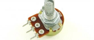
Due to changes in the parameters of active loads, there is a need to equalize the rated voltages. Despite the fact that the induced emf of a synchronous generator is related to the rotor rotation speed, however, due to the requirements for maintaining a stable frequency, this parameter cannot be changed in this way. But the parameters of magnetic induction can be changed by reducing or increasing the magnetic flux, which depends on the number of turns of the inductor winding and the magnitude of the excitation current.
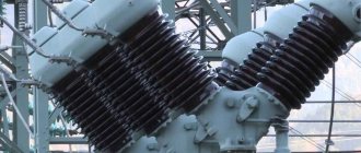
Regulation is carried out by connecting additional rheostats, electronic circuits to the excitation coil circuit, or by adjusting the current of the exciter generator (Fig. 4). In the case of using alternators with permanent magnets, the voltage in such devices is regulated by external stabilizers.
Rice. 4. Voltage regulation circuit
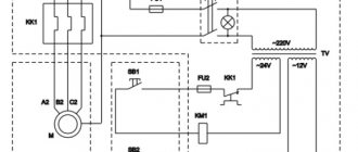
Due to their low weight and excellent current characteristics, synchronous alternating current generators are used in all modern cars. Since the car's on-board network uses direct current, car generator designs are equipped with a three-phase rectifier. For rectified alternating currents, the frequency does not matter, but the voltage must be stable. This is achieved using external electronic devices. Figure 5 shows an electrical diagram for connecting the generator to the on-board network of a modern car.
Rice. 5. Connection diagram of the generator to the vehicle’s on-board network
Coil connection
connection of coils of a single-phase generator Coils of a single-phase generator are connected like this
, the beginning of the first to the output (diode bridge), and the end is connected to the end of the second coil, the beginning of the second to the beginning of the third, the end of the third to the end of the fourth, the beginning of the fourth to the beginning of the fifth coil, and so on until last reel.
Connection of three-phase generator coils
Security measures
When diagnosing a module, it is recommended to adhere to the following rules:
- do not close contacts;
- do not allow water to enter;
- store the battery separately;
- monitor the tightness of the structure;
- check the voltage level.
When removing the generator, the components are checked. Attention is paid to the operating rules according to the instructions. The installations operate in certain modes, and the main characteristics are assessed. Modules are afraid of salt and liquids. Installation of the generator must be carried out by a specialist.
If you connect the generator to a car, you need to check the power rectifier. It is necessary to remove the exciter windings, as well as the phase. The voltage regulator is checked separately. During installation, it is prohibited to check until fully connected.
The concept of a voltage generator is described in detail above. The basic operating principle and characteristics are described. The amperage, rotation speed and connection diagram are taken into account.
Coil connection
connection of the coils of a three-phase generator, in the figure there is a stator consisting of 15 coils. The coils of a three-phase generator are connected like this
: The beginning of the first coil with the end of the fourth, and the beginning of the fourth with the end of the seventh, the beginning of the seventh with the end of the tenth, the beginning of the tenth with the end of the thirteenth, and the beginning of the thirteenth with exit along with the end of the first. The remaining two phases are similar starting from the second coil, and the third phase from the third. In the figure, the stator consists of 15 coils, and the disks should have 10 magnets. If the stator consists of 9 coils, then there are three coils per phase, and the disks can have either six pairs of magnets or 12 pairs.
Let's return to the formula E=B·V·L
. For example, it is planned to wind 18 coils with 1.0 mm wire, and 80 turns are placed in the coil, which means that in total we have 18 * 80 = 1440 turns. If the generator is single-phase, then we calculate this for all coils, and if it is three-phase, then we will take coils of one phase, in this case six coils in a phase, and then we will calculate the data for a star or triangle connection. I will consider three-phase, so I take six coils 80 * 6 = 480 turns.
Our magnets, for example, are 30*10mm (12 pieces per disk), which means the active length of the conductor is 0.03m; if the stator is iron, then the width of the stator is taken. For example, we have disks with magnets with a diameter of 20 cm, but we need to take the diameter at the center of the magnets, which means minus 1.5 cm in a circle and that’s 20-3 cm = 17 * 3.14 = 53.38 cm or 0.53 m. I would like to remind you that the thickness of the iron disks must be no less than the thickness of the magnets, otherwise the magnetic field will go beyond the iron and will not participate in the generation of electricity and the magnetic induction will be lower, and if you have, for example, the rotor of an asynchronous motor, then after grooving it is advisable to put on a metal sleeve and glue magnets onto it, or grind out an all-metal rotor, this way the magnets will be used more efficiently and you can either get more power or save on the thickness of the magnets.
And so now we have the necessary data to calculate the generator voltage, for example, at 60 rpm. Let's take the magnetic induction equal to 1 T. The speed of movement of the magnets per revolution is 0.53 m, which means that at 60 rpm there will be 1 rpm, that is, 0.53 m/s is the speed of movement of the magnets. The active length of the conductor is also known to us and is equal to 0.03 m. Then 0.03m needs to be multiplied by the number of turns in the coil (80) and the number of coils (6), and you get 0.03*480=14.4m.
Now we represent the values in the formula E=B(1T)*V(0.53m)*L(14.4m), it turns out E=7.632V. In general, at 60 rpm the phase voltage is 7.6 volts. The generator voltage increases linearly depending on the speed, which means that at 120 rpm it will be 15.2 volts, and at 240 rpm it will be 30.4 volts. And at 300 rpm there will be 38.0 volts. Charging will start at 120 rpm if you connect the generator phases with a triangle. When connected by a star, the generator voltage will be 1.7 times higher, which means charging will begin even earlier, at 90 rpm.
But if you draw a virtual stator with coils and magnets, you can see that the magnet does not completely cover the coil and 30% of the active zone does not overlap no matter how the magnet is standing, which means that 30% is not involved in generating voltage and this must be taken into account. It often happens that the magnet covers only half of the coil, and this means that only half of the turns are involved in generating electricity. This means that in our case the voltage will be 30% lower than it turned out, that is, not E=7.632V, but E=5V.
Now let's talk about the generator current, its resistance and star-delta connection
We can now determine the voltage and adjust the start of charging to the propeller of the wind generator, so that the propeller can unwind and charging begins in a weak wind.
But charging is carried out with current in amperes, and the current strength depends on the resistance of the coils and the load as a whole (wires and battery). The lower the resistance, the higher the charging current and the lower the heating losses; therefore, the resistance of the generator winding should be made as small as possible. In our generator, consisting of 18 coils, there are only 18 * 80 = 1440 turns, which is 480 turns per phase. To find out the phase resistance you need to find out the length of the wire in the phase and its cross-section. The average length of one turn is approximately 0.08m, which means 0.08*480=38.4m. The resistance of one meter of copper wire with a cross section of 1 mm is 0.0224 Ohm. Next 38.4*0.0224=0.86 Ohm.
Application of alternating current generators in practice
Industrial production of powerful generators
Such generators are used in almost all areas of human activity where electrical energy is required. Moreover, the principle of its extraction differs only in the method of driving the device shaft. This is how hydro, heat and even nuclear power plants work.
These stations power public networks via wires, to which the end consumer, that is, all of us, connects. However, there are many objects to which it is impossible to deliver electrical energy in this way, for example, transport, construction sites far from power lines, very distant villages, shifts, drilling rigs, etc.
This means only one thing - you need your own generator and engine to drive it. Let's look at several small and common devices in our lives.
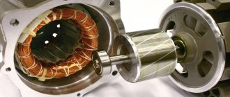
Car generators
In the photo - an electric generator for a car
Someone might immediately say: “How? This is a DC generator!” Yes, indeed, it is so, but what makes it so is only the presence of a rectifier, which makes this very current constant. The basic principle of operation is no different - the same rotor, the same electromagnet, etc.
Schematic diagram of a car generator
This device operates in such a way that, regardless of the shaft rotation speed, it produces a voltage of 12V, which is provided by the regulator through which the field winding is powered. The excitation winding starts, powered by a car battery, the rotor of the unit is driven by the car engine through a pulley, after which an EMF begins to be induced.
Several diodes are used to rectify three-phase current.
Copper Wire Resistance Table
Now we know the phase resistance, which is 0.86 Ohm. If you connect the generator with a star, then the total resistance of the generator will increase by 1.7, and so will the voltage, and if with a triangle, then the total resistance will remain equal to one phase, and the voltage will also be equal to the phase. With a star, the resistance will become 0.86*1.7=1.46 Ohm.
To find out what the battery charging current will be, you need to know the generator voltage and its resistance, which we already know. To calculate, you need to subtract the generator voltage from the no-load voltage of the generator, and divide the resulting amount by the resistance, and you get the charging current. For example, when connected by a star at 120 rpm, the idle voltage is 10V * 1.7 = 17 volts. Then from 17 volts we subtract the battery voltage of 17-13 volts and get a difference of 4 volts, divide by the resistance of 1.46 Ohms, and get 4: 1.46 = 2.7 Amperes. And so you can calculate the current strength at each generator speed, and to get the charging power you need to multiply amperes by volts, in this case 2.7*13=35.1 watt*h. And already at 240 rpm the voltage at idle will be twice as high, since it increases linearly, then 20V-13 = 7: 1.46 = 4.7 Amperes.
But here, not only the resistance of the generator itself plays a role, but also the resistance of the wire from the generator to the battery, the resistance of the diode bridge, on which the voltage drops to 1 volt, and the resistance of the battery itself. All this can be calculated, but it is quite difficult. The resistance of the generator also changes during operation, so the amount of total losses can be up to 50% of the power, and as a result, the charging current can be half the calculated one. And since it is difficult to take everything into account, on average you can reduce losses by 30%, which means that the battery will actually receive a current not of 4.7 Amperes at 240 rpm, but much lower, about 3.5-4 Amperes.
Such a calculation gives a rough idea of the future generator, but it’s still better than doing whatever it takes without taking anything into account, and then being surprised that either the voltage is too low or high, or the resistance is too high and the charging current is ridiculous. Having calculated my generators, I was convinced of the validity of this generator calculation.
When calculating the generator, you need to take into account that it will be rotated by the wind wheel of the wind generator, and the wind wheel has its own speed, and the generator must be at least approximately made to fit the future propeller. If it is a vertical windmill, then its wind wheel rotates very slowly compared to a horizontal propeller. And in this regard, it is necessary that charging begins at very low generator speeds. In order for charging to start early, the voltage must be higher than the battery voltage, hence it is necessary to have as many turns as possible in the coils. But the more turns, the longer the wire, and therefore the resistance, and the resistance determines the strength of the charging current. As a result, in order for the generator to be powerful and charging to begin early, it needs to be calculated so that there is both power and the wind wheel is not overloaded - otherwise it will not reach its speed and gain power.
With a horizontal propeller, the generator needed is not as large and material-intensive as for a vertical one; for horizontal propellers, the speed is on average 5 times higher, which is why the generator needed is five times smaller and the same amount cheaper. Calculations of wind turbine wheels are available in other articles from the section “Calculations of wind turbines”. I advise you to familiarize yourself with this material, since a wind generator is a single mechanism and its components must be suitable in parameters for each other, otherwise either the propeller is too powerful and low-speed or the generator is too powerful, and such a windmill will be of little use.
Equipment starting power
It would be more accurate to talk about the starting current of various units that occurs when they are turned on. When, for example, a refrigerator compressor or a submersible pump motor reaches operating mode, it is accompanied by a sharp jump in current consumption from the electrical network. It is not difficult to imagine what this overload will be like for the welding machine. This feature should also be taken into account when calculating the power of the corresponding load in the form of a multiplying factor. Its approximate values for household appliances are as follows:
- refrigerator - 3;
- TV, vacuum cleaner and electric stove - 1.1;
- washing machine - 1.5;
- microwave oven - 2.
For a power tool, the increase factor will be as follows:
- electric drill - 1.1;
- circular saw - 1.5;
- welding machine - 4;
- electric concrete mixer - 3.
It can, however, be noted that a number of diesel generator models use special means to neutralize starting currents in the load. But this system cannot be used for a welding machine due to the principle of its operation. After all, welding is a constant occurrence of starting current.
Generator drawing
Preliminary drawing of the generator to find out what size the coils will be.
Since we have 12 magnets on the disks, then 360:12 = 30, it turns out that the sectors for the magnets are divided by 30 degrees. We have 18 coils, so 360:18 = 20, that is, a 20-degree sector of the coil. A coil should fit in a 20 degree sector, the winding width is 10mm, and the thickness of the stator is 8mm, which means wires with a diameter of 1mm will fit 10*8:1=80 turns. If you wind it with 1.5mm wire, then 10*8:1.5=53 turns will fit. And if the wire diameter is 2mm, then accordingly 80*8*2=40 turns.
Coil dimensions
To fit the generator to the wind wheel, or vice versa, then the wind wheel to the generator, you need to calculate the power of the generator at different speeds, for example, at 120 rpm when the battery starts charging and the load on the wind wheel begins, and then at 180,240,300,360,420,480,540,600 rpm.
Based on the above calculated data, we received 17 volts at 120 rpm, our resistance is 1.46 Ohm. more accurate data will be if you measure the voltage during charging in real time, but for low current I took the battery voltage to be 13 volts, and then proceeded from a voltage of 14 volts. As a result, the following calculations were obtained below, but at higher speeds with a large difference between the no-load voltage and the voltage when charging the battery, the efficiency of the generator will drop and the charging current again will not be so large, although the generator will load the propeller at higher power, the losses will be heating of coils and wires. In general, the charging current will be lower by another 10-20%.
at 120 rpm - 17-13=4:1.46=2.7A*13=35 watts at 180 rpm - 25.5-14=11.5:1.46=7.8A*14=110 watts at 240 rpm - 34-14=20:1.46 =13.6A*14=190 watts at 300rpm - 42.5-14=28.5:1.46=19.5A*14=273watts at 360rpm - 51-14=37:1.46=25.3A*14=354watts at 420rpm - 59-14=45:1.46=31A*14=436watts at 480rpm - 68-14=54:1.46=36.9A*14=516watts at 600rpm - 85-14=71:1.46=48.6A*14= 680watt
But when calculating, it is advisable to make the wind wheel 30% more powerful than the design data of the generator, and so that at low speeds the wind wheel is slightly more powerful than the generator. We have 35 watts from the generator at 120 rpm, which means the wind wheel should have a power of about 40-50 watts at 120 rpm. If the wind wheel is weaker, the generator will not allow it to spin up to its speed and, as a result, the speed will be lower and the power will also be lower. For more information about wind wheel calculations, see the articles in the section, everything is there.
Operation of an asynchronous electric motor in generator mode
If an asynchronous motor disconnected from the network is set into rotation from any primary motor, then, in accordance with the principle of reversibility of electrical machines, when a synchronous rotation speed is reached, a certain EMF is formed at the terminals of the stator winding under the influence of a residual magnetic field. If you now connect a battery of capacitors C to the terminals of the stator winding, then a leading capacitive current will flow in the stator windings, which in this case is magnetizing.
The battery capacity C must exceed a certain critical value C0, depending on the parameters of the autonomous asynchronous generator: only in this case does the generator self-excite and a three-phase symmetrical voltage system is installed on the stator windings. The voltage value ultimately depends on the characteristics of the machine and the capacitance of the capacitors. Thus, an asynchronous squirrel-cage electric motor can be converted into an asynchronous generator.
Standard circuit for connecting an asynchronous electric motor as a generator.
You can select the capacitance so that the rated voltage and power of the asynchronous generator are equal to the voltage and power, respectively, when it operates as an electric motor.
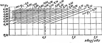
Table 1 shows the capacitances of the capacitors for excitation of asynchronous generators (U=380 V, 750...1500 rpm). Here reactive power Q is determined by the formula:
Q = 0.314 U2 C 10-6,
where C is the capacitance of the capacitors, μF.
| Generator power, kVA | Idling | Full load | ||||
| capacity, µF | reactive power, kvar | cos = 1 | cos = 0.8 | |||
| capacity, µF | reactive power, kvar | capacity, µF | reactive power, kvar | |||
| 2,0 3,5 5,0 7,0 10,0 15,0 | 28 45 60 74 92 120 | 1,27 2,04 2,72 3,36 4,18 5,44 | 36 56 75 98 130 172 | 1,63 2,54 3,40 4,44 5,90 7,80 | 60 100 138 182 245 342 | 2,72 4,53 6,25 8,25 11,1 15,5 |
Table 1
As can be seen from the above data, the inductive load on the asynchronous generator, which reduces the power factor, causes a sharp increase in the required capacity. To maintain a constant voltage with increasing load, it is necessary to increase the capacitor capacity, that is, connect additional capacitors. This circumstance must be considered as a disadvantage of the asynchronous generator.
The rotation frequency of an asynchronous generator in normal mode must exceed the asynchronous one by a slip value S = 2...10%, and correspond to the synchronous frequency. Failure to comply with this condition will lead to the fact that the frequency of the generated voltage may differ from the industrial frequency of 50 Hz, which will lead to unstable operation of frequency-dependent consumers of electricity: electric pumps, washing machines, devices with a transformer input.
A decrease in the generated frequency is especially dangerous, since in this case the inductive resistance of the windings of electric motors and transformers decreases, which can cause their increased heating and premature failure.
An ordinary asynchronous squirrel-cage electric motor of appropriate power can be used as an asynchronous generator without any modifications. The power of the electric motor-generator is determined by the power of the connected devices. The most energy-intensive of them are:
- household welding transformers;
- electric saws, electric jointers, grain crushers (power 0.3...3 kW);
- electric furnaces of the “Rossiyanka” and “Dream” types with a power of up to 2 kW;
- electric irons (power 850…1000 W).
I would especially like to dwell on the operation of household welding transformers. Their connection to an autonomous source of electricity is most desirable, because when operating from an industrial network, they create a number of inconveniences for other electricity consumers.
If a household welding transformer is designed to work with electrodes with a diameter of 2...3 mm, then its total power is approximately 4...6 kW, the power of the asynchronous generator to power it should be within 5...7 kW. If a household welding transformer can work with electrodes with a diameter of 4 mm, then in the heaviest mode - “cutting” metal, the total power consumed by it can reach 10...12 kW, respectively, the power of an asynchronous generator should be within 11...13 kW.
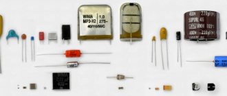
As a three-phase bank of capacitors, it is good to use so-called reactive power compensators, designed to improve cosφ in industrial lighting networks. Their typical designation: KM1-0.22-4.5-3U3 or KM2-0.22-9-3U3, which is deciphered as follows. KM - cosine capacitors impregnated with mineral oil, the first number is the size (1 or 2), then the voltage (0.22 kV), power (4.5 or 9 kvar), then the number 3 or 2 means three-phase or single-phase version, U3 (temperate climate of the third category).
In the case of self-manufacturing of the battery, you should use capacitors such as MBGO, MBGP, MBGT, K-42-4, etc. for an operating voltage of at least 600 V. Electrolytic capacitors cannot be used.
The option discussed above for connecting a three-phase electric motor as a generator can be considered classic, but not the only one. There are other methods that have proven themselves just as well in practice. For example, when a bank of capacitors is connected to one or two windings of an electric motor generator.