Almost every enterprise that consumes electricity is faced with the need to use capacitor units (CCRM) to compensate for reactive power.
How to correctly calculate the power of a capacitor unit? On the Internet you can find many sites describing calculation methods, but often these calculations lead to absurd results.
Here we will look at two approaches to calculating the power of a capacitor installation and try to understand which one is most suitable in a given case. When making calculations, we will, in practical terms, focus on 0.4 kV UKRM, although similar calculations can be carried out for capacitor installations of 6-10 kV.
Calculation of the required power factor using nomograms
The vast majority of methods for calculating the power of capacitor units described on the Internet are based on this approach (see the book by V.P. Ilyashov. Automatic power control of capacitor units. 1977).
To determine the power of a capacitor unit, the following formula is used
Q = P * K
where Q is the reactive power of the capacitor unit; P is the active power of the compensated consumer; K is the coefficient calculated from the ratio of the natural and required power factor (cos φ).
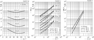
The K coefficient is calculated using a nomogram (see figure) or a similar table.
The nomogram shows, based on the values of the natural and required power factor (cos φ), the required specific reactive power of the capacitor unit per unit of active power consumed.
For example, if the natural cos φ = 0.7, and the specified value of cos φ = 0.93 and the active load is 2500 kVA, then from the nomogram curves we find the specific value of the required power of the capacitor unit equal to 0.62 kVAr/kW; hence the required power of the capacitor unit is 0.62-2500 = 1550 kVAr . Let's remember this value.
Calculator for calculating the capacitance of working and starting capacitors
When connecting an asynchronous electric motor to a single-phase 220/230 V network, it is necessary to ensure a phase shift on the stator windings in order to simulate a rotating magnetic field (RPF), which causes the motor rotor shaft to rotate when it is connected to the “native” three-phase AC networks. Known to many who are familiar with electrical engineering, the ability of a capacitor to give electric current a “head start” by π/2 = 90° compared to voltage provides a good service, since this creates the necessary torque that forces the rotor to rotate in already “non-native” networks.
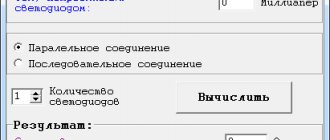
Calculator for calculating working and starting capacitors
But the capacitor must be selected for these purposes, and it must be done with high precision. That is why readers of our portal are provided with an absolutely free use of a calculator for calculating the capacity of the working and starting capacitor. After the calculator, the necessary explanations will be given on all its points.
Calculator for calculating the capacitance of working and starting capacitors
Go to calculations
The following dependencies were used for the calculation:
| Winding connection method and connection diagram for working and starting capacitors | Formula |
| Star connection | Working capacitor capacity – Av |
| Cр=2800*I/U; I=P/(√3*U*η*cosϕ); Cр=2800*P/(/(√3*U²*η*cosϕ). | |
| Triangle connection | Working capacitor capacity - Cp |
| Cр=4800*P/(/(√3*U²*η*cosϕ). | |
| Starting capacitor capacity for any connection method Cп=2.5*Cр | |
| Explanation of symbols in formulas: Cр – capacity of the working capacitor in microfarads (μF); Cp – starting capacitor capacity in microfarads; I – current in amperes (A); U – network voltage in volts (V); η – engine efficiency, expressed as a percentage divided by 100; cosϕ – power factor. | |
The data obtained from the calculator can be used to select capacitors, but they are unlikely to be found with exactly the same ratings as will be calculated. Only in rare exceptions can there be coincidences. The selection rules are:
- If there is an “exact hit” in the capacitance rating that exists for the desired series of capacitors, then you can choose just that one.
- If there is no “hit”, then choose a container that is lower in a number of ratings. The above is not recommended, especially for work capacitors, as this can lead to an unnecessary increase in operating currents and overheating of the windings, which can lead to an inter-turn short circuit.
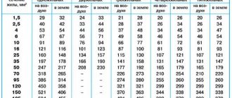
- In terms of voltage, capacitors are selected with a nominal value of at least 1.5 times greater than the network voltage, since at the time of start-up the voltage at the capacitor terminals is always increased. For a single-phase voltage of 220 V, the operating voltage of the capacitor must be at least 360 V, but experienced electricians always advise using 400 or 450 V, since the reserve, as you know, “does not last a pocket.”
Here is a table with the ratings of operating and starting capacitors. The capacitors of the CBB60 and CBB65 series are given as an example. These are polypropylene film capacitors, which are most often used in connection circuits for asynchronous motors. The CBB65 series differs from the CBB60 in that they are housed in a metal case.
Electrolytic non-polar capacitors CD60 are used as starting capacitors. They are not recommended for use as workers, since their long operating time makes their life shorter. In principle, both CBB60 and CBB65 are suitable for starting, but they have larger dimensions than CD60 with equal capacities. The table provides examples of only those capacitors that are recommended for use in electric motor connection circuits.
| Polypropylene film capacitors CBB60 (Russian analogue of K78-17) and CBB65 | Electrolytic non-polar capacitors CD60 | |
| Image | ||
| Rated operating voltage, V | 400; 450; 630 V | 220—275; 300; 450 V |
| Capacity, uF | 1.5; 2.0;2.5; 3.0; 3.5; 4.0; 5.0; 6.0; 7.0; 8.0; 10; 12; 14; 15; 16; 20; 25; thirty; 35; 40; 45; 50; 60; 65; 70; 75; 80; 85; 90; 100; 120; 150 µF | 5.0; 10; 15; 20; 25; 50; 75; 100; 150; 200; 250; 300; 350; 400; 450; 500; 600; 700; 800; 1000; 1200; 1500 uF |
In order to “gain” the required capacitance, you can use two or more capacitors, but with different connections, the resulting capacitance will be different. When connected in parallel, it will add up, and when connected in series, the capacitance will be less than any of the capacitors. Nevertheless, such a connection is sometimes used in order to connect two capacitors with a lower operating voltage to obtain a capacitor whose operating voltage will be the sum of the two connected. For example, by connecting two 150 µF and 250 V capacitors in series, we get a resulting capacitance of 75 µF and an operating voltage of 500 V.
Series and parallel connection of capacitors
In order to calculate the capacitance of two capacitors connected in series, readers are provided with a simple calculator where you simply select two capacitors from a range of existing values.
Calculator for calculating the resulting capacitance of two capacitors connected in series
Go to calculations
Is it possible to connect a three-phase asynchronous motor to a 220 V network yourself?
Typically, this operation is trusted only to electricians with practical experience. However, you can connect the engine yourself. This is proven by the article on our portal: “How to connect a three-phase motor to a 220 V network.”
Calculation based on power balance
In some cases, for example, if a capacitor unit is installed at a transformer substation, when determining its power it is necessary to take into account the characteristics of the supplying power system, that is, the transformer.
The “Guidelines for reactive power compensation in distribution networks” adopted in the USSR in 1974 established the initial data for determining the power of compensating devices, which are determined by the maximum values of reactive power and can be transferred to the consumer from the power system in the modes of the highest and lowest reactive loads (B. Y. Lipkin, Power supply of industrial enterprises and installations, 1981).
Power Q of the compensating device is defined as the difference between the actual maximum reactive power Q1 of the consumer load and the maximum reactive power Q2 provided to the enterprise by the power system under the conditions of its operating mode:
Q = Q1 - Q2 = P (tg φ1 - tan φ2)
where P is the power of the active load of the consumer, tg φ1 is the actual (natural) tangent of the angle corresponding to the power factor cos φ1, and tg φ2 is the optimal (required) tangent of the angle corresponding to the power factor established for the consumer by the conditions of the supplying power system (transformer).
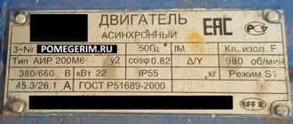
In the example discussed above, the active power of the transformer is 2500 kVA, and its reactive power (according to the passport data) is 1900 kVA. As a result, since part of the reactive power is supplied by the transformer, only the reactive power difference of 650 kVA , which is more than half the value obtained by the first method.
Pros and cons of having a reactive component
When powering a load that is only active in nature, the phase shift between current and voltage is zero. This case can be called ideal; in this case, the supply networks can be used completely, since there are no losses due to the useless reactive component.
The reactive component is not so useless. It forms the electromagnetic field necessary for adequate operation of the reactive load.
In real life, the load, as a rule, is inductive in nature (the current lags behind the voltage), and is active-reactive. Therefore, whenever they talk about phase shift and cosine, they mean an inductive load.
Let me clarify: we are talking about the industrial sector, where this problem is especially acute. In everyday life, the load is usually capacitive in nature. But given the scanty power and high cos φ, reactive power is not used in everyday life.
The main sources of the reactive component of electricity are transformers and asynchronous electric motors.
Purely reactive load occurs only in the textbook. In reality, due to losses, there is always an active component too.
The reactive component of the supply power is a negative factor because:
- Additional losses occur in power transmission lines,
- The capacity of power lines is reduced,
- There is a voltage drop on transmission lines due to an increase in the reactive component of the supply network current,
- There is additional heating and wear of electricity distribution and transformation systems,
- Resonance effects may occur at harmonic frequencies, which can cause overheating of the supply networks.
For the above reasons, it is necessary to reduce the share of reactive power in the network (increase the cosine) - this is beneficial for both energy supply organizations and consumers with distributed networks.
Example: To transmit a certain power, a current of 100 A is required at cos φ = 1. However, at cos φ = 0.6, to provide the same power, a current of 166 A will need to be transmitted! Accordingly, you need to think about increasing the power of the supply network and increasing the cross-section of the wires...
That's why:
Reactive power is a portion of the power of a power source, this power was stored in a magnetic field and then returned back to the source.
Comparison of calculations and conclusions
The required power of the condenser unit calculated using the first method looks overestimated. The cost of a capacitor installation for the active power value of 2500 kVA considered in the example will be more than 750 thousand rubles, which corresponds to almost 20% of the cost of the entire substation.
The reason for the overestimation of the result is that this calculation method does not take into account the characteristics of the supplying power system, assuming only active power in its composition. In fact, as the second calculation method shows, the supply energy system can have much greater power and include not only an active but also a reactive component. Taking this circumstance into account makes it possible to significantly reduce the power requirements of the capacitor installation and save significant funds .
Calculation of the capacitor bank and selection of elements of the compensating device
The capacitor bank must have a rated reactive power Q
KU and withstand the specified voltage. The battery is made up of standard capacitor banks connected in parallel in rows, and the rows are connected in series. Basic data of typical capacitors are given in table. 1.
Table 1
| Type of capacitor | Nominal value | ||
| Voltage, U B, kV | Power, Q B, kvar | Capacity, C B, µF | Current frequency, Hz |
| KM2–6.3–24–U1 | 6,3 | 1,93 | |
| KM2–10.5–21–2U1 | 10,5 | 0,69 | |
| KSK–6.3–75U1 | 6,3 | 6,02 | |
| KSK–6.3–150U1 | 6,3 | 12,04 | |
| KSK–10.5–75U1 | 10,5 | 2,17 | |
| KSK–10.5–150U1 | 10,5 | 4,33 |
The total number of cans in the battery must be at least
where Q
B – reactive power of one bank.
The number of consecutively included rows is determined by the formula
where U
w – voltage on substation buses;
U
B – rated voltage of the capacitor bank;
TO
T – coefficient taking into account the temperature of the condenser,
K
t=1.1;
TO
P=1.4 – coefficient taking into account the increase in voltage that appears when installing a reactor tuned to the third harmonic.
Number of cans in one row.
The capacitance of the capacitor bank is equal to
where C
B – capacity of one can (see Table 1).
If the capacity of the jar is not specified, it can be determined from the relation
The reactor is selected according to the third harmonic resonance conditions.
X
L3 =
X
KUS3, 3
ωL
KU = 1/ 3
ωC
KU,
L
KU =1/9
ω
2
C
KU
The reactor current is equal to the capacitor bank current
I
=
U
KU /
X
KUS =
U
KU ×
ω
×
C
KU
For HRSG with a rated voltage of 25 kV, the reactor is manufactured with a core made of electrical steel FROM-3200/35U1 (single-phase reactor with natural oil cooling). Typical reactor power 3200 kvar, voltage class 35 kV, open installation.
The reactor has the following technical parameters:
The effective value of the rated current is 230 A.
Copper losses at a current of 230 A 10 kW.
Power loss in steel is 10.5 kW.
Total weight 9000 kg.
Oil weight 2350 kg.
The harmonic components of the current through the reactor should not exceed: 160 A at a frequency of 50 Hz and 30 A at a frequency of 250 Hz.
The reactor has a winding tap switching device without excitation. The reactor inductance at various switch positions is as follows:
| Switch position | |||||
| Inductance, mH | |||||
| Inductive reactance, Ohm | 33,6 | 31,2 | 28,6 | 26,1 | 23,6 |
| Active resistance, Ohm | 0,147 | 0,141 | 0,135 | 0,128 | 0,122 |
The current transformer is also selected based on the current value of the capacitor bank. The main parameters of current transformers are given in table. 2.
table 2
| Type | Rated voltage, kV | Rated current, A | Multiplicity of electro-dynamic resistance to d |
| Primary | Secondary | ||
| TFND-35M | 15–600; 800; 1000 |
The selected current transformer is checked for short-circuit shock current:
I
y=2.55
I
short circuit
,
where U
n – rated voltage on the substation buses, equal to 27.5 kV;
X
c – resistance up to the short-circuit point.
X
c =
x
l +
x
tr,
where x
l – line resistance to the traction substation;
X
tr – resistance of the traction substation transformer.
X
l=
x
0
l
,
where x
0 – resistivity of 1 km line, Ohm/km;
x
0=0.4 Ohm/km;
l
– length of the intersubstation zone (see task).
,
where S
n.tr. – rated power of the transformer, MV×A; in this work, a transformer with a power of 40 MV×A is adopted;
u
k – short-circuit voltage
step-down transformer between the primary and traction windings, %; for the adopted transformer u
k = 10.5%.