What is a diode
A semiconductor diode or simply a diode is a radio element that allows electric current to pass in only one direction and blocks its passage in the other direction. In a hydraulic analogy, a diode can be compared to a check valve: a device that allows fluid to flow in only one direction.
check valve
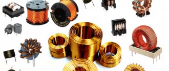
A diode is a radio element with two terminals. Some diodes look almost the same as resistors:
And some look a little different:
There are also SMD versions of diodes:
The terminals of the diode are called anode and cathode . Some people mistakenly call them “plus” and “minus”. This is not true. You can't say that.
In the diagrams the diode is designated as follows
It can only pass electric current from the anode to the cathode.
Possible faults
During operation of devices with diodes, various breakdowns can occur. This occurs due to aging of the elements or their depreciation.
Repair specialists distinguish 4 types of faults.
Among them are:
- Electrical breakdown. This is one of the most common failures that occur with diodes. It is reversible, since it does not lead to destruction of the diode crystal. This can be corrected by gradually reducing the supplied voltage.
- Thermal breakdown. Such a malfunction is more destructive for the diode. It occurs due to poor heat dissipation or overheating in the pn junction region. The latter is formed only if the device is powered by a current with excessively high rates. Without repairs, the problem will only get worse. In this case, the vibrations of the atoms of the diode crystal will increase, which will lead to its deformation and destruction.
- Break. When this malfunction occurs, the device stops flowing electrical current in both directions. Thus, it becomes an isolator blocking the entire system. To eliminate a breakdown, you need to accurately determine its location. To do this, special highly sensitive testers should be used, which will increase the chance of detecting a break.
- A leak. This breakdown is understood as a violation of the integrity of the housing caused by physical or other impact on the device.
The diode is an important design element that ensures proper and uninterrupted operation of the device. By choosing this element correctly and ensuring optimal operating conditions, you can avoid any malfunctions.
What does a diode consist of?
In our world there are substances that perfectly conduct electric current. This mainly includes metals, for example, silver, copper, aluminum, gold and so on. Such substances are called conductors. There are substances that conduct electricity very poorly - porcelain, plastics, glass, and so on. They are called dielectrics or insulators. Between conductors and dielectrics are semiconductors . These are mainly germanium and silicon.
Once germanium or silicon is mixed with a minute fraction of arsenic or indium, an N-type semiconductor is formed when mixed with arsenic; or a P-type semiconductor when mixed with indium.
Now if these two P and N type semiconductors are welded together, a PN junction is formed at their junction. This is the structure of a diode. That is, the diode consists of a PN junction.
diode structure
The P-type semiconductor in the diode is the anode, and the N-type semiconductor is the cathode.
Let's open the Soviet D226 diode and see what's inside it by grinding off part of the body on an emery wheel.
diode D226
This is the same PN junction
PN junction diode
Reading an Electrical Diagram
The diagram itself, on which the symbols are drawn, is called a schematic diagram. It not only shows how certain elements of the circuit are connected, but also explains how the entire device works, showing the principle of its operation. To achieve this result, it is important to correctly show the individual groups of elements and the connection between them.
In addition to the fundamental one, there are also installation ones. They are designed to accurately display each element in relation to each other. The arsenal of radioelements is huge. New ones are constantly being added. Nevertheless, the UGO in all diagrams is almost the same, but the letter code is significantly different. There are 2 types of standard:
- state, this standard may include several states;
- international, used almost all over the world.
But whatever standard is used, it must clearly show the designation of radio components on the diagram and their name. Depending on the functionality, UGO radio components can be simple or complex. For example, several conditional groups can be distinguished:
- power supplies;
- indicators, sensors;
- switches;
- semiconductor elements.
This list is incomplete and serves for illustrative purposes only. To make it easier to understand the symbols of radio components in the diagram, you need to know the principle of operation of these elements.
How to determine the anode and cathode of a diode
1) on some diodes the cathode is marked with a stripe that differs from the color of the body
2) you can check the diode with a multimeter and find out where its cathode is and where its anode is. At the same time, check its performance. This method is ironclad ;-). How to check a diode using a multimeter can be found in this article.
It is very easy to remember where the anode is and where the cathode is, if you remember the funnel for pouring liquids into the narrow necks of bottles. The funnel is very similar to the diode circuit. We pour it into the funnel, and the liquid flows very well, but if you turn it upside down, try pouring it through the narrow neck of the funnel ;-).
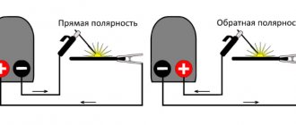
Methods for determining polarity
There are several ways to find the cathode and anode on a diode. Moreover, each of them differs in the degree of reliability. Among the methods that involve the use of devices, the following are distinguished:
- Measured with a multimeter.
- Supply a limited voltage to the resistor (connecting an independent power source).
- By connecting an oscilloscope.
Such methods have proven themselves well on diodes with low and medium power and a normal glow pattern. Other simple and popular methods include:
- Study the attached technical documents.
- Representation of polarity in a schematic diagram.
Important! We remind you about possible erroneous labeling or inappropriate information in the documentation. This happens quite often.
Diode in DC circuit
As we have already said, a diode allows electric current to pass in only one direction. To show this, let's put together a simple diagram.
direct connection of the diode
Since our incandescent lamp is 12 Volt, therefore, we also set the value on the power supply to 12 V and assemble the entire electrical circuit according to the diagram above. As a result, our light bulb burns perfectly. This indicates that electric current is passing through the diode. In this case, the diode is said to be connected in the forward direction.
direct diode
Let's now change the leads of the diode. As a result, the diagram will take this form.
reverse diode switching
As you can see, the light bulb does not light up, since the diode does not allow electric current to pass through, that is, it blocks its passage, although the power source produces its honest 12 Volts.
reverse diode switching
What conclusion can be drawn from this? A diode conducts direct current in only one direction.
Where to start reading diagrams?
In order to learn how to read circuits, first of all, we must study what a particular radio element looks like in a circuit. In principle, there is nothing complicated about this. The whole point is that if the Russian alphabet has 33 letters, then in order to learn the symbols of radio elements, you will have to try hard.
Until now, the whole world cannot agree on how to designate this or that radio element or device. Therefore, keep this in mind when you collect bourgeois schemes. In our article we will consider our Russian GOST version of the designation of radioelements
Diode in AC circuit
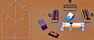
For those who have forgotten what alternating current is, read this article. So, in order to consider the operation of a diode in an alternating current circuit, let's draw a diagram. Here we see a frequency generator G, a diode and two terminal blocks X1 and X2, from which we will take a signal using an oscilloscope.
My frequency generator looks like this.
frequency generator
We will take an oscillogram using a digital oscilloscope
The generator produces alternating sinusoidal voltage.
sine wave
What happens after the diode? We connect to terminals X1 and X2 and see this oscillogram.
AC voltage after diode
The diode cut out the bottom part of the sine wave, leaving only the top part.
What happens if we change the diode leads? The scheme will look like this.
alternating current after diode
What do we get at terminals X1 and X2? Let's look at the oscillogram.
alternating current after diode
Wow! The diode cut off only the positive part of the sine wave!
Foreign marking of microcircuits (using the Pro Electron system)
In Europe and the West, there are several established labeling schemes for electronic components, each of which has minor differences in its field of application. But the basic principles remain common to all, and they are all listed in the classification adopted by the international Pro Electron association.
According to the Pro Electron classification, the marking of microcircuits consists of three alphabetic symbols followed by a numerical value.
The first letter indicates the method of signal conversion in the circuit:
T – analog conversion; S – digital conversion; U – mixed type transformation.
The second letter after the type of signal conversion does not have any fixed meaning (it is selected by the manufacturer). The exception is the letter “H”, which always denotes the hybrid operating principle of the chip.
In the case of digital electronic components, the first two letters indicate the features of the device:
FY – ESL line; GA – low-current TTL chips; GF – standard TTL; GJ – productive TTL; H – complementary microcircuits.
The third symbol in the microcircuit marking indicates the range of its operating temperatures:
A) not nominated; B) from 0 to +70 °C; C) from -55 to +125 °C; D) from -25 to +70 °C; E) from -25 to +85 °C; F) from -40 to +85 °C; G) from -55 to + 85 °C.
After the letter indicating the temperature range, there is a four-digit number - this is the serial number of the chip.
Following the serial number, the type of case is indicated in the microcircuit marking. This designation can be two-letter or one-letter.
The meaning of the first letter in two-letter markings:
C – cylindrical body; D – DIP housing (contacts are located in two rows along the edges of the microcircuit); E – DIP housing with heat dissipator; F – quadrangular flat (double-sided placement of contacts); G – quadrangular flat (four-sided placement of contacts); K – TO-3 body; M – multi-row body; Q – symmetrical arrangement of contacts along four edges; R – housing with a four-row arrangement of contacts and an external heat dissipator; S – contacts are placed in one row; T – housing with three-row arrangement of contacts.
We recommend reading: MC34063 datasheet in Russian
The meaning of the second letter in two-letter markings:
G – glass ceramics; M – metal; P – plastic; X – other materials.
If the serial number in the microcircuit marking is followed by one letter, it should be interpreted as follows:
C – cylindrical body; D – ceramic body; F – flat body; P – DIP plastic housing; Q – four-row arrangement of contacts; T – miniature plastic case; U – unpackaged integrated circuit.
The next two digits after the housing type are the serial number of the electronic component. The last number in the microcircuit marking is its operating temperature range. It should be interpreted as follows:
0) not nominated; 1) from 0 to +70 °C; 2) from -55 to +125 °C; 3) from -10 to +85 °C; 4) from +15 to +55 °C; 5) from -25 to +70 °C; 6) from -40 to + 85 °C.
We hope this information will help you understand the variety of markings, and you can easily select and buy microcircuits with the desired characteristics.
Diode Characteristics
Let's look at the characteristics of the KD411AM diode. We look for its characteristics on the Internet, typing into the search “datasheet KD411AM”
To explain the parameters of the diode, we also need its current-voltage characteristic
1) Reverse maximum voltage Urev is the voltage of the diode that it can withstand when connected in the reverse direction, while current Irev will flow through it - the current strength when the diode is connected in reverse. When the reverse voltage in the diode is exceeded, a so-called avalanche breakdown occurs, as a result of which the current sharply increases, which can lead to complete thermal destruction of the diode. In our diode under study, this voltage is 700 Volts.
2) Maximum forward current Ipr is the maximum current that can flow through the diode in the forward direction. In our case it is 2 Amperes.
3) Maximum frequency Fd , which must not be exceeded. In our case, the maximum diode frequency will be 30 kHz. If the frequency is higher, our diode will not work correctly.
Application area
The scope of use of these parts in modern radio engineering is high. It is difficult to find a device that works without these parts. To understand why a diode is needed, here are a few examples:
- Diode bridges - contain from 4 to 12 semiconductor devices that are connected to each other. The main task of diode bridges is to rectify current, and they are actively used, for example, in creating generators for cars.
- Detectors - created by combining diodes and capacitors. As a result, it becomes possible to isolate low-frequency modulation from various signals. Used in the manufacture of radio and television receivers.
- Protective devices - allow you to protect the electrical circuit from possible overloads. Several products are connected in the opposite direction. When the circuit is working normally, they remain in the closed position. As soon as the input voltage reaches critical levels, the device is activated.
- Switches - such systems based on these products allow switching high-frequency signals.
- Spark protection systems - the creation of a shunt-diode barrier allows you to limit the voltage in the electrical circuit. To increase the degree of protection, special current-limiting resistors are used together with semiconductor parts.
These are just a few examples of the use of diodes. They are quite reliable devices that can be used to solve a large number of problems. Most often, these radio components fail due to natural aging or overheating.
If an electrical breakdown of a product occurs, its consequences are rarely irreversible, since the crystal is not destroyed.
Types of diodes
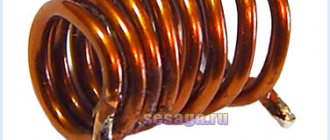
Zener diodes
Zener diodes are the same diodes. Even from the name it is clear that zener diodes stabilize something. And they stabilize the tension . But for the zener diode to perform stabilization, one condition is required. They should be connected oppositely than the diodes. The anode is negative and the cathode is positive. Strange isn't it? But why is that? Let's figure it out. In the Volt-Amp characteristic (CVC) of a diode, the positive branch is used - the forward direction, but in a zener diode, the other part of the CVC branch is the reverse direction.
Below in the graph we see a 5 Volt zener diode. No matter how much the current strength changes, we will still receive 5 Volts ;-). Cool, isn't it? But there are also pitfalls. The current strength should not be greater than in the description for the diode, otherwise it will fail due to high temperature - Joule-Lenz Law. The main parameter of the zener diode is the stabilization voltage (Ust). Measured in Volts. On the graph you see a zener diode with a stabilization voltage of 5 Volts. There is also a current range at which the zener diode will operate - this is the minimum and maximum current (Imin, Imax) . Measured in Amperes.
Zener diodes look exactly the same as conventional diodes:
On the diagrams they are indicated like this:
LEDs
LEDs are a special class of diodes that emit visible and invisible light. Invisible light is light in the infrared or ultraviolet range. But for industry, LEDs with visible light still play a big role. They are used for display, design of signs, illuminated banners, buildings and also for lighting. LEDs have the same parameters as any other diode, but usually their maximum current is much lower.
The maximum reverse voltage (Urev) can reach 10 Volts. The maximum current (Imax) will be limited for simple LEDs to about 50 mA. More for lighting. Therefore, when connecting a conventional diode, you need to connect a resistor in series with it. The resistor can be calculated using a simple formula, but ideally it is better to use a variable resistor, select the desired glow, measure the value of the variable resistor and put a constant resistor with the same value there.
LED lighting lamps consume pennies of electricity and are cheap.
LED strips consisting of many SMD LEDs are in great demand. They look very nice.
In the diagrams, LEDs are designated as follows:
Do not forget that LEDs are divided into indicator and lighting. Indicator LEDs have a weak glow and are used to indicate any processes occurring in an electronic circuit. They are characterized by a weak glow and low current consumption
Well, lighting LEDs are those that are used in your Chinese lanterns, as well as in LED lamps
The LED is a current device, that is, for its normal operation it requires a rated current, not a voltage. At rated current, a certain voltage drops across the LED, which depends on the type of LED (rated power, color, temperature). Below is a plate showing what voltage drop occurs on LEDs of different colors at rated current:
You can learn how to check the LED in this article.
Thyristors
Thyristors are diodes whose conductivity is controlled using the third terminal - the control electrode (CE). The main use of thyristors is to control a powerful load using a weak signal supplied to the control electrode. Thyristors look similar to diodes or transistors. Thyristors have so many parameters that there is not enough article to describe them. The main parameter is Ios, avg. - the average value of the current that should flow through the thyristor in the forward direction without harm to its health. An important parameter is the opening voltage of the thyristor - (Uу), which is supplied to the control electrode and at which the thyristor opens completely.
and this is what power thyristors look like, that is, thyristors that operate with high current:
In the diagrams, triode thyristors look like this:
There are also types of thyristors - dinistors and triacs. Dinistors do not have a control electrode and it looks like a regular diode. Dinistors begin to pass electric current through themselves in direct connection when the voltage across it exceeds a certain value. Triacs are the same as triode thyristors, but when turned on, they pass electric current through them in two directions, so they are used in circuits with alternating current.
Types of Electronic Circuits
In radio electronics, there are several types of circuits: circuit diagrams, wiring diagrams, block diagrams, voltage and resistance maps.
Schematic diagrams
Such an electrical diagram gives a complete picture of all the functional components of the circuit, the types of connections between them, and the operating principle of electrical equipment. Circuit diagrams are commonly used in distribution networks. They are divided into two types:
- Single-line. This drawing shows only power circuits.
- Full. If the electrical installation is simple, then all its elements can be displayed on one sheet. To describe equipment that contains several circuits (power, measuring, control), drawings are made for each unit and placed on different sheets.
Block diagrams
In radio electronics, a block is an independent part of an electronic device. A block is a general concept; it can include both a small and a significant number of parts. A block diagram (or block diagram) gives only a general concept of the structure of an electronic device. It does not display: the exact composition of the blocks, the number of ranges of their functioning, the schemes according to which they are assembled. In a block diagram, blocks are represented by squares or circles, and the connections between them are represented by one or two lines.
The directions of signal passage are indicated by arrows. The names of the blocks in full or abbreviated form can be applied directly to the diagram. The second option is to number the blocks and decipher these numbers in a table located in the margins of the drawing. Graphic images of blocks can display the main parts or plot their operation.
Assembly
Wiring diagrams are convenient for creating an electrical circuit yourself. They indicate the location of each circuit element, communication methods, and the laying of connecting wires. The designation of radioelements on such diagrams usually approaches their natural appearance.
Voltage and resistance map
A voltage map (diagram) is a drawing in which, next to the individual parts and their terminals, the voltage values characteristic of the normal operation of the device are indicated. Voltages are placed in the gaps of the arrows, showing in which places measurements need to be made. The resistance map indicates the resistance values characteristic of a working device and circuits.
Other items
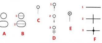
All radio components are connected to each other by conductors. In the diagram they are depicted as straight lines and drawn strictly horizontally and vertically. If the conductors have an electrical connection when crossing each other, then a dot is placed at this place. In Soviet and American diagrams, to show that the conductors are not connected, a semicircle is placed at the intersection.
To designate variable capacitors, an arrow is used; it crosses out the capacitor diagonally. In trimmers, a T-shaped sign is used instead of an arrow. Varicond - a capacitor that changes capacitance depending on the applied voltage, is drawn like an alternating one, but the arrow is replaced by a short straight line, next to which there is the letter u. The capacitance is shown with a number and a microFarad (microFarad) is placed next to it. If the capacity is smaller, the letter code is omitted.
Another element that no electrical circuit can do without is a resistor. Indicated in the diagram as a rectangle. To show that the resistor is variable, an arrow is drawn on top. It can be connected either to one of the pins, or be a separate pin. For trimmers, a sign in the form of the letter t is used. As a rule, its resistance is indicated next to the resistor.
Symbols in the form of dashes can be used to indicate the power of fixed resistors. A power of 0.05 W is indicated by three oblique, 0.125 W - two oblique, 0.25 W - one oblique, 0.5 W - one longitudinal. High power is shown in Roman numerals. Due to the diversity, it is impossible to describe all the designations of electronic components on the diagram. To identify a particular radio element, use reference books.
Forward and reverse voltage
The voltage that affects the diode is divided according to two criteria:
- Direct voltage is the one at which the diode opens and direct current begins to flow through it, while the resistance of the device is extremely low.
- Reverse voltage is one that has reverse polarity and ensures that the diode closes with reverse current passing through it. At the same time, the resistance indicators of the device begin to increase sharply and significantly.
This leads to an increase in the parameters of the forward current passing through the diode. When this device is closed, virtually the entire voltage is applied to it, for this reason the reverse current passing through the diode is insignificant, and the transition resistance reaches peak parameters.
How to learn to read circuit diagrams
There are really only a few ways. This is theory and practice. If you learn the designation of radio components, this does not mean that you have learned circuit design. It's like learning your ABC's, but without grammar and practice you won't learn the language.
Theory is circuit design, books, a description of the principle of operation of the circuit. Practice involves assembling devices, repairing and soldering.
For example, a simple amplifier circuit with one transistor.
Input X1 plus (left or right channel), X2 minus. The sound signal is sent to electrolytic capacitor C1. It protects transistor VT1 from short circuiting, since transistor VT1 is constantly open using a voltage divider across R1 and R2. The voltage divider sets the operating point at the base of transistor VT1, and the transistor does not distort the input signal. Resistor R3 and capacitor C2, which are connected to the emitter of transistor VT1, perform the function of thermal stabilization of the operating point as the temperature of the transistor increases. Electrolytic capacitor C3 accumulates and filters the supply voltage. The BF1 dynamic head serves as an audio signal output.
Is it possible to understand this only by learning the designations of radio components without circuit design and theory? Unlikely.
The situation is even more complicated with digital technology.
What kind of microcontroller is this, what functions does it perform, what firmware and what fuses are installed in it? And the second microcircuit, what amplifier is it? Without datasheets and a description of the circuit, it will not be possible to understand its operation.
Study circuit design, theory and practice. Simply learning the names of the parts will not help you understand the circuitry. The designation of radio components can be learned on its own with practice and accumulation of knowledge. It all depends on the chosen industry. Signalmen have one circuit design, mobile equipment repairmen have another. And those who deal with sound will not really understand electricians. As well as vice versa. To understand another industry, its circuitry and operating principles, you need to immerse yourself in it.
Circuit diagrams are a kind of language that has different dialects.
Therefore, one should not create illusions. Study circuit design and assemble circuits.
Recommended reading: Debug board
Schematic diagrams help to assemble devices, and when studying the theory, to understand the operation of the device. Without knowledge and experience, a diagram is just a diagram.